How to Make Arduino Development Board with 5v 3A Power Supply
Last Updated on August 16, 2024 by Engr. Shahzada Fahad
Table of Contents
Arduino Development Board:
How to Make Arduino Development Board with 5v 3A Power Supply- In today’s article, you will learn how to make an Arduino Development Board at home. This Arduino development board has a 5V and 3A power supply, an I2C-supported OLED display module, 5V SPDT-type relays, a LoRa transceiver module for long-range wireless communication, and a 5V buzzer.
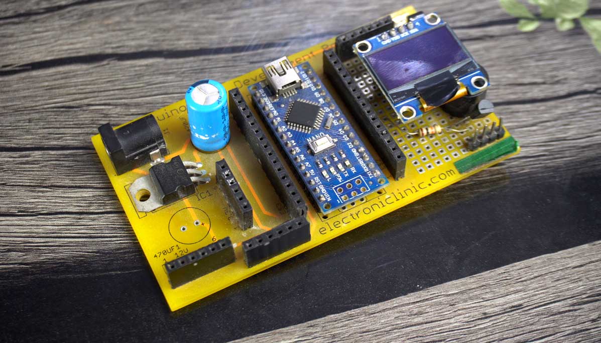
You may have seen this development board being used in most of my videos. It is good for basic prototyping, and I have made several projects using this development board. But there comes a time when you feel the need to advance a little.
The basic objective behind using a development board is to save time and money. A development board should have enough power so that you can easily test different projects with it.
I replaced this development board because it is based on the 7805 voltage regulator, and as you know, it can handle a maximum current of 1A if a good heatsink is used. So if you use a 7805 voltage regulator, you can easily power up small sensors. But when it comes to servo motors, GSM modules, or HMI screens that require more current, the 7805 voltage regulator fails badly.
Then you have to use an external power supply. Some time ago, I made a 5V and 3A power supply that I have used with almost all controller boards. I used it to power up my portable monitor, motors, sensors, and even I have used it to charge my cell phone. When I was 100% satisfied with this 5V power supply, I thought why not update my development board.
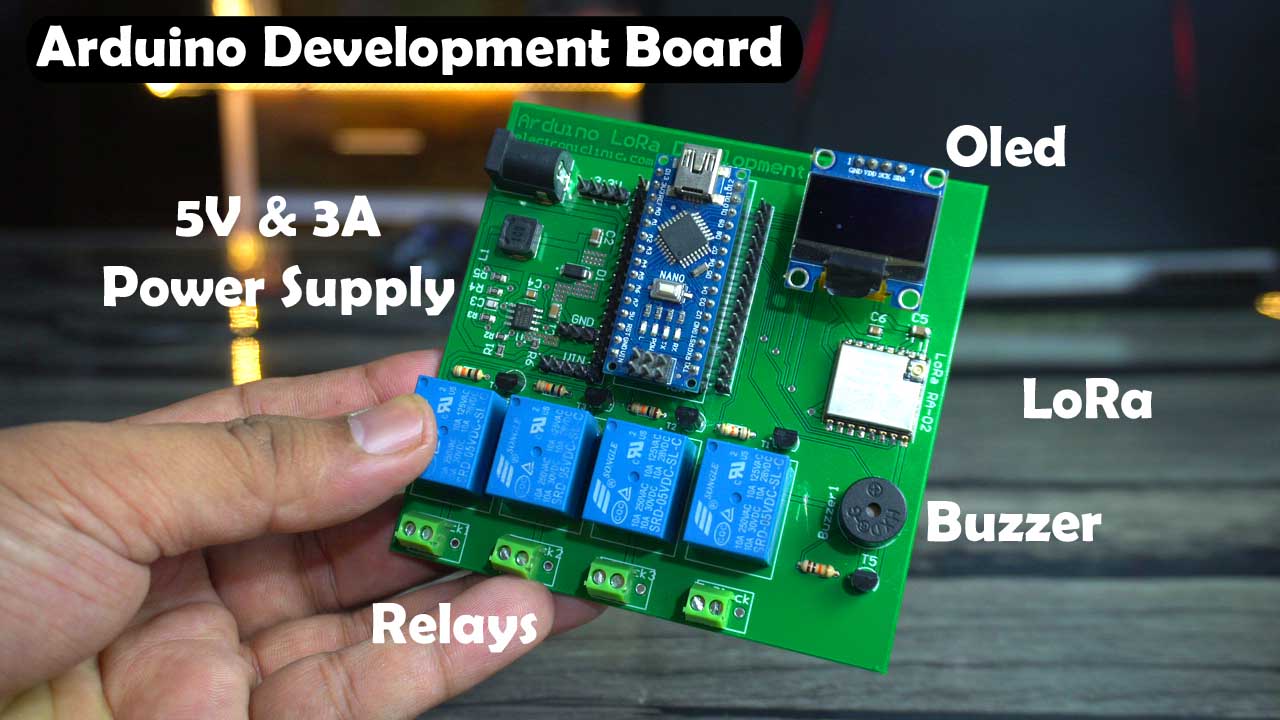
And as you can see, here is my updated development board based on the regulated 5V and 3A power supply. I have also used an OLED display module in this development board, which helps you monitor values of different sensors. The display I used here is the SSD1306 OLED display module. In this development board, I have also added 5V SPDT type relays, which allow you to control high voltage AC and DC loads. And as you can see, there is also a buzzer on this board. Let’s say you are working on a project where you need to monitor different types of sensors. When the sensor value exceeds the threshold value, the buzzer turns on. Or if you want to create a security system and the sensor gets activated, the buzzer turns on.
In addition to that, I have also added a LoRa transceiver module in this development board because I am sure that after trying out basic Arduino projects, you will eventually need long-range wireless communication.

I have used the Ai-Thinker 433MHz Ra-02 LoRa module. I am really thankful to Ai-Thinker for sending me lots of these LoRa modules along with different antennas for testing the communication range.

And to connect other sensors and breakout boards, I have also added female headers. I have also added female headers for 3.3V, 5V, and GND connections. Let’s say you need to power up a servo or a GSM module, you can connect the 5V from the headers labeled as VIN.
I have given a full overview of the Arduino development board, and now let’s move on and take a look at its circuit diagram.
Amazon Links:
Arduino Nano USB-C Type (Recommended)
*Disclosure: These are affiliate links. As an Amazon Associate I earn from qualifying purchases.
About LoRa Ra-02:
Product Description:
Module Model: Ra-02
Package: SMD-16
Size: 17*16*(3.2 ±0.1)mm
Interface: SPI
Programmable bit rate: UP to 300Kbps
Frequency Range: 410-525 MHz
Antenna: IPEX
Max Transmit Power: 18±1 dBm
Power(Typical Values):
433MHz ( TX:93mA, RX:12.15mA, Standby:1.6mA)
470MHz (TX:97mA, RX:12.15mA, Standby:1.5mA)
Power Supply: 2.5 to 3.7V, Typical 3.3V
Operating Environment: -40 Co to 85Co
Storage Environment: -40 Co to 90Co , <90%RH
Weight: 0.45g
Arduino Development board Circuit Diagram:

I have used Altium designer for creating the Schematic and for designing the PCB. If you want to speed up and professionalize your PCB designing work, I recommend shifting to Altium Designer. I have added the trial link in the description below. One of the best things about Altium Designer is that you can share your designs with your team members using Altium 365. They can check your design, leave comments, and if there are any issues, they can fix them from anywhere in the world. Altium Designer also uses the world’s fastest components search engine, Octopart, so you won’t have any difficulty in searching for components. I have already explained in detail how to search for components and how to create a schematic and design a PCB using Altium Designer. You can watch my videos available on my YouTube channel “ Electronic Clinic”.

This is the LoRa Ra-02 433Mhz transceiver module and its NSS, SCK, MOSI, and MISO pins are connected to the Arduino pins 10, 13, 11, and 12. The reset pin of the LoRa module is connected to the Arduino pin 9.

And its 3.3V and GND pins are connected to the Arduino 3.3V and GND pins. And don’t forget to add these 22uF and 0.1uF decoupling capacitors.

A 5V buzzer is connected to the Arduino Pin D8 and I am using 2n2222 NPN transistor for controlling this buzzer. Connect the positive pin of the Buzzer to the 5V which is VIN and connect the GND pin of the Buzzer to the collector of 2N2222 NPN transistor. Connect emitter to the GND and connect the Base to the digital pin D8 through this 10K resistor.

4 relays are connected to the Arduino digital pins 4, 5, 6, and 7. Connections of all the relays are same. The type of relays I am using are SPDT and these are 5V relays. I am using the same transistor 2n2222. You might be thinking why am I using 2n2222 NPN transistor, so if you want to know why am I using this transistor and how to perform the calculations then you should read my article on different types of relays and how to use them. Anyway, there is a freewheeling diode connected across the coil pins used against back EMF protection. And this is a terminal block labeled as T Block for connecting AC or DC loads.

This is a 5V and 3A power supply based on the MP1584EN-LF-Z. I have already explained this in my previous article. In that article, I have also explained how to get different voltages at the output.

The GND and VCC pins of the SSD1306 Oled display module are connected to the Arduino GND and 3.3V, whereas the SCL and SDA pins of the Oled display module are connected to the Arduino A5 and A4 pins. A5 is the SCL and A4 is the SDA. And all the other headers are for connecting sensors, breakout boards, power supply wires. So, that’s all about the connections.
Arduino Development Board PCB Designing:
Anyway, after creating the Schematic. Then I switched over to the PCB designing document, I defined the PCB board size and re-arranged all the components. Using Altium Designer you can automatically route all the wires.

Finally, before generating the Gerber files, I activated the 3D layout mode by pressing number 3 on the keyboard.

I double-checked all the connections and once satisfied. I again activated the 2D layout mode by pressing number 2 on the keyboard.
Finally, I was ready to generate the PCB Gerber files and the NC Drill files. I have demonstrated this in the video tutorial given at the end of this article.
Anyway, after generating the Gerber files, I placed an online order on the PCBWay official website, I have also demonstrated this in the video.
SMD Components Sourcing:
For the components sourcing you will need BOM or Bill of Materials which you can generate in just a few seconds. Simply, go to Reports Menu and click on Bill of Materials. Altium designer will generate a complete BOM file for you.

Save this file and send it to a distributor and they will arrange all the components for you. In my case, I sent my BOM file to SunFounder and Ai-Thinker.

And these are the PCBs I received from PCBway. As you can see the quality is really great. The silkscreen is quite clear and the Solder mask looks amazing and along with the PCBs I also received the SMD Stencil.
PCB Soldering:
Now, that I have all the required components, PCBs, and tools so first, I started off by applying the soldering paste onto the PCB using SMD Stencil. I used the AMAOE solder paste.

Next, I placed all the smd components onto the PCB with the help of my Andonstar digital Microscope and I used Non-magnetic ESD tweezers.

Next, I turned ON my Kada 2018d+ SMD Rework station, I set the air-flow speed at 2 and the temperature at around 380C0.
If you are just getting started with SMD soldering then you can read my article on SMD soldering for beginners. And in that article, I have explained how to apply solder with and without using an SMT Stencil, how to place smd components, what is the recommend air flow speed and temperature. That article will really help you in getting started with SMD components soldering.

The soldering is completed and it doesn’t look bad. Anyway, I used my digital multimeter to check for any short circuits and I also checked the continuity. I double-checked all the connections using my Andonstar Digital Microscope.
Anyway, before I insert the Arduino Nano and Oled display module into those female headers, first I am going to check the Power supply voltage.

The voltage is ok and now I can use the Arduino and Oled display module.

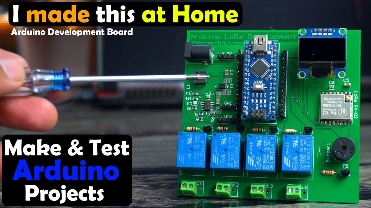
So, this is the final look of my designed Arduino Development board. Now, let’s go ahead and check if all the components on this development board are working.
Arduino Development board Testing:

For testing this board, I have connected a potentiometer with the analog pin A0 of the Arduino. I am going to print its value on the Oled display Module and when the value is going to exceed a certain threshold value the buzzer will turn ON and the 220Vac bulb connected to the relay will also turn ON.
Code for the Testing:
|
1 2 3 4 5 6 7 8 9 10 11 12 13 14 15 16 17 18 19 20 21 22 23 24 25 26 27 28 29 30 31 32 33 34 35 36 37 38 39 40 41 42 43 44 45 46 47 48 49 50 51 52 53 54 55 56 57 58 59 60 61 62 63 64 65 66 67 68 69 70 71 72 73 74 75 76 |
#include <SPI.h> // include libraries #include <Wire.h> #include <Adafruit_GFX.h> #include <Adafruit_SSD1306.h> int Buzzer = 8; int Potentiometer = A0; int relay1 = 4; int relay2 = 5; int relay3 = 6; int relay4 = 7; boolean relay1flag = false; boolean buzzerflag = false; #define SCREEN_WIDTH 128 // ORelay display width, in pixels #define SCREEN_HEIGHT 64 // ORelay display height, in pixels // Declaration for an SSD1306 display connected to I2C (SDA, SCL pins) #define ORelay_RESET -1 // Reset pin # (or -1 if sharing Arduino reset pin) Adafruit_SSD1306 display(SCREEN_WIDTH, SCREEN_HEIGHT, &Wire, ORelay_RESET); void setup() { // put your setup code here, to run once: Serial.begin(9600); Serial.println(" inside setup"); pinMode(Buzzer, OUTPUT); pinMode(Potentiometer, INPUT); pinMode(relay1, OUTPUT); pinMode(relay2, OUTPUT); pinMode(relay3, OUTPUT); pinMode(relay4, OUTPUT); display.begin(SSD1306_SWITCHCAPVCC, 0x3C); delay(2000); display.clearDisplay(); display.setTextColor(WHITE); } void loop() { // put your main code here, to run repeatedly: int PotValue = analogRead( Potentiometer); Serial.println(PotValue); display.clearDisplay(); display.setCursor(10,10); display.setTextSize(3); display.setTextColor(WHITE); display.print("V:"+String(PotValue)); display.display(); delay(1000); if (PotValue < 400) { digitalWrite(relay1, LOW); digitalWrite(Buzzer, LOW); delay(1000); } if ( ((PotValue >= 400)&& (PotValue < 600))) { digitalWrite(relay1, HIGH); delay(1000); } if (PotValue >= 600) { digitalWrite(relay1, HIGH); digitalWrite(Buzzer, HIGH); delay(1000); } } |
Practical Demonstration:
I am going to power up my Arduino development board using a 12Vdc adaptor.

I successfully tested the relays, Buzzer, and Oled display module.

I also used my 4S lithium Ion battery with this development board. The power supply on this development board accepts wide range of input voltage between 7 and 28 volts.

And by the way, in my next article and video, I will check the LoRa and its communication range using these different types of antennas. So, consider subscribing if you don’t want to miss any of my upcoming videos. So, that’s all for now.
Watch Video Tutorial:
Discover more from Electronic Clinic
Subscribe to get the latest posts sent to your email.


Can you share your schematic to me? I want to fabricate and try it in my hometown.