Types of Relays and how to use them? SPDT, DPDT, and Solid State Relay
how to use different types of relays spdt, dpdt, solid state
Table of Contents
Types of Relays, Description:
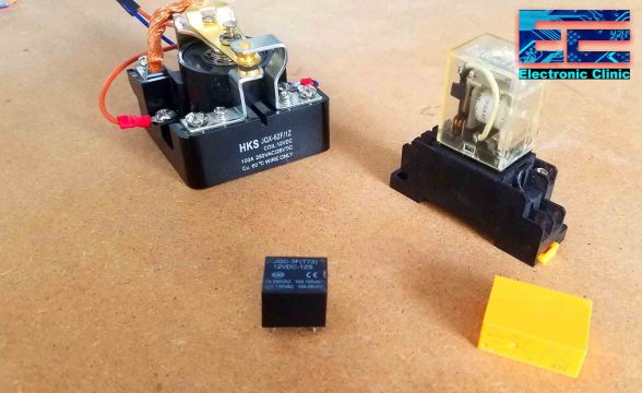
Types of Relays and how to use them- Relays are available in different shapes, sizes, voltage, and current ratings. We have mainly two types of relays electromechanical Relays and solid state relays. In this article I will explain 5 different types of relays designed for low and high load applications. In the image above you can see clearly, the white color relay is the SSR or Solid State Relay, while the remaining 4 relays are the Electromechanical relays. Out of these 4 relays 2 are of the type SPDT “Single Pole and Double Throw” and the other two relays are of the type DPDT “Double Pole and Double Throw”.
So let’s first start with the electromechanical relays and learn how to control these relays with and without the Arduino or any other controller board and in the end we will learn what is a solid state relay and how to use it to control high ampere loads.
Caution!!!
110/230VAC can be really dangerous. I highly recommend you should wear protective gloves and perform such experiments in the presence of a partner. Don’t touch the relay contacts, and other circuit parts when turned ON.
Without any further delay, let’s get started!!!
Amazon Purchase Links:
100A Power Relay, 12VDC SPDT Type Relay:
Fotek SSR-25 DA, Solid State Relay:
Other Tools and Components:
Super Starter kit for Beginners
PCB small portable drill machines
*Please Note: These are affiliate links. I may make a commission if you buy the components through these links. I would appreciate your support in this way!
Electromechanical Relay Types:
These are four different types of Relays; different in shapes, sizes, and pins configuration. It really doesn’t matter which type of the electromechanical relay you are using, the working principle is exactly the same. All you need is to connect the desired voltage with the relay coil contacts, which can be 5V to 48 Volts, and this is normally printed on the Relay. The type of relays I am using can be operated using 12Vdc and 24Vdc. When you connect the voltage with the relay coil pins you will hear the tuck sound.
To control these relays automatically using an Arduino board or ESP8266, or ESP32, or any other controller board, you will need to make a driver circuit. For the best understanding I will make one driver circuit which can be used to control all these relays. Let’s discuss each relay in detail.
12V SPDT Type Relay:
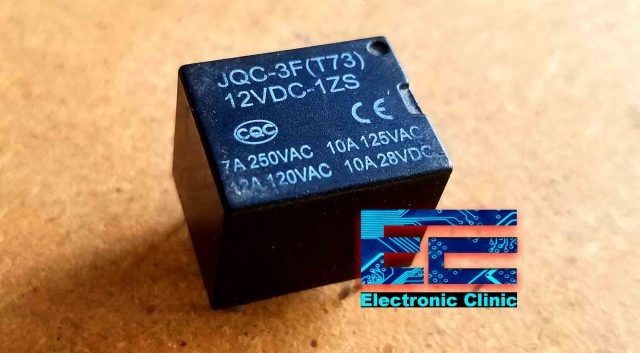
This is the 12V SPDT “Single Pole and Double throw” type relay. Normally, I use these types of relays for controlling AC loads. Relay specs are printed on the top. 12VDC means, that this relay can be controlled using 12Volts, this is the voltage used to energize the relay coil. This voltage remains completely isolated from the voltage connected with the Common and normally closed or normally open contacts of the relay.
At 250VAC it can handle AC load current up to 7Amps, 10A AC loads at 125VAC, and 12A AC loads at 120VAC. This relay can also be used to control DC loads up to 28VDC with load current up to 10Amps.
SPDT type Relay Pins Configuration:
The pins configuration of these types of relays are exactly the same, even if you are using a 5v Relay.
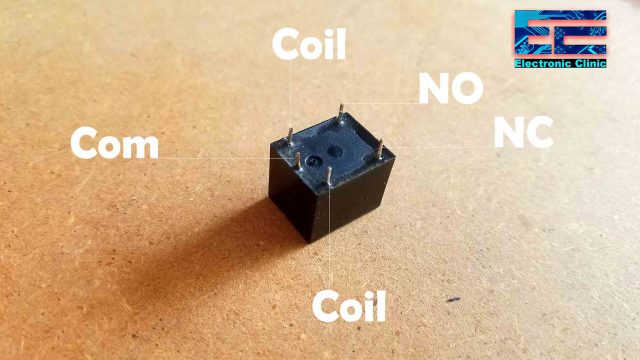
This relay has a total of 5 pins or contacts, 3 contacts on one side and 2 contacts on the other side. Among the three contacts on the left side, the middle one is the common contact, while the other two contacts are the coil contacts. On the right side we can see two contacts NC and NO. NC is the Normally Closed contact and NO is the Normally Open contact. The coil contacts are completely isolated from the Common contact, Normally Closed contact, and Normally Open contact. In simple words there is no physical connection between the coils contacts and the other relay contacts.
You can check this relay by connecting 12V and GND with the coils relay coil contacts. The relay coil has no polarity, so it really doesn’t matter which side of the coil you connect with the 12VDC and which side you connect with the GND.
Relay Driver Designing:
To control this relay automatically, we will need to make the driver circuit. With the help of the driver circuit then we can control the 12V relay using 3.3V and 5V compatible controller boards like for example ESP8266 and ESP32 which are 3.3V and Arduino boards are 5V.
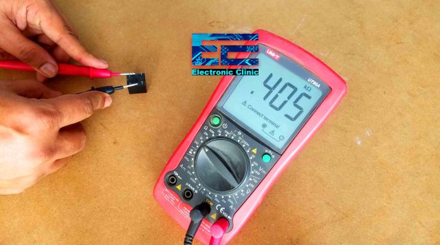
For the relay driver designing, you should know how much current is needed to energize the relay coil. For this you will need to find the coil resistance using a digital multimeter. Set the digital multimeter selection knob on the resistance. Connect the two probes of the digital multimeter with the coil contacts of the relay.
As you can see the coil resistance is 405 ohms. Now using the formula V = IR, we can find the current in milliamps, needed to energize the relay coil.
V = IR
I = V/R
I = 12/405
I = .029
I= 29mA
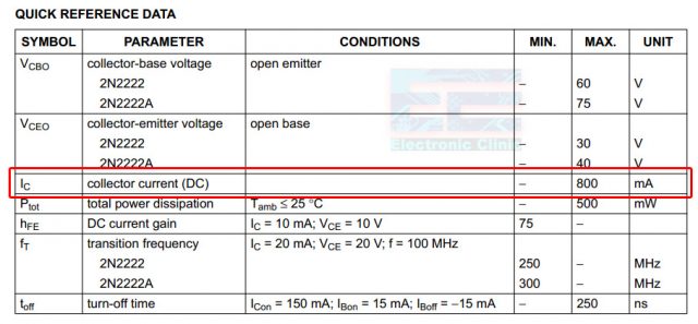
To energize this relay you will need 29mA. Now you can use any general purpose NPN or PNP type transistor whose collector current is greater than the relay coil current. My choice is 2n2222 NPN transistor, because if you check the datasheet you will find that this NPN transistor is capable of handling the current up to 800mA.
Moreover, the 2n2222 NPN transistor is cheap and it’s just like a cockroach available everywhere.
Relay Driver Circuit Diagram:
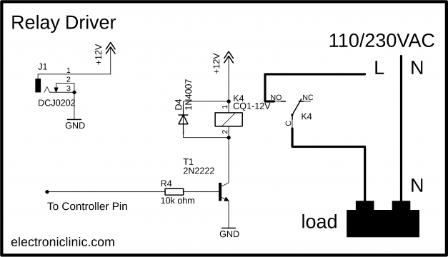
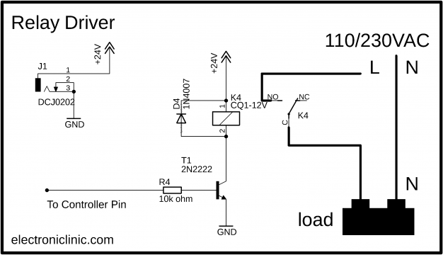
This is the relay driver circuit. One side of the relay coil is connected with the 12volts while the other side of the relay coil is connected with the collector of the 2n2222 NPN transistor. The emitter of the transistor is connected with the ground. The base of the transistor is connected with a 10k ohm resistor which is then connected with any I/O pin of the controller. A diode is connected across the two coil pins of the relay. This diode is used against the back EMF protection. AC or DC load is connected between the Common and Normally Open contacts. As you can see, a neutral wire is connected directly with the load, while the Live wire is connected with the load through a relay. So, by turning ON and turning OFF this relay the connected AC or DC load can be turned ON and Turned OFF.
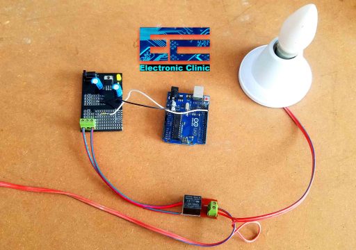
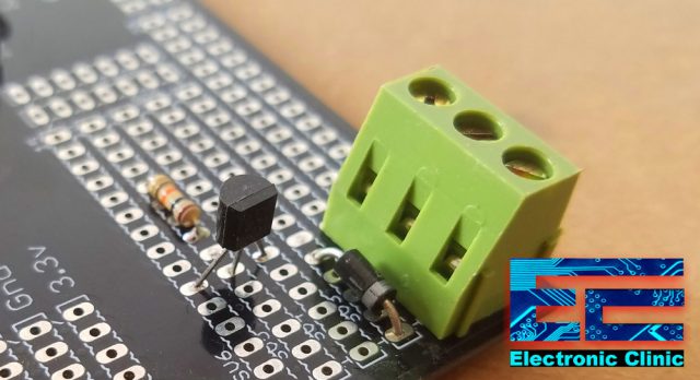
As I said earlier I will be using the same driver circuit for controlling all the relays. To make things easier for you I soldered the 2n2222 transistor, 10k resistor, and a terminal block.
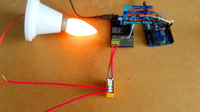
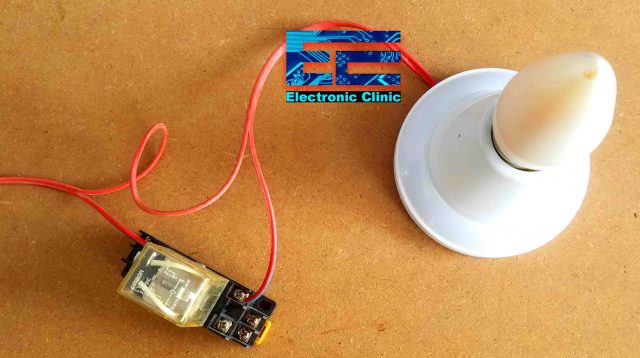
Connect the resistor with pin 13 of the Arduino and also the ground of the 12v power supply with the ground pin of the Arduino. Connect the two coil pins of the relay with the terminal block. Finally, I connected the AC load, in my case a Light Bulb. Now we will need to write a program to automatically turn ON and turn OFF this Bulb.
In the black circuit, you can see a voltage regulator and some decoupling capacitors. Don’t get confused with these components. If you have the 12V adaptor then there is no need to add the 12V regulator.
Program to control a 12V relay:
|
1 2 3 4 5 6 7 8 9 10 11 12 13 14 15 16 17 18 |
int relay1 = 13; void setup() { pinMode(relay1, OUTPUT); digitalWrite(relay1, LOW); } void loop() { digitalWrite(relay1, HIGH); delay(2000); digitalWrite(relay1, LOW); delay(2000); } |
This is a very basic program to control the relay connected with pin 13 of the Arduino Uno. I will be using the same program for controlling all the relays. I uploaded the above program and I was able to control the AC light Bulb automatically. For the practical demonstration watch video given at the end of this article.
12V SPDT Power Relay 100Ampere:
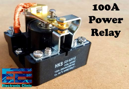
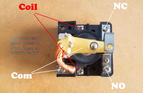
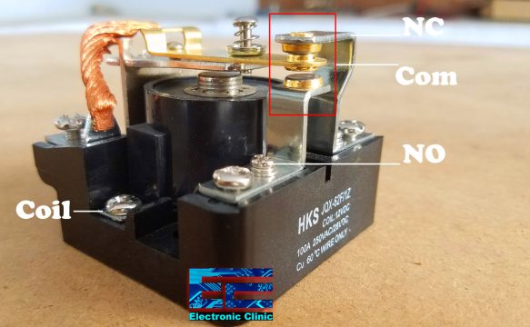
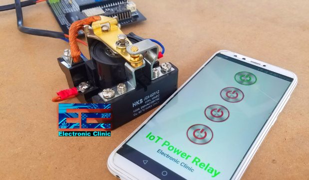
This is an SPDT 12V 100A Power Relay. This is the bigger version of the small 12V SPDT relay. This is quite obvious from the relay size, this Relay is designed for High ampere loads. You will normally find these types of relays in high wattage voltage stabilizers, and are used to control A/C plants, large Water Pumps etc.
This relay has a total of 5 contacts; All the 5 contacts of the Power Relay are clearly labeled. Just like the previously explained small SPDT type relay, this relay also has the same contacts. It has the coil contacts which are used to energize the relay coil. It has the common contact, normally closed contact, and normally open contact.
To operate this relay you need 12 volts, as the relay coil has no polarity so it really doesn’t matter which side of the relay coil is connected with the ground or 12Volts.
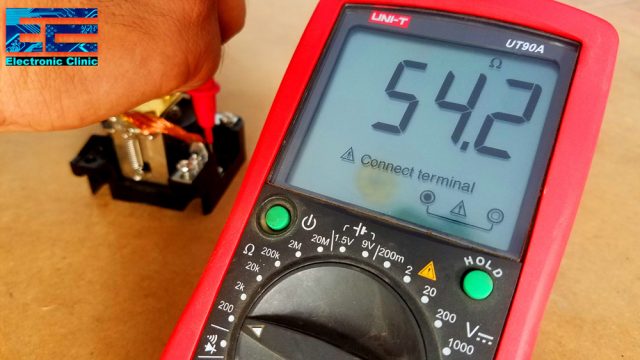
To operate this relay automatically we will need a driver circuit. First we find the relay coil resistance using a digital Multimeter.
As you can see the relay coil resistance is 54.2 Ohms, Now using the formula V = IR, we can find the current needed to energize the relay coil.
V = IR
I = V/R
I = 12/54.2
I = .221Amps
I = 221milliampere
So we need at least 221mA to energize the relay coil. As you know 2n2222 NPN transistor can handle current up to 800mA. So, we can use the same driver circuit for this relay as well, the only difference is, this time the relay is controlled using a 3.3V logic. I completed the soldering, and connected the relay coil contacts with the terminal block.
This time instead using the Arduino Uno, I decided to use the ESP32 WiFi + Bluetooth Module to control this Power relay using the Blynk application and the android cell phone application designed in android studio.
The android app, ESP32 code, and Blynk application designing is explained in another article “IoT Power Relay Project using ESP32 Wifi + Bluetooth, IoT Relay”.
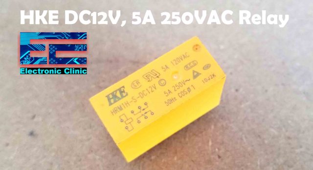
HKE DC12V, 5A 250VAC Relay:
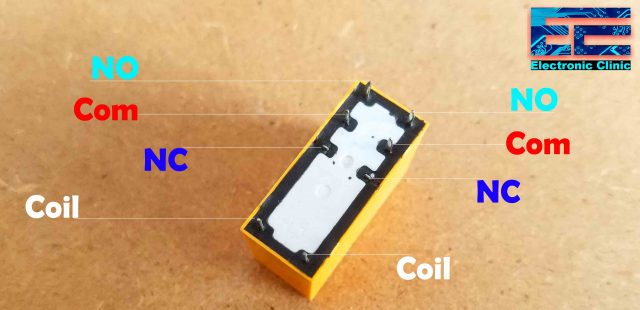
This is the HKE 12VDC DPDT “Double Pole and Double Throw” type relay. This DPDT type relay can be used to control AC loads up to 5Amps. As this is the DPDT type relay, so this relay can be used to control two AC loads. The pins configuration diagrams is given at the top. This relay has a total of 8 pins.
The first two pins are the coil pins. The next two pins are the normally closed, the next two pins are the common, while the last two are the normally open contacts. To control this relay automatically you will need the driver circuit.
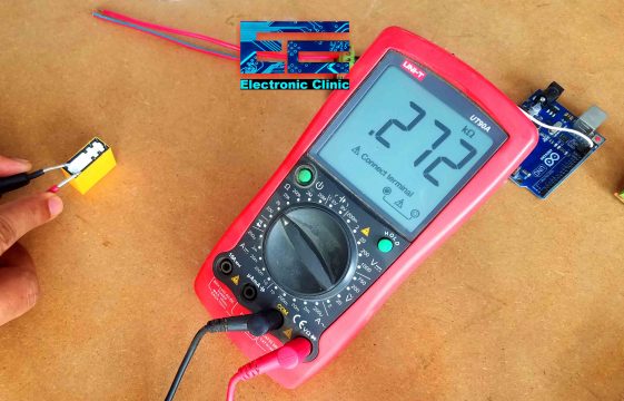
I started off by measuring the coil resistance and then using the formula V = IR, I calculated the current needed to energize the relay coil, which is 44milliampere. This relay can also be controlled using the same driver circuit.
V = IR
I = V/R
I = 12/272
I = .044A
I = 44mA
I connected the relay coil contacts with the Block terminal and one AC load with the common and normally open contacts.
This is how the final connections look. I will be using the same Arduino code. Currently, I am controlling only one load, if you want, you can connect another load as well.
Omron 24VDC Relay:
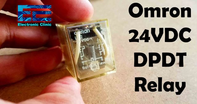
This is the Omron 24VDC DPDT type relay. This is the bigger version of the HKE 12VDC DPDT relay. The voltage and current specs are clearly printed on relay right side. This type of relay is normally used with PLCs. But with the help of a driver circuit it can be controlled using different voltages.
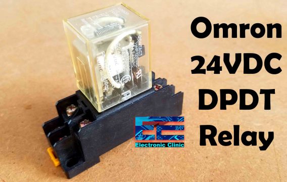
The Omron 24VDC DPDT type relay also comes with the base socket. The relay nicely sits in and there is no need of soldering. The relay contacts configuration diagram is given on the top and if you look closely, you will also find that the relay base socket also has the numbers. So, as per the relay contacts configuration diagram.
7 and 8 are the Relay coil contacts.
5 and 6 are the common contacts.
3 and 4 are the Normally Open contacts. And
1 and 2 are the Normally Closed contacts.
To control this relay automatically using a controller, you will need a driver circuit.
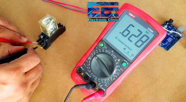
I started off by measuring the coil resistance and then using the formula V = IR.
V = IR
I = V/R
I = 24/628
I = .038A
I = 38mA
I calculated the current needed to energize the relay coil, which is 38milliampere. This relay can also be controlled using the same driver circuit. But this time we will connect 24VDC.
The AC load is connected with the relay 5 and 3 contacts. 5 is the common contact while contact number 3 is the Normally Open contact.
Currently I have connected a single load. If you want you can connect another AC or DC load with the other Common and Normally Open or Normally Closed contacts.
Fotek SSR-25 DA “Solid State Relay”:
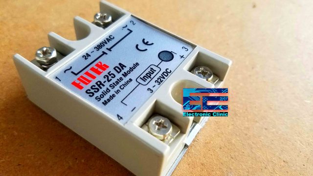
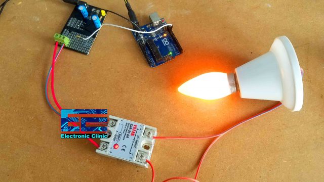
This is the Fotek SSR Solid State Relay capable of handling the AC load current up to 25 Ampere. It has no moving parts, so, you won’t hear any sound when you turn ON and turn OFF this relay. This Solid State Relay has a total of 4 contacts. AC loads are connected with the contacts 1 and 2. The AC voltage range is 24 to 380VAC. The input contacts 3 and 4 are used to turn ON and Turn OFF the relay. The input voltage range is from 3 to 32VDC. So, you can use any voltage from 3 to 32VDC to turn ON this relay. Contact 3 is the +ve while Contact 4 is the GND. Let’s control this relay using the driver circuit.
Solid State Relay connection diagram:
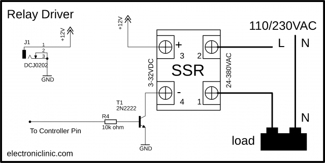
The 12VDC from the driver circuit is connected with the Plus contact of the solid state relay, and you don’t have to be worried as it accepts a wide range of input voltages from 3 to 32VDC. So this Solid State Relay can be safely operated using 12VDC. Connect the Ground contact of the Solid State Relay with the ground of the driver circuit. The two wires of the AC load are connected with the contacts 1 and 2.
There are so many other types of relays, but trust me if you try these relays I am sure you will be able to handle all the other types of relays without any problem. There is another type of the relay which is called the Hybrid Relay. A Hybrid relay is the combination of electromechanical relay and Solid state relay.
