IoT Power Relay Project using ESP32 Wifi + Bluetooth, IoT Relay
Last Updated on August 24, 2024 by Engr. Shahzada Fahad
Table of Contents
IoT Power Relay Project Description:
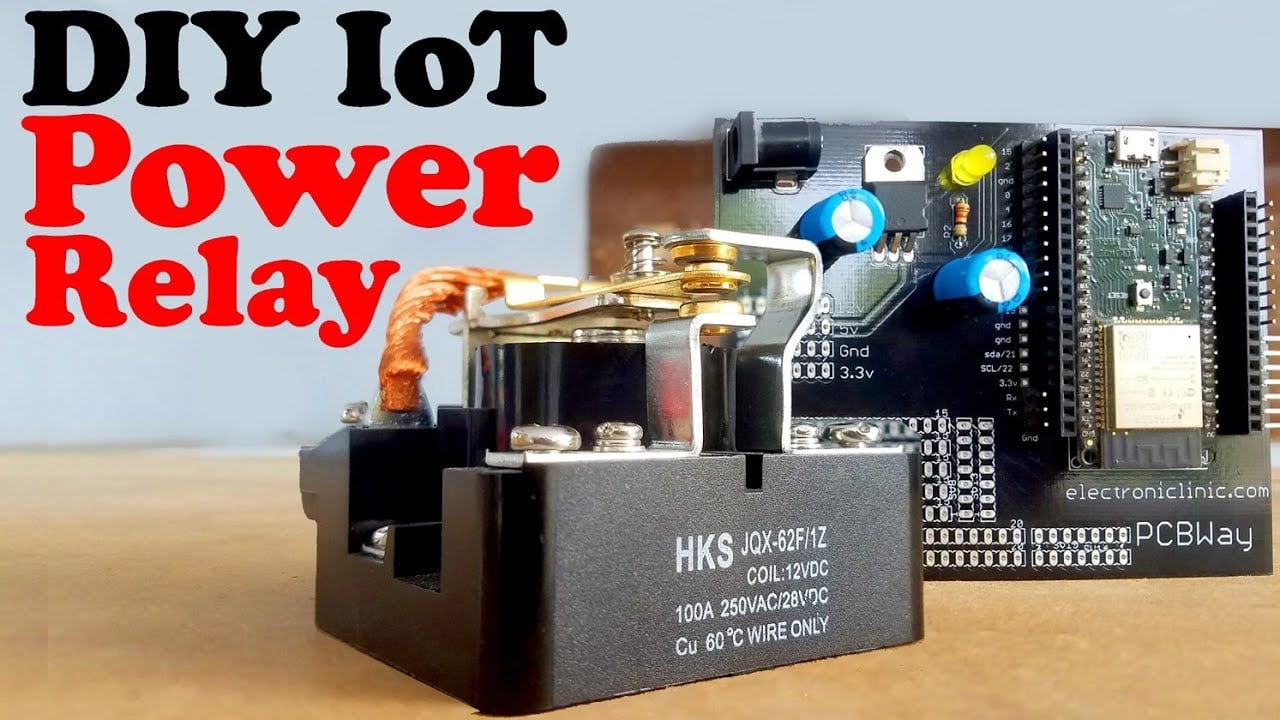
IoT Power Relay Project using ESP32 Wifi + Bluetooth Module- This DIY IoT Power Relay based on the ESP32 WiFi + Bluetooth module can be used to control the High Power Devices like for example Water Pumps, Air Conditioners, Heaters and other High Ampere loads. The best thing about this IoT Power Relay is that it can be controlled from two different sources.
About the Sponsor “PCBWay”:
High quality & Only 24 Hours Build time
This ESP32 Power Supply PCB board is sponsored and manufactured by the PCBway Company, which is one of the most experienced PCB and PCB assembly manufacturer. They create high-quality PCBs at reasonable prices, Only 5 dollars for 10 PCBs and 30 dollars in total for 20 PCBs assembly; besides this, the new members also get a 5 Dollars bonus. As you can see the quality is really great, the silkscreen is quite clear and the black solder mask looks amazing. I am 100% satisfied with their work.
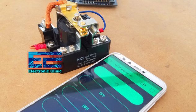
The best thing about this IoT Power Relay is that it can be controlled from anywhere around the world using WiFi technology. So, it really doesn’t matter how far you are, if you have the internet connection, you can turn ON and Turn OFF the Power Relay. The cell phone application is designed in Blynk which I will explain in a few minutes.
Download Android Application: iot power relay apk file
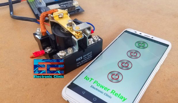
The Same Power relay can also be controlled over the Bluetooth using the Cell phone application designed in Android Studio. I have a very detailed tutorial on how to design your own android cell phone application using Android Studio.
For the Demonstration purposes, I will be controlling a Water Pump using the IoT Power Relay. To control the Water Pump over the WiFi connection all you need is; open your IoT Power Relay cell phone Application and start controlling the Water Pump. This application should be used only if you are far away.
If you are at home or near to the Power Relay then you can use your Bluetooth application to control the Water Pump. This also eliminates the risk of Electric Shock as there is no need to physically operate the switch. The IoT power relay can be used to control the Water Pump without any risk.
Imagine the situation, you are in a Washroom and the Water Tank is empty and you don’t feel like going downstairs, then all you need is to open your cell phone application and turn ON the water pump using the IoT Power Relay. If you are out of the Bluetooth range then you can use the other application that works with the WiFi. Isn’t it amazing? No physical contact with the High voltage switches, quite safe, and reliable.
In this tutorial, we will cover,
- Technical specifications of the Power Relay
- Power Relay Driver circuit designing and calculation
- Complete Circuit Diagram explanation
- IoT Power Relay Blynk Application designing
- ESP32 Programming, and finally
- Testing
Without any further delay, let’s get started!!!
Amazon Purchase Links:
ESP32 WiFi + Bluetooth Module(Recommended)
*Disclosure: These are affiliate links. As an Amazon Associate I earn from qualifying purchases.
About the 12V 100A SPDT Type Power Relay:
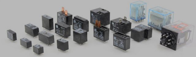
I have been using these small relays for controlling Light bulbs, Fans, and other low power devices. But these relays fail to work when used for controlling High ampere loads like Water pumps, ACs, Heaters and so on.

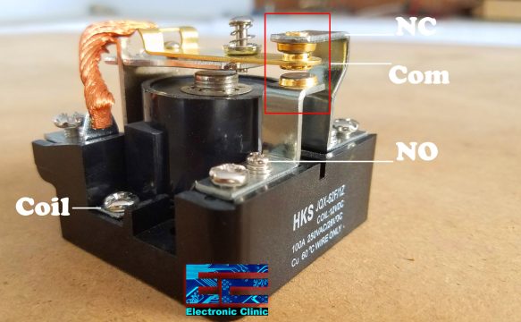
This is the Power Relay which I will convert into an IoT Power Relay using the ESP32 WiFi + Bluetooth Module. This is an SPDT 12V 100A Power Relay. This relay has a total of 5 contacts,
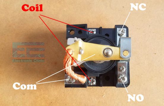
These are the coil contacts where we connect 12Vdc to energize the relay coil. This Copper plate is the Common contact which is connected with the metal through the copper wire. On the Upper Right side of the Power Relay is the Normally Closed contact, and on the Lower Right side is the Normally Opened contact. To operate this relay you need 12 volts, as the relay coil has no polarity so it really doesn’t matter which side of the relay coil is connected with the ground or 12Volts.
To control this Power relay using a controller you will need to design a driver circuit that can be used to control its output contacts using an electrical signal. You have a couple of choices, you can use a relay driver “ULN2003”, or you can use a transistor as the driver. In this tutorial, we will use a transistor to control this Power Relay.
Now the question is how we know which value transistor should be used? Well, it’s very simple. First, we find the relay coil resistance using a Digital Multimeter,
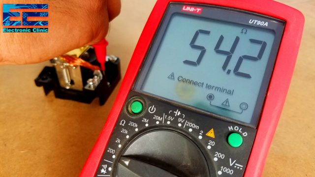
As you can see the relay coil resistance is 54.2 Ohms, Now using the formula V = IR, we can find the current needed to energize the relay coil.
I = V/R
I = 12/54.2
I = .221Amps
I = 221milliampere
So we need at least 221mA to energize the relay coil. Now we can use any general-purpose PNP or NPN transistor whose collector current is greater than 221mA.
If you look at the datasheet of the 2N2222 NPN transistor you will find that this transistor can bear up to 800mA which is perfect.
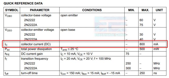
The 2n2222 NPN transistors are low cost and can be easily found in any electronics shop. Now let’s have a look at the complete circuit diagram of the IoT Power Relay.
IoT Power Relay Circuit Diagram:
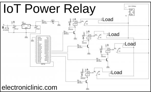
ESP32 based IoT Power Relay circuit diagram is very simple. Let’s first start with the regulated 5v power supply based on the LM7805 voltage regulator. This is the same 5v regulated power supply I have been using for the Nodemcu ESP8266 Wifi module. The reason I selected the ESP32 module is that it has a built-in Bluetooth Module.
J1 is the female power jack and this is where we connect a 12v adaptor, battery, or a solar panel. Two 470uf decoupling capacitors are connected at the input and output sides of the voltage regulator. A 330-ohm resistor is connected in series with a 2.5v led. This is a current limiting resistor. The output of the voltage regulator is connected with the 5v pin of the ESP32 module and the ground of the power supply is connected with the ground of the ESP32 module.
Currently, I have connected 4 Power relays. You can use a readymade relay module or you can follow the same exact connections and build a one by yourself. All the relays used in this project are of the type SPDT “Single Pole and double throw”. As you can see the connections of all the relays are exactly the same.
These are 12v relays and cannot be directly controlled using the ESP32 Module, So, that’s why we need a driver to control these relays. You can use a relay driver IC or you can use a 2n2222 NPN transistor and a 10k resistor. One pin of the relay coil is connected with the collector of the 2n2222 NPN transistor while the other pin of the relay coil is connected with the 12 volts. The emitter of the transistor is connected with the ground while the base is connected with the 10k ohm resistor.
Now to control these relays you simply need to connect these 10k resistors with the ESP32 I/O pins. In this project, I am using the GPIO pins 13, 12, 14, and 27. I will be using the same pins in the programming.
A Neutral wire from the 110/220Vac is connected directly with the neutral point of the AC Load, while the Live wire is connected with the Loads through the relays.
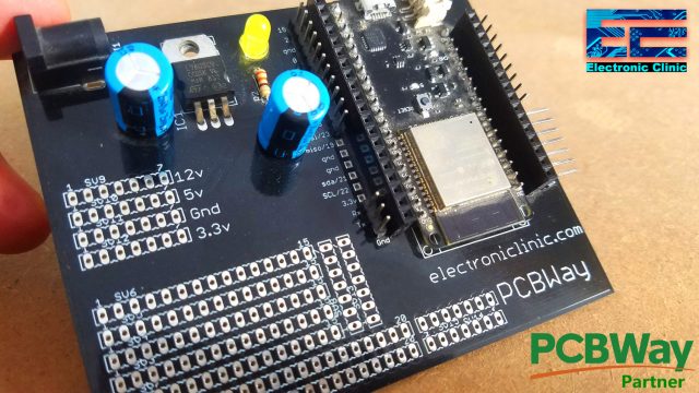
About the ESP32 Power Supply PCB board:
This is the ESP32 power supply board manufactured by the PCBWay Company, which I designed in my previous tutorial. You can see this board has the 12V, 5V, Gnd, and 3.3V rails. At the bottom side, you can also see so many holes, which can be used for soldering other electronic components. I will solder the 2n2222 NPN transistor, 10k Resistor, and a terminal block for connecting the 12v 100A Power Relay.
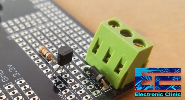
Finally, I soldered the 2n2222 NPN transistor and completed my connections as per the circuit diagram already explained.
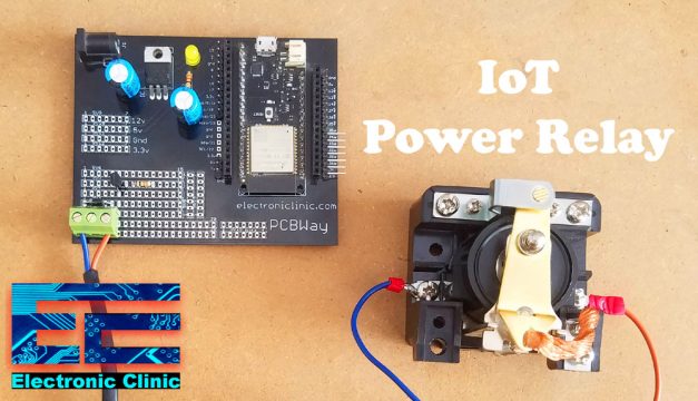
This is how the IoT Power Relay looks after completing all the connections. Now let’s make the Blynk application.
Note: this old version of the Blynk app is no more functional. For the blynk mobile App setup and Blynk.cloud dashboard setup ready my article on the New Blynk V2.0. In this article I have explained how to migrate your projects from Blynk 1.0 to the new Blynk V2.0. You can also watch the video.
IoT Power Relay BLYNK APPLICATION DESIGNING:
- First of all, open the Blynk application.
- Click on the new project and enter the project name as “IoT Power Relay”.
- Click on the choose device and select ESP32 Dev Board.
- Make sure the connection type is set to WIFI.
- Finally, click on the create button, an authentication token will be sent on your email id, which later will be used in the IoT Power Relay ESP32
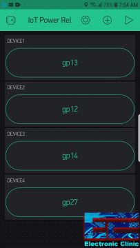
- Click anywhere on the screen and add 4 buttons. Drag and drop, if you want to adjust the size.
- Click on the first button, Set the name as Device1, select GP13, Set mode to SWITCH, and change the font size if you want.
- Click on the second button, Set the name as Device2, select GP12, Set mode to SWITCH, and change the font size if you want.
- Click on the third button, Set the name as Device3, select GP14, Set mode to SWITCH, and change the font size if you want.
- Click on the fourth button, Set the name as Device4, select GP27, Set mode to SWITCH, and change the font size if you want.
That’s it our IoT Power Relay Blynk application is ready.
IoT Power Relay, ESP32 Programming:
/*
https://www.electroniclinic.com/
ESP32 Board Manager Installation
https://www.electroniclinic.com/esp32-arduino-ide-board-manager-installation-espressif-esp32-wroom/
Download Libraries:
|
1 2 3 4 5 6 7 8 9 10 11 12 13 14 15 16 17 18 19 20 21 22 23 24 25 26 27 28 29 30 31 32 33 34 35 36 37 38 39 40 41 42 43 44 45 46 47 48 49 50 51 52 53 54 55 56 57 58 59 60 61 62 63 64 65 66 67 68 69 70 71 72 73 74 75 76 77 78 79 80 81 82 83 84 85 86 87 88 89 90 91 92 93 94 95 96 97 98 99 100 101 102 103 104 105 106 107 108 109 110 111 112 113 114 115 116 117 118 119 120 121 122 123 124 125 126 127 128 129 130 131 132 133 134 |
*/ #include "BluetoothSerial.h" #define BLYNK_PRINT Serial #include <BlynkSimpleEsp32.h> #if !defined(CONFIG_BT_ENABLED) || !defined(CONFIG_BLUEDROID_ENABLED) #error Bluetooth is not enabled! Please run `make menuconfig` to and enable it #endif BluetoothSerial SerialBT; long int Bluedata; int relay1 = 13; long int password1 = 98421615;// Relay1 ON long int password11 = 96951628;// Relay1 OFF int relay2 = 12; long int password2 = 74151525; // Relay2 ON long int password21 = 45614787; // Relay2 OFF int relay3 = 14; long int password3 = 84515822; // relay3 ON long int password31 = 81599922; // Relay3 OFF int relay4 = 27; long int password4 = 81426337; long int password41 = 88428399; // for IOT // You should get Auth Token in the Blynk App. char auth[] = "szETZohB3MtHIL0y7BJGarXPQbZCkafa"; // Your WiFi credentials. // Set password to "" for open networks. char ssid[] = "AndroidAP7DF8"; char pass[] = "electroniclinic"; void setup() { Serial.begin(115200); SerialBT.begin("ESP32_Electronic_Clinic"); //Bluetooth device name Serial.println("The device started, now you can pair it with bluetooth!"); pinMode(relay1, OUTPUT); digitalWrite(relay1, LOW); pinMode(relay2, OUTPUT); digitalWrite(relay2, LOW); pinMode(relay3, OUTPUT); digitalWrite(relay3, LOW); pinMode(relay4, OUTPUT); digitalWrite(relay4, LOW); Blynk.begin(auth, ssid, pass); } void loop() { Blynk.run(); if (Serial.available()) { SerialBT.write(Serial.read()); } if (SerialBT.available()) { Bluedata = SerialBT.parseInt(); } delay(20); // Serial.println(Bluedata); if ( password1 == Bluedata ) { digitalWrite(relay1, HIGH); SerialBT.println("Relay 1 is turned ON"); Bluedata = 0; delay(100); } if ( password11 == Bluedata ) { digitalWrite(relay1, LOW); SerialBT.println("Relay 1 is turned OFF"); Bluedata = 0; delay(100); } // RELAY 2 if ( password2 == Bluedata ) { digitalWrite(relay2, HIGH); SerialBT.println("Relay 2 is turned ON"); Bluedata = 0; delay(100); } if ( password21 == Bluedata ) { digitalWrite(relay2, LOW); SerialBT.println("Relay 2 is turned OFF"); Bluedata = 0; delay(100); } // RELAY 3 if ( password3 == Bluedata ) { digitalWrite(relay3, HIGH); SerialBT.println("Relay 3 is turned ON"); Bluedata = 0; delay(100); } if ( password31 == Bluedata ) { digitalWrite(relay3, LOW); SerialBT.println("Relay 3 is turned OFF"); Bluedata = 0; delay(100); } // RELAY 4 if ( password4 == Bluedata ) { digitalWrite(relay4, HIGH); SerialBT.println("Relay 4 is turned ON"); Bluedata = 0; delay(100); } if ( password41 == Bluedata ) { digitalWrite(relay4, LOW); SerialBT.println("Relay 4 is turned OFF"); Bluedata = 0; delay(100); } } |
IoT Power Relay Code Explanation:
Before, you start the programming; first of all, make sure you download all the necessary libraries.
The purpose of this code is to control the IoT power Relays using the Bluetooth application and the IoT supported application designed in Blynk.
int relay1 = 13;
long int password1 = 98421615;// Relay1 ON
long int password11 = 96951628;// Relay1 OFF
int relay2 = 12;
long int password2 = 74151525; // Relay2 ON
long int password21 = 45614787; // Relay2 OFF
int relay3 = 14;
long int password3 = 84515822; // relay3 ON
long int password31 = 81599922; // Relay3 OFF
int relay4 = 27;
long int password4 = 81426337;
long int password41 = 88428399;
Out of these 4 relays I will be using only one Power Relay, if you want you can increase or decrease the number of relays used. Each relay is controlled using a strong password. The 4 Power Relays are connected with the ESP32 GPIO pins 13, 12, 14, and 27.
char auth[] = “szETZohB3MtHIL0y7BJGarXPQbZCkafa”;
This is the authentication code which was sent via email, I simply copied and paste it over here.
char ssid[] = “AndroidAP7DF8”;
char pass[] = “jamshaid”;
These are the WiFi credentials, the WiFi router name and the password.
Inside the void setup() function, I activated the Serial communication using the Serial.begin() function which is used for the debugging purposes. I set all the relays as output using the pinMode() function.
Inside the void loop() function, we have the Blynk.run() function and some code that monitors if the ESP32 module has received any data through the Built-in Bluetooth Module. The received data is compared with different passwords, if the received data matches with any of the already stored passwords the desired power relay is turned ON or Turn OFF.
For the practical demonstration and step by step explanation watch video tutorial given below. If you have any questions regarding this project let me know in a comment. Don’t forget to Subscribe to my Website and YouTube channel “Electronic Clinic”.
Watch Video Tutorial:
Discover more from Electronic Clinic
Subscribe to get the latest posts sent to your email.


Nice blog! Your blog is very informative. Shopping for wifi Relays ? Here is our pick for the absolute best wifi relays that money can buy which are available in australia.
Buy shelly wifi relay online