Arduino ULN2003 Driver to control a relay
Last Updated on August 16, 2024 by Engr. Shahzada Fahad
Table of Contents
Arduino ULN2003, Description:
Arduino ULN2003– Today’s Tutorial is about the ULN2003A, which is most commonly used in electronics circuits. One of its most common uses is that uln2003 is used as a relay driver. At the same time, you can control 7 relays. So far, I have been using 2n2222 NPN transistors, resistors, and diodes for controlling the relays.
If you look at this circuit, this circuit consists of 7 relays, seven transistors, seven diodes, seven resistors, a lot of soldering, needs more space, difficult troubleshooting, which results in an increased price. But what if uln2003 was used in this circuit? So we can reduce the PCB size, we can reduce its making time, we can reduce its price.
So in this tutorial, you will learn how to use uln2003 with Arduino to control a relay, an led “light-emitting diode”, A solenoid Valve, etc. For the best understanding, we will be studying the datasheet of uln2003, then we will make a simulation in Proteus and write an Arduino program to control uln2003 automatically, and then we will practically test the design on a breadboard. So let’s get started…
Amazon Links:
Arduino Nano USB-C Type (Recommended)
*Disclosure: These are affiliate links. As an Amazon Associate I earn from qualifying purchases.
ULN2003 Driver
If you open the datasheet of the ULN2003 you can find the following information.
Features
- 500-mA-Rated Collector Current (Single Output)
- High-Voltage Outputs: 50 V
- Inputs Compatible With Various Types of Logic
- Relay-Driver Applications
Its most common Applications are
- uln2003 is actually famous as Relay Drivers but also used for controlling
- Stepper and DC Brushed Motors
- Lamps
- led Displays
- Line Drivers and
- Logic Buffers
Pin Configuration and functions:
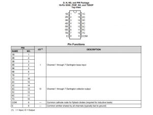
Uln2003 has a total of 16 pins. pin number8 which are labeled as E is connected with the Ground. and pin number 9 which is labeled as COM is connected with the supply voltage. If you are controlling 12v relays then connect 12v with this pin. The pin’s labeled as 1B, 2B up to 7B are the input pins and will be connected with the Arduino Uno / mega digital pins. While the pins labeled as 1C, 2C up to 7C are the output pins and will be connected with relays, led’s, solenoid valves, etc as per the needs.
Specifications:
VCC collector-emitter voltage maximum 50volts
and peak collector current is 500 milli amps.
So

This is the uln2003 ic which we will be using today for controlling an Led, Relay and a solenoid valve. ULN2003 is a seven-channel Darlington array used to interface microcontrollers to high voltage, high current devices such as solenoids, lamps, relays, etc. It has the capacity to drive 500mA into a single channel, But wait ..it doesn’t mean you can get 500mA on all the seven channels when all the seven channels are active. Well, you can get up to 250mA per channel if four of the seven channels are active and you can get 125 mA per channel if all the seven channels are active.
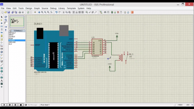
Arduino ULN2003 Proteus Simulation:
ULN2003 Arduino Programming:
this is the program, written for controlling uln2003. The same program will be used for controlling an led, 12v SPDT type relay, and a 12v solenoid valve. So, first of all, we start by defining some pins
|
1 |
int uln_1B = 13; |
this instruction means that the uln2003 pin number1 which is 1B is connected with Arduino / mega pin number13. As no spaces are allowed in the variable names so that’s why I used an underscore sign. and one more thing, never use numbers at the beginning of variable names as it will generate an error. so you have to follow some rules like no spaces are allowed, no number in the beginning , and never use same variable names for different pins. a variable name should be unique. in simple words as your name is unique among your brothers and sisters. and then
|
1 2 3 4 5 6 7 8 9 10 11 12 13 14 15 |
int uln_2B = 12; int uln_3B = 11; int uln_4B = 10; int uln_5B = 9; int uln_6B = 6; int uln_7B = 5; void means that this function is not returning any value and the empty parenthesis means that this function is not taking any argument as the input. void setup() { pinMode(uln_1B, OUTPUT); } |
pinMode is a function and it takes two arguments as the inputs, the pin number or pin name and the status which can be INPUT or output. as we are using unl2003 for controlling, an led, a relay and a solenoid valve so that’s why it is set to OUPUT.
Right now I am using only one channel of the uln2003, the reason for using one channel is that I want to show you guys how you can use the same channel to control different loads.
|
1 2 3 4 5 6 7 8 9 |
void loop() { digitalWrite(uln_1B, HIGH); delay(1000); // delay of 1 second digitalWrite(uln_1B, LOW); delay(3000); } |
Now all you need is to upload the program and do the connections as per the simulation diagram. For the final testing watch video given below.
Watch Video Tutorial:
Discover more from Electronic Clinic
Subscribe to get the latest posts sent to your email.


Hi…Free wheel diode across relay coil required while we connect indutive load?
Hello, normally yes, but in this case the ULN2003 has them internally.
Thanks for an awesome post. This really helped me in designing my LED driver circuit board as a lot of similar posts were incomplete or a little unclear.