Examples Solution of Batten Wiring Estimates
Last Updated on December 30, 2023 by Engr. Shahzada Fahad
Table of Contents
Batten Wiring Estimates
Batten wiring is an electrical installation method where insulated wires are run over wooden battens. Predominantly used in the early to mid-20th century, this method has largely been replaced by more advanced wiring systems in modern construction but still finds relevance in certain situations due to its simplicity and cost-effectiveness.
The core element of batten wiring is the wooden batten, which is a strip of wood used as the base to which the wires are affixed. These battens are typically treated with a preservative to prevent moisture absorption and reduce the risk of fire. The wires, usually single-core, are laid out along the batten and secured using brass clips at regular intervals. These clips ensure the wires are held firmly in place and reduce the risk of damage or disconnection.
One of the key advantages of batten wiring is its accessibility. Since the wires are exposed, it’s easy to identify and rectify faults or make alterations. This aspect makes batten wiring particularly suitable for temporary installations or in workshops and garages where frequent changes might be required. Moreover, its cost-effectiveness is a significant factor, as the materials required for batten wiring are relatively inexpensive compared to modern concealed wiring.
However, batten wiring also has notable drawbacks. It is not aesthetically pleasing and does not blend well with modern interior designs. More importantly, the exposed nature of the wiring makes it vulnerable to physical damage, which can lead to short circuits or fire hazards. This vulnerability also extends to environmental factors like moisture and dust, which can deteriorate the insulation over time, increasing the risk of electrical hazards.
In summary, while batten wiring is a testament to the evolution of electrical installation techniques, its use in contemporary settings is limited due to advancements in safety and aesthetic preferences. It remains, however, a useful and cost-effective method for certain specific applications where these modern requirements are not a priority.
Example 1:
A room has a vertical run of batten of 3m with a switch at the lower end and a lamp at the upper end. The supply is given by another batten 2m place horizontally two meter above the switchboard. Draw a diagram indicating the place of screws to fasten the batten on wall. Prepare an estimate of material required for this wiring without missing any minor item.

Solution;
(1). Estimate of wooden Screw 1 ½”
We know that
(i). Distance between two screws should be 1 ft or 3 screws per meter.
(ii). On each batten end, wooden screw 1 ½” will be used on distance 2.5 cm (1”)
Screws on 2m horizontal batten = 2 x 3 = 6 + 1 (for end) =7
Screws on 3m vertical batten = 3 x 3 = 9 + 1 (for end) = 10
Total screws = 17
(2). Estimate of PVC Cable 3/ .029”
(Formula: Distance x Number of wires)
Vertical position = 3 x 2 = 6 m
Horizontal position = 2 x 2 = 4 m
Extra cable used in switch board @ 0.25 m / end = 2 x 0.25 = 0.5 m
Extra cable used in round block of lamp @ 0.1 m / end = 2 x 0.1 = 0.2 m
Extra cable for 2 supply ends = 2 x 0.1 = 0.2 m
Total cable = 6 +4 +0.5 +0.2 +0.2 = 10.9 m
(3). Batten Clips 1 ½”
= Length of batten x 20 = 5 x 20 = 100 Nos. = 100/ 50 = 2 packet
(4). Nails ½”
= No. of nails = 100 No. = 100 / 4 = 25 gm (since 4 nails = 1 gm)
Material List
| Material | Quantity | Material | Quantity |
| (1). PVC cable 3/.029”
(2). Switch single way 5A (3). Lamp holder 5A (4). Batten ½” (3+2) (5). Clip 1 ½” (6). Nail ½” (7). Wooden board 4” x 4” |
10.9 m
1 No. 1 No. 5 m 2 Pkts 25 gm 1 No. |
(8). Round block
(9). Screws ½” (10). Screws 1 ½” (11). Screws 2 ½” (for board and round block) (12). Rawal plug (equal to screw 1 ½” + 2 ½”) |
1 No.
4 No. 17 No. 4 No.
21 No.
|
Example 2;
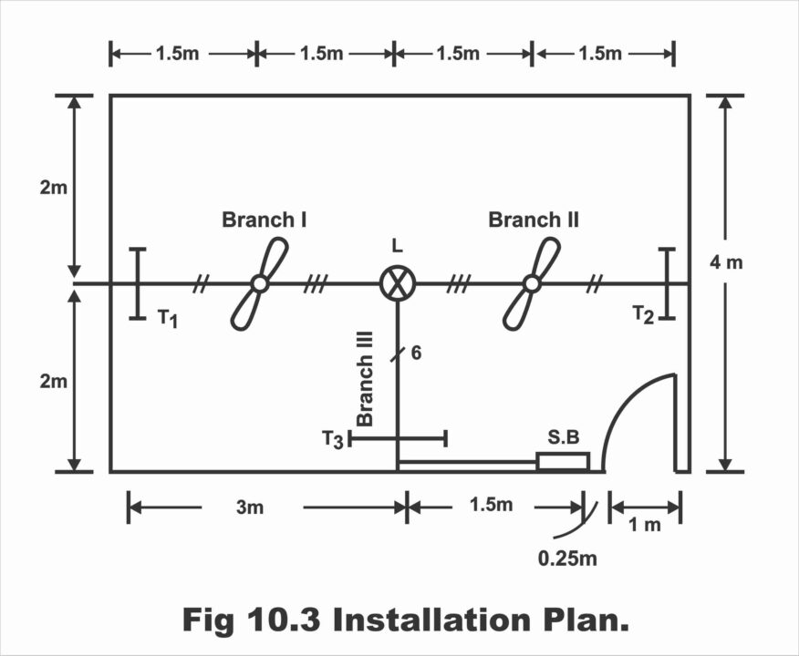
A drawing room of 6 m x 4 m, the plan of which is given below is required to be provided with electrical batten wiring. Study the requirements of electrical points suitably, mark the position of switch board and electrical points suitably. Solve the estimate in the following sequence;
Figure 10.2

Figure 10.3
(a) Draw the installation plan showing supply path to each point
(b) Draw the wiring diagram
© Calculate tubes and fans required
(d) Mark cable and batten estimating with necessary items
(e) Prepare a complete list of material with complete specification of each item
Solution;
(a) Installation plan is shown in figure 10.3
(b) Wiring diagram is shown in figure 10.4
Figure 10.4

© Tubes and fans required;
Suppose
Illumination required (E) = 100 Lux (Drawing room)
Depreciation factor (D.F) = 0.6
Utilization factor (U.F) = 0.5
Flux = EA / U.F x D.F = 100 x 6 x 4 / 0.5 x 0.6 = 8000 lumen
Tube 40 watt (day light) required = 3 Nos. = 2120 x 3 = 6360 lm
Lamp 100 watt (see data table) = 1 No. = 1750 lm
Total = 8110 lm
This scheme is suitable because the lumens emitted are nearly equal to the lumens required
Fans Required
Area of room = 6m x 4 m
Usually, rooms are non- ventilated
So, suitable size of ceiling fan used for the room = 48”
No. of fans required (Non – ventilated room) = Area of room/ Area covered by a fan 48”
= 6 x 4 / 3.67 x 3.67 = 1.78 2 Nos.
Wiring Circuits
There are eight points along with two sockets in the given room. We know that ten points or up to 800 watts load can be controlled on the circuit. Therefore, one circuit is enough.
(d). Cable estimate;
We know that
Height of switch board = 1.5 m
Height of switch board to wiring height = 1.25 m
Since ceiling height from floor = 4 m
Therefore, the height from wiring to ceiling = 1.25 m
Branch I;
Length of cable from T1 to lamp x No. of cables
= (1.25 m x 2) + (1.5 m x 2) + (1.5 m x 3)
= 2.5 + 3+ 4.5 = 10 m
Branch II;
From T2 to lamp
= (1.25 m x 2) + (1.5 m x 2) + (1.5 m x 3)
= 2.5 + 3+ 4.5 = 10 m
Branch III;
From lamp to switch board
Note; At the point of lamp, neutral wire is combined
= 2 m x 6) + (1.25 m x 6) + (1.5 m x 7) + (1.25 m x 7)
= 12 + 7.5 + 10.5 + 8.75 = 38.75 m
Total cable = 10 + 10+ 38.75 = 58.75 m
Wastage @ 10% = 10/100 x 58.75 = 5.87 m
Extra cable used for connections @5% = 2.94 m
Grand total with wastage = 67.56 m
Batten Estimate
Wooden Batten ½” (for max 3 Cables)
Branch I; 1.25 + 1.5+ 1.5 = 4.25 m
Branch II; 1.25 + 1.5 + 1.5 = 4.25 m
Branch III; (2 x 2) + (1.25 x 2) + 1.5 + 1.25 = 9.25 m
Total 17.75 m
Wastage @ 10% = 10 / 100 x 17.75 = 1.77 m
Grand total with wastage = 19.52 m
= 20.00 m
Wooden Batten ¾” (for max. 5 Cables)
Branch III; 1.5 + 1.25 = 2.75 m
Wastage @10% = 0.275 m
Grand total with wastage = 3.025m
= 3 m
Clip Estimate
Batten clips installed on batten @ 20 nos./ meter approx.
Clips 1 ½” required on batten ½” = Total length of batten ½” x 20
= 20 x 20 = 400 nos.
=400/ 50 = 8 Packets
Clip 1 ½” required on batten ½” = Total length of batten ½” x 20
=20 x 20 = 400 nos.
=400 / 50 = 8 packets
Clip 2” required on batten ¾” = Total length of batten ¾” x 20
=3 x 20 = 60 nos.
= 60 / 50 = 1.2 packets
Nails ½”; (No. of clips 1 ½” +2”)
=400 +60+460 Nos.
=460/ (4 x 1000) = 0.115 Kg (since 4 nails = 1 gm)
Wooden screws;
Screw ½” = 2 (No. of ceiling roses + No. of holders)
= 2 (6+1) = 14 Nos. = 1.2 dozen
Screw 1 ½” = Length of batten (½ + ¾) x 3
= (20 + 3) x 3 = 69 Nos. 69 / 12 = 5.75 = 6 dozen
Screw 2” = (No. of tubes x 2) = 3 x 2 = 6 No. = 0.5 dozen
Screw 2 ½” = No. of boards x 4) + (No. of round block x 2)
=1 x 4 + 6 x 2 = 16 Nos.
=16/12 = 1.3 dozen
Rawal Plug;
Equal to No. of screws = (1 ½” + 2” + 2 ½”)
= 69 + 6 + 16 = 91 Nos.
= 91 / 25 = 4 packets
Note; Two 2 – pin socket separately controlled with 2 switches are installed on switch board.
(e) Cost Estimate
| S. No | Description of Material with Specification | Quantity Required | Unit | Rate
(Rs.) |
Amount
(Rs.) |
| 1 | PVC cable 3 /.029” single core | 68 | Meter | 6 | 408 |
| 2 | Wooden batten ½” | 20 | Meter | 5 | 100 |
| 3 | Wooden batten ¾” | 3 | Meter | 8 | 24 |
| 4 | Clip 1 ½” | 8 | Packet | 3 | 24 |
| 5 | Clip 2” | 1 | Packet | 4 | 4.00 |
| 6 | Wooden screw ½” | 1.2 | Packet | 4 | 4.00 |
| 7 | Wooden screw 1 ½” | 6 | Dozen | 3 | 18 |
| 8 | Wooden screw 2” | 0.5 | Dozen | 6 | 3.00 |
| 9 | Wooden screw 2 ½” | 1.3 | Dozen | 8 | 10.40 |
| 10 | Rawal plug | 4 | Packet | 10 | 40.00 |
| 11 | Single way switch 5Amp Piano | 8 | No. | 10 | 80.00 |
| 12 | 2 pin socket 5 Amp Piano | 2 | No. | 10 | 20.00 |
| 13 | Ceiling fan 5 Amp | 5 | No. | 12 | 60.00 |
| 14 | Dimmer fan | 2 | No. | 60 | 120 |
| 15 | Wooden board 8” x 10” (fiber sheet) | 1 | No. | 40 | 40 |
| 16 | Wooden board 4” x 4” (fiber sheet) | 6 | No. | 10 | 60 |
| 17 | Nails ½” | 0.115 | Kg | 100 | 11.50 |
| 18 | Ceiling fan 48” | 2 | No. | 1400 | 2800 |
| 19 | Tube light 40-watt day light | 3 | No. | 250 | 750 |
| 20 | Lamp 100 watts | 1 | No. | 15 | 15 |
| 21 | Batten lamp holder 5A | 1 | No. | 10 | 10 |
| 22 | Fan hook | 2 | No. | 10 | 20 |
| Total
Labor charges @10% = 10/100 x 3951.90 Grand total |
Rs. 4621.90
Rs. 462.19 Rs. 5084.09 Rs. 5084/= |
Example 3;
A room and a verandah, the plan of which is given below are required to be provided with electrical wiring. Study the requirements of electrical points suitably and mark the location of energy meter, main switch, switchboards, and electrical points suitably. Solve the estimate in the following sequence;
(a). Draw the installation plan showing supply path to each point
(b). Draw the wiring diagram starting from energy meter
(c). Calculate the total length of batten of various sizes and the total length of wire required for wiring the building in batten system of wiring.
(d). Prepare a complete list of material with complete specification of each item
Solution;
The requirement of points in a normal room of this size is two light points, one fan and one socket outlet (to be installed in room). The requirement of points in verandah should be one socket outlet, one fan, one lamp point in verandah, and one lamp for general illumination outside the building.
Assume;
(a) Height of ceiling from floor = 3.5 meters
(b) Height of horizontal run from floor = 3.0 meters
© Height of SB from floor = 1.5 meter
(d) Location of main board, i.e., energy meter and main switch to be 0.5 meters inside verandah on room wall
(e) All dimensions in meters
(f) Wires and conduit in thickness of wall not to be taken into account
Calculation of Load
Lamps = 3 x 60 watt = 180 watts
Fans = 2 x 60 watt = 120 watts
Socket outlet 5 Amp. = 2 x 100 watt = 200 watts
Fluorescent tube = 1 x 40 watt = 40 watts
Total connected load = 540 watts
Load in Amps. Watts / Volts = 540 W / 230 V = 2.4 Amps approx.
Selection and Rating of Main Switch
As the total load in the building is 2.4 amps. when all points are switched on at one time, it is therefore, suggested that;
“A DPIC (Double Pole Iron Clad) Main Switch of 5 Amp rating, 250 V grade “should be used.
Selection and Rating of Distribution Board
The selection of distribution board (fuse box) is always on the basis of number of electrical points in the said building. Here in the building under estimate, there are only eight light / fan 5 Amp socket points. Therefore, no distribution board will be used.
Figure 10.5

Figure 10.6

Calculations for length of batten
From main board to HR = 1.5 mt. 13 mm x 13 mm 2 wires
From SB1 to HR = 1.5 mt. 37 mm x 13 mm 6 wires
From SB2 to HR = 1.5 mt. 25 mm x 13 mm 4 wires
From HR above main board to L1 = 1.5 mt. 13 mm x 13 mm 2 wires
From L1 to F1 = 0.5 + 1.5 … = 2.0 mt. 19 mm x 13 mm 3 wires
From F1 to L2 =1.5 +0.5 … = 2.0 mt. 13 mm x 13 mm 2 wires
From HR above SB2 to F2 = 0.5 + 2.0 = 2.5 mt. 25 mm x 13 mm 4 wires
From F2 to L3 = 2.0 +0.5 … = 2.5 mt. 13 mm x 13 mm 2 wires
From F2 to tube = 2.0 +0.5 … = 2.5 mt. 13 mm x 13 mm 2 wires
Total length of batten of size (as calculated above);
13 mm x 13 mm = 1.5 + 1.5 + 2.0 + 2.5 + 2.5 = 10 mts.
19 mm x 13 mm = 2.0 mt.
25 mm x 13 mm = 1.5 + 2.5 = 4.0 mts.
37 mm x 13 mm = 1.5 mts.
Taking 10% for wastage on joining, etc., the total length of batten of various size will be;
13 mm x 13 mm = 10 mts + 1.0 mt (wastage) = 11 meters
19 mm x 13 mm = 2.0 mts. + 0.2 mt. (wastage) = 2.2, say 2.5 mts.
25 mm x 13 mm = 4 mts. + 0.4 mts. (wastage) = 4.4, say 4.5 meters
37 mm x 13 mm = 1.5 mts. +0.15 mts. (wastage) = 1.65, say 2.0 meters
Calculation for length of Aluminum Conductor VIR wire of size 1.5 mm2
The length of wire for batten wiring can be calculated from the length of batten of various sizes. For example, the batten of size 13 mm x 13 mm can carry only two wires, therefore, length of batten x number of wires on that batten will give length of wire on that particular size of batten. Therefore, wire on batten of that size;
13 mm x 13 mm = 10 mts x 2 wires = 20 mts.
19 mm x 13 mm = 2.0 mts. X 3 wires = 6 mts.
25 mm x 13 mm = 4.0 mts. X 4 wires = 16 mts
37 mm x 13 mm = 1.5 mts x 6 wires = 9 mts.
Total length of wire on batten = 51 mts.
Wire in conduit at crossing of walls = 2 pieces with 2 wires each x 0.25 mts = 1.0 mts.
Total length of wire required taking 15% wastage = 51.0 + 1.0
= 52.0 + 7.8 meters (wastage) = 59.8 mts., say 60 mts.
alculation for length of earth wire of size 14 SWG of galvanized steel
For batten wiring, the earth wire recommended is 14 SWG (Standard Wire Gauge) of galvanized steel. The wire will be un-insulated and installed along with wires on the same batten.
From MS to SB2 through SB1 = 1.5 + 1.5 + 1.5 + 0.25
(Thickness of wall) = 4.75 mts.
Allowing 10% on wastage, the total earth wire required = 4.75 + 0.47 = 5.2 mts. Say 5 mts.
Figure 10.7

Material Table
| S, No. | Specifications | Quantity | Rate | Amount |
| 1
2
3
4
5
6 7
8
9 10 11
12 13
14
15 16
17
18
19 20
21 |
DPIC main switch 5 Amp., Rating 250 V grade with fuse and NI …
Teak wood main box (underground) 30 mm x 30 mm for enclosing E.M, and main switch with shutter and locking arrangement Teak wood batten of size; 13 mm x 13 mm 19 mm x 13 mm 25 mm x 13 mm 37 mm x 13 mm VIR wire of size 1.5 mm2 or 1/ 1.40 mm diameter, single core, 250 V grade aluminum conductor … VIR wire of size 4 mm2 or 1/1.4 mm diameter single core aluminum conductor, 250 volts grade for wiring the main board … Earth wire 14 SWG, galvanized steel … Conduit pipe 20 mm dia. Black enamel, at wall crossings … Teak wood switchboard concealed type (underground) with Bakelite sheet … (20 cm x 25 cm) Flush switch, 5 Amp. rating, one way Flush sockets 3 pin 5 Amp. rating Ceiling roses, 2 plate, Bakelite for tubes and fans … Teak wood round block, 10 cm diameter Water tight fillings complete with holder and outer glass for lamp outside the verandah Teak wood plugs (guttis) or PVC guttis at 75 cm interval + 20% wastage … Brass lamp bracket with holder … Link clips, aluminum 40 mm long one clip to hold two wires 10 cm interval = length of wire /2 x 10 clips per meter. Black enamel nails to fix link clips with batten … Wood screws, 25 mm long to fix batten with guttis at 0.75 meters interval … Wood screws 15 mm long for fixing Bakelite sheet with switch board … Earthing thimbles 5 Amp. rating for fixing earth wire to main switch and distribution board … Earthing set complete (pipe earthing) with G.I pipe, earth wire, charcoal, salt, thimble, nut bolt etc. |
1 No.
1 No.
11 mts. 2.5 mts. 4.5 mts. 2.0 mts
60 mts.
2.0 mts 5 mts.
0.25 mts
2 Nos. 8 Nos. 2 Nos. 3 Nos.
5 Nos.
1 No.
35 Nos. 2 Nos. 300 Nos. Or 3 boxes
150 gm
35 Nos.
16 Nos.
2 Nos.
1 Set
|
60.00/ each
150/ each
3.00/ mt 3.00/ mt 3.50/ mt 4.00/ mt
2.00/ mt
3.00/ mt 1.00/ mt
15.00/ mt
40.00 8.00 each 12.00 each 8.00 each
4.00 each
40.00 each
0.25/ each 15.00 each
10.00 / box
30.00/ kg
10.00 / 100
8.00 / 100
2.5-/ each
300 / each |
60.00
150.00
33.00 7.50 16.00 8.00
120.00
6.00 5.00
4.00
80.00 64.00 24.00 24.00
20.00
40.00
9.00 30.00
30.00
5.00
3.50
1.50
5.00
300.00 |
Labor charges @ Rs. 20.00 per point for 8 points
Total cost of material and labor = 1205.50
Surcharges @ 10% of total cost = 120.00
Total cost of wiring the building = 1325.50, say Rs.1325.00
Example 4;
A consumer desires to have electrical wiring installation to his newly built two room house, the plan of which is given below. Mark the position where you propose to install the energy meter, fan, light, points, sockets and switch boards, etc. solve the estimate in the following order;
Draw the following;
(a). Installation plan
(b). Wiring diagram
©. Decide the number of final sub-circuits
(d). Calculate the total length of wire and other material required and prepare a complete list of material (with specifications) required for wiring the house in batten system of wiring. Also find out the approx. cost
(e). Use the MCB units fitted on distribution board on main board and decide the rating and specification of each component on the main board.
Solution;
Assumptions;
(a). Total height of ceiling from floor = 3.5 mt
(b). Height of horizontal run (HR) from floor = 3.0 mt
©. Height of SB from floor = 1.5 mt
(d). Main boards (main switch and distribution board installed half meter inside verandah)
(e). 5Amp. socket outlet installed on the SB’s
(f). Concealed type MB and switch board of teak wood used
Calculation of Load
Total light points = 3 x 60 watts = 180 watts
Total fans points = 4 x 60 watts = 240 watts
Socket outlets (5 Amp.) = 4 x 100 watts = 400 watts
Fluorescent tubes = 3 x 40 watt = 120 watts
Total load = 940 watts
Load in amps. = 940 watts / 230 watts = 4 Amps approx.
Selection and Rating of Main Switch
The total load even when all points are put on simultaneously does not exceed 4 amps. it is, therefore, suggested that;
10 amp. D.P MCB (double pole miniature circuit breaker) (main switch) 250 V grade is selected.
Selection and Rating of Distribution Board
As already explained, distribution board is decided on the basis of number of points. A sub-circuit consisting of maximum 10 electrical points or a load of 800 watts.
Total light/ fan/ 5 amperes points = 14 Nos. = 2 sub-circuits
It is therefore suggested that a 2-way MCB distribution system may be selected by using following MCB units;
2-MCB units of 5 amp. each to be used for light/ fan/ 5 amperes sub-circuits i.e., one MCB for verandah and room No. 1 points and second unit for points in room No.2.
Steel sheet box for mounting D.P MCB unit and two single pole units of 5 amps each is selected as distribution board.
Number of Final sub-circuits
Total light/ fan / 5 amps socket points = 14 points = 2 sub – circuits
Total number of final sub – circuits = 2 sub – circuits
The distribution of various sub – circuits in the building will be as under;
Sub – circuit No.1 = For all points in verandah and room No. 1
Sub – circuit No. 2 = For all points in room No. 2 except 15 amp. socket
Figure 10.8

Figure 10.9

Calculation for Length of Teak Wood Batten of Various Sizes
Batten along vertical run (VR);
From MB to HR … = 1.5 mt. 25 mm x 13 mm 4 wires
From SB1 to HR … =1.5 mt. 31 mm x 13 mm 5 wires
From SB2 to HR … = 1.5 mt. 31 mm x 13 mm 5 wires
From SB3 to HR … = 1.5 mt. 50 mm x 13 mm 8 wires
From SB4 to HR … = 1.5 mt. 25 mm x 13 mm 4 wires
Batten along Horizontal Run (HR)
From HR above MB to L1 … = 1.0 mt. 25 mm x 13 mm 4 wires
From L1 to L2 = 1.5 + 1.5 … = 3.0 mt. 13 mm x 13 mm 2 wires
From HR above SB3 to L3 … = 1.5 mt. 37 mm x 43 mm 6 wires
Batten above HR and along Ceiling
From L1 to F1 = 0.5 +1.5 … = 2.0 mt. 13 mm x 13 mm 2 wires
From L2 to F2 = 0.5 +1.5 … = 2.0 mt. 19 mm x 13 mm 3 wires
From F2 to T1 = 1.5 + 0.5 … = 2.0 mt. 13 mm x 13 mm 2 wires
From L3 to Pt. K = -.5 + 2.0 … = 2.5 mt. 31 mm x 13 mm 5 wires
From point K to F3 … = 1.5 mt. 25 mm x 13 mm 4 wires
From F3 to T2 = 1.5 + 0.5 …= 2.0 mt. 13 mm x 13 mm 2 wires
From point K to F4 … = 1.5 mt. 19 mm x 13 mm 2 wires
From point K to T2 = 2.0 +0.5 … = 2.5 mt. 13 mm x 13 mm 2 wires
Total Length of Batten of Various Sizes as Calculated Above including 10% Wastage
Length of batten of size;
13 mm x 13 mm = 3.0 + 2.0 + 2.0 + 2.0 + 1.5 + 2.5 = 13 + 1.3 (10%)
=14.3 mts. Say 14 mts.
19 mm x 13 mm = 1.5 + 2.0 = 3.5 + 0.35 (10%) = 3.85 mts. Say 4 mts.
25 mm x 13 mm = 1.5 +1.5 + 1.0 + 1.5 = 5.5 mts. + 0.5 (10%) = 6 mts.
31 mm x 12 mm = 1.5 + 1.5 + 2.5 = 5.5 +0.5 (10%) = 6.0 mts.
37 mm x 13 mm = 1.5 +0.15 (10%) = 1.65 say 2 mts.
50 mm x 13 mm = 1.5 + 0.15 = 1.65 say 2 mts.
Calculation of Length of VIR Wire of Size 1.5 mm2
Wire on batten of size;
13 mm x 13 mm = 13 mt. x 2 wires = 26 mts.
19 mm x 13 mm = 3.5 mt. x 3 wires = 10.5 mts.
25 mm x 13 mm = 5.5 mt. x 4 wires = 22 mts.
31 mm x 13 mm = 5.5 mt. x 5 wires = 27.5 mts.
37 mm x 13 mm = 1.5 mt. x 6 wires = 9.0 mts.
50 mm x 13 mm = 1.5 mt x 8 wires = 12.0 mts
Total wire on batten of above sizes = 107 mts. Taking wastage @ 15% = 16 mts.
Total wire required = 107 + 16.0 = 123 mts.
Calculation for Length of Earth of Size 14 SWG Galvanized Steel
The earth wire is recommended for batten system of wiring is 14 SWG (Standard Wire Gauge), galvanized steel. The wire is installed along with other wires on the same batten. The two pieces of wires can be joined together on the batten. In other words, looping system of wiring is not applicable on earth wires. Therefore, total length of earth wire required is being calculated below;
From main board to SB1 = 1.5 + 1.0 + + 1.5 … = 4.0 mts.
From HR above SB1 to SB2 = 1.5 + 0.25 (wall) + 1.5 +1.5 … = 4.75 mts.
From HR above SB1 (across wall) … = 0.25 mts.
From SB3 to SB4 = 1.5 + 1.5 + 0.5 + 4.0 + 2.0 = 9.5 mts.
Total length of earth wire as calculated above … = 18.5 mts.
Taking 10% wastage = 18.5 + 1.8 = 20.3 mts. Say 20 mts.
Figure 10.10

Material Table
| S. No. | Specifications | Qty |
| 1
2 3
4
5
6 7 8 9
10 11 12 13 14 15 16
17
18 19 20
21
22 |
D.P MCB unit 15 amp. rating 250 V grade
Single pole MCB unit of 5amp. rating each Sheet steel mounting or distribution box with cover, and neutral link to accommodate one DP MCB unit and 2 single pole MCB units Tweak wood main box concealed type to enclose sheet steel mounting box and energy meter of size 30 cm x 40 cm with shutter Teak wood batten of size; 13 mm x 13 mm 19 mm x 13 mm 25 mm x 13 mm 31 mm x 13 mm 37 mm x 13 mm 50 mm x 13 mm VIR insulated aluminum conductor wire single-core, 250 V grade Earth wire 14 SWG, galvanized steel … Conduit pipe 20 mm dia. Black enamel, at 2 wall crossings Teak wood switch board concealed type (underground) with Bakelite sheet of size; 20 cm x 10 cm for SB4 20 cm x 25 cm for SB1 and SB2 30 cm x 30 cm for SB3 Flush switch, 5 Amp. rating, one way … Flush sockets 5 Amp. rating 3 pin … Ceiling rose, 2 plate, Bakelite for tubes and fans … Teak wood round block, 10 cm diameter = 10 Nos. say Teak wood / PVC guttis at 60 to 75 cm apart … Brass lamp bracket with holder … Link clips of aluminum 40 mm long (one clip to hold two wires 10 cm apart = Length of wire / 2 x 10 clips per meter … Black enamel nails 10 mm long to fix link clips with batten as 100 nails weight 100 gm … Wood screws, 25 mm long to fix batten with guttis at 0.75 meters interval Earthing thimbles 15 Amp rating for fixing earth wire with MB … Wood screws 40 mm long for fixing teak wood round block with wooden plugs Wood screws 15 mm long to fix Bakelite sheet with SB’s and ceiling roses with round blocks etc. Earthing set complete (pipe earthing) with pipe, earth wire, charcoal, salt, earthing thimble, nut bolt etc. |
1 No.
2 Nos.
1 No.
1 No.
14 mts 4 mts 6 mts 6 mts 2 mts 2 mts 123 mts 20 mts 0.5 mts
1 No. 2 Nos. 1 No. 14 Nos. 4 Nos. 7 Nos. 11 Nos. 50 Nos. 2 Nos. 600 or 6 Boxes
600 gm 50 Nos. 4 Nos.
10 Nos.
50 Nos.
1 set |
Example 5;
The plan of a two room and verandah office building is given below. The building is required to be provided with electrical wiring in C.T.S or batten system of wiring at 230 volts single phase. Suggest the electrical points suitably in room and verandah. Solve the estimate in the following sequence;
(a) Installation plan on the plan of building starting from energy meter
(b) Wiring diagram showing connections and control of each point
© Calculate the total material required and prepare a complete list of material with full specifications of each item
Figure 10.11

Solution;
The answer to (a) part of the estimate is given in figure 10.12
Selection of Material (Main Switch)
Total connected load;
Lamps = 3 x 60 watt = 180 watts
Fans = 4 x 60 = 240 watts
Fluorescent tubes = 2 x 40 watt = 80 watts
Socket outlet 5 Amp. = 3 x 100 watt = 300 watts
Total connected load = 800 watts
Load in amps. = watts / Volts = 800 watts / 230 volts = 3.5 amps approx.
As the load to be handled is only 3.5 amps. when all the points switched on simultaneously, it is therefore suggested that a D.P.I.C main switch 15-amp rating, 250 volts grade should be selected.
Distribution Board
The selection of distribution is always on the basis of number of points in the building. A pair of wires i.e., phase and neutral starting from distribution board can control a maximum of 10 electrical light / fan / 5-amp socket points. Here, there are 12 points i.e., is more than 10 points. It is therefore, suggested that two pairs (sub- circuits) should be taken up from the main board through distribution board to control 12 electrical points as under;
Sub – circuit No.1; Points controlled from SB1
Sub – circuit No. 2; Points controlled from SB2 and SB3
It is therefore, suggested that a two-way MCB, each 5 Amp. rating, along with double pole MCB with neutral link should be used.
Assume
(a) Main board to be installed 0.5 mt away on verandah wall
(b) Total height of ceiling = 3.5 mts
© Height of HR (Horizontal Run) from floor = 3.0 mts
(d) Height of SB from floor = 1.5 mts
(e) All dimensions in meters
Calculation for Length of Batten
(a) Along vertical run;
From main board to HR = 1.5 mt 25 mm x 13 mm 4 wires
From SB1 to HR = 1.5 mt 37 mm x 13 mm 6 wires
From SB2 to HR = 1.5 mt 37 mm x 13 mm 6 wires
From SB3 to HR = 1.5 mt 37 mm x 13 mm 6 wires
(b) Along horizontal run (HR)
From HR above MB to entry of sub – circuit No.1 in room 1, i.e., Point “A”
= 2.5 + 2.0 = 4.5 mt 25 mm x 13 mm 4 wires
From point “A” to L2 (on HR) = 2.0 mt 13 mm x 13 mm 2 wires
From L2 on HR to entry of sub – circuit No. 2 in room 2 i.e., point “B”
= 2.0 mt 13 mm x 13 mm 2 wires
© Above HR i.e., HR to ceiling and along ceiling
From HR above SB1 to F1 = 0.5 + 2.0 = 2.5 mt 25 mm x 13 mm 4 wires
From F1 to L1 = 2.0 + 0.5 = 2.5 mt 13 mm x 13 mm 2 wires
From F1 to T1 = 2.0 + 0.5 = 2.5 mt 13 mm x 13 mm 2 wires
From HR above SB2 i.e., L2 to F2 junction “C”
= 0.5 + 1.5 = 2.0 mt 19 mm x 13 mm 3 wires
From junction “C” to F2 = 2.0 mt. 19 mm x 13 mm 3 wires
From junction “C” to F3 = 2.0 mt 13 mm x 13 mm 2 wires
From HR above SB3 to F4 = 0.5 + 2.0 = 2.5 mt. 25 mm x 13b mm 4 wires
From F4 to T2 = 2.0 + 0.5 = 2.5 mt. 13 mm x 13 mm 2 wires
From F4 to L3 = 2.0 + 0.5 = 2.5 mt. 13mm x 13 mm 2 wires
Total length of batten of size; (as calculated above)
13 mm x 13 mm = 2.0 + 2.0 + 2.5 +2.5 +2.0 +2.5 +2.5 = 16 mts
25 mm x 13 mm = 1.5 +4.5 +2.5 +2.5 = 11.0 mts
37 mm x 13 mm = 1.5 + 1.5 +1.5 = 4.5 mts
Taking 10% wastage for each size on joints etc., the total length of batten of various sizes will be;
13 mm x 13 mm = 16 mts + 1.6 (10% wastage) = 17.6 mts say 18 mts
25 mm x 13 mm = 11.0 mts + 1.1 mt (10%) = 12.1 mts say 12 mts
37 mm x 13 mm = 4.5 mts + 0.45 (10%) = 4. 95 mts say 5 mts
Calculation for length of C.T.S wire of size 1 / 1.40 mm or 1.5 mm2
The length of wire can be calculated from the length of batten of various sizes. For example, the batten of size 13 mm x 13 mm can carry only two wires, therefore, the length of wire will be equal to length of batten of 13 mm x 13 mm x 2 wires. Similarly, length of batten x number of wires on that batten will give correct length of wire. Therefore, wire lying on batten of size;
13 mm x 13 mm = 16 mts x 2 wires = 32 mts
25 mm x 13 mm = 11 mts x 4 wires = 44 mts
37 mm x 13 mm = 4.5 mts x 6 wires = 27 mts
Total length of wire on above batten = 103 mts
Wire in two conduit at two wall crossings = 2 pieces with two wires each x 0.25 mt = 1.0 mt
Total wire as calculated above = 103.0 + 1.0 = 104.0 mts
Length of wire taking 15% on wastage = 16 mts
Total length of wire required = 104 + 16 = 120 mts
Calculation for length of earth wire of size 14 SWG of galvanized steel
For batten wiring, the earth wire recommended is 14 SWG (standard wire gauge) galvanized steel. This wire will be uninsulated and installed along with other wires on the same batten. The two pieces of wires can be joined together on the batten i.e., looping system of wires is not applicable on earth wires. Therefore, the total length of wires required will be as under;
From MB to direct SB3 on batten = 1.5 + 2.5 + 6.0 + 0.25
(Thickness of wall near point “B” + 1.5 = 11.75 mts
From HR to SB1 = 0.25 (thickness of wall) + 1.5 = 1.75 mts
From HR to SB2 = 1.5 mts
Total length of earth wire required = 11.75 + 1.75 + 1.5 = 15 mts + 10% wastage
= 15 + 1.5 + = 16.5 say 17 mts
Figure 10.12

Material Table
| S. No | Specifications | Qty |
| 1
2 3 4
5
6
7
8 9
10 11 12
13 14 15 16 17 18 19
20
21
22 23 24
25
26 |
DPIC main switch 15-amp rating, 250-volt grade with fuse and NL or
DP MCB main switch 15-amp rating 250-volt grade ICDB (conventional) with NL, 2 – way, 25 – volt grade MCB distribution board with single pole MCB unit 2 x 5 amps, with DP main switch, and sheet steel mounting box Teak wood main box (underground) 300 mm x 450 mm for enclosing E.M, main switch, and D.B. Teak wood batten of size; 13 mm x 13 mm 25 mm x 13 mm 37 mm x 13 mm Teak wood frame and shutter with locking arrangement (for covering main board) CTS wire of size 1.5 mm2 or 1/1.40 mm dia. Single core, 250 grade CTS wire of size 4mm2, or 1/ 2.24 mm dia. Single core, 250-volt grade for wiring MS, DB with energy meter Earth wire 14 SWG, G. I Conduit pipe 20 mm dia., black enamel, at wall crossings Teak wood switch board concealed type (underground) with bakelite sheet 20 cm x 25 cm (SB1 and SB2) 30 cm x 30 cm (for SB2) Flush switch, 5 amp. rating, one – way Flush socket 5 amp. rating, 3 pin Ceiling rose, 2 plate, bakelite for tubes and fans Teak wood, round block, 10 cm diameter + 2 space Teak wood plugs (guttis) at 60 cm to 75 cm interval Brass lamp bracket with holder Link clips, aluminum 40 mm long (one clip on two wires 10 cm apart = length of wire + 2 x 10 clips per meter = 600 clips Black enamel nails to fix link clips with batten = 200 nails or 200 grams (100 nails weigh 100 gm approx.) Wooden screws, 25 mm long to fix batten with guttis at 0.75 meters interval Wood screw 15 mm long for fixing bakelite sheet with switch board Wood screws 40 mm long for fixing T.W round blocks with guttis Earthing thimbles 15 amp. rating for fixing earth wire to main switch and distribution board Teak wood frame and shutter (door) 30 cm x 45 cm with locking arrangement for covering main board Earthing set complete (pipe earthing) with pipe, earth wire, charcoal, salt, thimbles, nut bolts, etc. |
1 No.
1 No.
1 No.
1 No.
18 mts 12 mts 5 mts
1 No. 120 mts
2 mts 17 mts 0.5 mts
2 Nos. 1 No. 12 Nos. 3 Nos. 6 Nos. 11 Nos. 50 Nos. 3 Nos. 200 clips 6 boxes
200 gm
50 Nos. 30 Nos. 11 Nos.
4 Nos
1 No. 1 set
|
Figure 10.13

Example 6;
Estimate the quantity of material and their cost required for CTS system of wiring a residential building consisting of two flats, the plain of which is shown in figure given below;
Single phase A.C supply at 230 volts, 50Hz is available. The details of the electric points to be provided per flat are as follows;
| Light (60 W each at a height of 2 m from ground) | Fan (60 watt each) | Plug (100 Watt each) | Water tight (60 Watts | |
| Open Courtyard | – | – | – | 1 |
| Verandah | 1 | – | – | – |
| Rom No. 1 | 2 | 1 | 1 | – |
| Room No.2 | 2 | 1 | 1 | – |
| Store | 1 | – | – | – |
| Kitchen | 1 | – | – | – |
| Bath | 1 | – | – | – |
Figure 10.14 (wiring layout)

Height of the roof is 3.5 meters and meter is to be installed at point “A” shown in the plan at a height of 1.5 meters from the ground. Only one meter will be installed by electric supply undertaking for both the flats.
Solution;
No. of light points = 2 x 8, 60 watt each
No. of fan points = 2 x 2, 60 watt each
No. of plug points = 2 x 2, 100 watt each
No. of water light = 2 x 1, 60 watt each
Total number of points = 26
Connected load = 16 x 60+ 4 x 60 + 4 x 100+ 2 x 60 = 1720 watts
Since maximum number of points that can be connected in one circuit is ten and maximum load 800 watts. For wiring of given residential building, four circuits, two for each flat will be used.
Circuit No. 1 will control light points L1, L2, L3, water light L4, plug in room No.2, and fan point F12. Circuit No. 2 will control will control points L5, L6, L7, L8, and L9, fan point F2 and plug point in room No.1. Similarly, circuit No. 3 will control light points L10, L11, L12, water light fitting L13, fan points F3 and plug point in room No. 2 and circuit No.4 will control light points L14, L15, L16, L17, L18, fan point F4, and plug point in room No.1. Wiring layout is shown in figure 10.15

Maximum load current = 1720 / 230 = 7.48 A
Figure 10.15 – Wiring Layout
1/ 1.80 mm, aluminum conductor, twin core, 250 V grade, CTS cable having current carrying capacity of 15 amperes will be used from supplier meter board to consumer’s main board.
250 V, 16 A, DPIC switch fuse of any make approved by I.S will be used as main switch and 4-way, 16A/way 250 V, I C double pole distribution board of any make approved by I S will be used as main distribution board.
1 / 1.40 mm, aluminum conductor, single core, 250-volt grade, CTS cable having current carrying capacity of 10 Amperes will be used as phase and neutral wires beyond the main distribution board.
Assume
Height of batten run = 3 meters
Height of main board = 1.5 meters, as given
Height of switch and switch board = 1.3 meters
Height of light brackets = 2.0 meters, as given
Position of supplier’s meter board, consumer’s main board, switch boards, and light points, fan points, are shown in the wiring plan.
Length of Batten
From meter board to main board = 0.3 meters of size 13 mm x 13 mm
Circuit No. 1
From meter board to take off point for switch board SB1
= 1.5 +1.2 + 2.5 = 5.2 m of size 13 mm x 13 mm
From take off point for switch board SB1 to light bracket L1
2 + 1 = 3 m of size 19 mm x 13 mm
From takeoff point switch board SB1 to switch board SB1
= 3.0 – 1.3 = 1.7 m of size 19 mm x 13 mm
From switch board SB2 to light bracket L2
= 0.7 meters of size 32 mm x 13 mm
From light bracket to L2 to fan F1
= 1.5 + 2.5 = 4 meters of size 25 mm x 13 mm
From fan F1 to light bracket L3
=2.5 + 1.5 = 4 meters of size 19 mm x 13 mm
Circuit No. 2
From main board to take off point, for light bracket L5
= 1.5 +1.2 +7.25 = 9.95 m of size 13 mm x 13 mm
From take off point for light bracket to light bracket L5
= 1 m of size 38 mm x 13 mm
From light point L5 to switch board SB3
=0.7 m of size 44 mm x 13 mm
From take off point for L4 to fan F2
=0.5 + 2.5 = 3 meter of size 25 mm x 13 mm
From F2 to L6
= 2.5 + 1.5 = 4 meters of size 19 mm x 13 mm
Vertical drop for SB4
= 1.7 meters of size 19 mm x 13 mm
Horizontal run for light point L7 and vertical drop to point L7
= 1 +1 = 2 m of size 19 mm x 13 mm
Horizontal run along the wall up to bath
= 4 m of size 13 mm x 13 mm
Vertical drop for switch SB5
=1.7 m of size 19 mm x 13 mm
Vertical drop for switch SB6
=1.7 m of size 13 mm x 13 mm
Horizontal run for light L8 and vertical drop to point L8
= 1+ 1 = 2 m of size 19 mm x 13 mm
Horizontal run for light point L9 and vertical drop to point L9
= 1 + 1 = 2 meters of size 13 mm x 13 mm
Length of 13 mm x 13 mm batten
= 2 (5.2 + 9.95 + 4 + 1.7 +2) +0.3
= 46 meters
Length of 19 mm x 13 mm batten
= 2 (3 + 1.7 + 4 + 4 + 1.7 + 2 + 1.7 +2)
= 40.2 m
Length of 25 mm x 13 mm batten = 2 (4 + 3) = 14 meters
Length of 32 mm x 13 mm batten = 2 (0.7) = 1.4 meters
Length of 38 mm x 13 mm batten = 2 (1) = 2 meters
Length of 44 mm x 13 mm batten = 2 (0.7) = 1.4 meters
Allowing 20% wastage and for point length of batten required is as follows;
13 mm x 13 mm = 46 + 9.2 = 55.2 meters, say 55 meters
19 mm x 13 mm = 40.2 + 8.0 = 48.00 meters
25 mm x 13 mm = 14 + 2.8 = 16.8 m, say 17 meters
32 mm x 13 mm = 1.4 + 0.3 = 1.7 m, say 2 meters
38 mm x 13 mm = 2 + 0.4 = 2.4 m = 2.5 meters (say)
44 mm x 13 mm = 1.4 + 0.3 = 1.7 m = 2 meters (say)
Length of 19 mm conduit = 13 x 0.3 = 3.9 meters
Wastage 10 % = 0.4 meters
Total length required = 4.3 meters
Length of 1 / 1.80 mm, twin core, A1 conductor, CTS cable = 0.30 meters
Length of 1/1.40 mm single core, A1 conductor, 250 V grade CTS cable
= 2 x 45.7 + 3 x 40.2 + 4 x 14 + 5 x 1.4 + 6 x 2 + 7 x 1.4 + 2 x 3.6 + 4 x 0.3 = 305.2 meters
Allowing 15% for wastage and connections = 45 meters
Total length required = 350.2 meters, say 350 meters
Length of Earth Wire 14 SWG
From meter board to main board = 0.3 meters
From main board to SB2 = 1.5 + 1.2 + 2.5 +1.7 + 0.3 = 7.2 meters
From main board to SB3 = 1.5 + 1.2 + 7.25 +0.3 +1.7 = 11.95 m
From main board to SB8 = 1.5 +1.2 +0.3 +2.5 + 1.7 + 0.3 = 7.5 m
From main board to SB9 = 1.5 + 1.3 + 0.3 + 7.25 + 0.3 + 1.7 = 12.35 m
Total length required = 39.3 m
Wastage 10 % = 3.93 m
Total length required = 43 meters (say)
Material Table
| S. No. | Specifications | Qty | Rate (Rs.) | Amount (Rs.) |
| 1 | 16 A, 250 V, DPIC switch with fuse | 1 No. | 80 each | 80.00 |
| 2 | 4 – way, 250 V, 16 A way ICDB | 1 No. | 93 each | 93.00 |
| 3 | CTS wire, 250 V grade, 1/1.80 mm, twin core | 0.30 m | 1.75/ m | 0.53 |
| 4 | CTS wire, 250 V grade, 1 / 1.40 mm single core | 350 | 150 / 100 m | 525.00 |
| 5 | 14 SWG HDBC wire | 43 m (1.25 kg) | 110 / kg | 137.50 |
| 6 | Earthing thimbles with nuts and bolts | 3 No. | 2.50 each | 7.50 |
| 7 | Teak wood batten
(i) 13 mm x 13 mm (ii) 19 mm x 13 mm (iii) 25 mm x 13 mm (iv) 32 mm x 13 mm (v) 38 mm x 13 mm (vi) 44 mm x 13 mm |
55 m 48 m 17 m 2.0 m 2.5 m 2.0 m |
170 / 100 m 210 / 100 m 300 / 100 m 415 / 100 m 1490 / 100 530 / 100 m
|
93.50 100.80 51.00 8.30 12.25 10.60 |
| 8 | Teak wood boards (double)
(i) 25 mm x 30 mm (ii) 20 mm x 25 mm |
1 No. 4 No. |
14 each 12.50 each |
14.00 50.00 |
| 9 | Round wooden blocks 10 cm x 4 cm | 30 No. | 6 each | 180.00 |
| 10 | Tumbler switches one-way 5A surface type | 26 No. | 5.50 each | 143.00 |
| 11 | Brass bracket with holders | 16 No. | 30 each | 480.00 |
| 12 | Water tight brackets complete with holders and globe | 2 No. | 40 each | 80.00 |
| 13 | Ceiling rose two plate (bakelite) | 4 No. | 6 each | 24.00 |
| 14 | Socket 3 pin 5A | 4 No. | 6.50 each | 26.00 |
| 15 | Teak wood guttis | 300 No. | 25 /100 | 75.00 |
| 16 | Link clips
(i) 38 mm (ii) 50 mm |
8 pkts
4 pkts (100 of each) |
2.50 / pkt
3 / pkt |
20.00
12.00 |
| 17 | Nails, 1.25 cm | 1 kg | 40 / kg | 40.00 |
| 18 | Conduit 19 mm | 4.3 m | 9.50 / m | 40.85 |
| 19 | Conduit bushings | 26 No. | 0.30 each | 7.80 |
| 20 | Wooden screws
(i) 51 mm x 10 for boards (ii) 32 mm x 8 for batten (iii)19 mm x 4 for switches (iv) 13 mm x 4 for plug, sockets, and ceiling rose |
50 No. 200 No. 52 No. 16 No. |
50 / 100 30 / 100 18 / 100 15 /100 |
25.00 60.00 9.36 2.40 |
| 21 | Cement, sand, paint, varnish etc. | As per need | 70.61 | |
| Total
Labor cost @ Rs. 15.00 per point Total Contingencies Grand Total |
2480.00
420.00 2900.00 1345.00 3045.00 |
Previous Topic: Estimate of Residential Wiring
For electronics and programming-related projects visit my YouTube channel.
Discover more from Electronic Clinic
Subscribe to get the latest posts sent to your email.