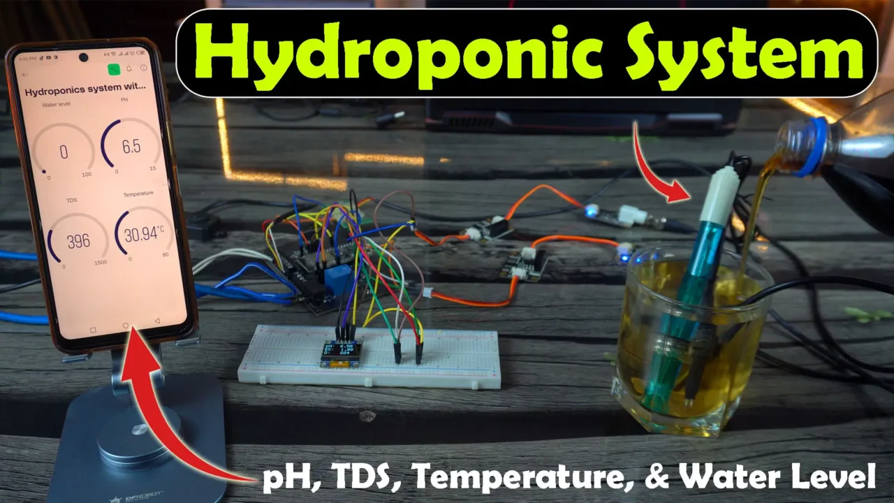
Hydroponic System using ESP32, pH Sensor, EC, DS18B20, & A02YYUW Sensor
Last Updated on August 24, 2024 by Engr. Shahzada Fahad
Table of Contents
Hydroponic System:
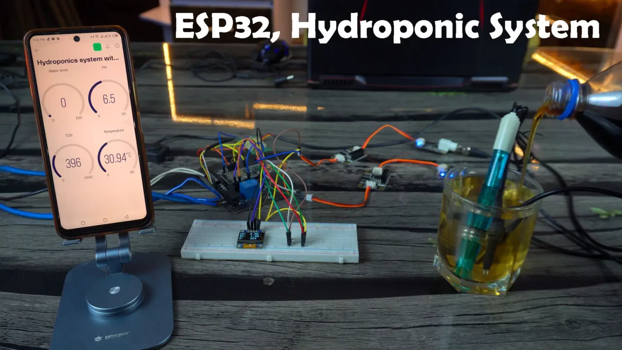
Hydroponic System using ESP32, pH Sensor, EC, DS18B20, & A02YYUW Sensor- Today, we are going to make the most practical iOT based Hydroponic System using the ESP32 WiFi + Bluetooth Module, the DFrobot’s Gravity Analog pH Sensor Kit V2, EC or TDS Sensor, Analog Signal Isolators, DS18B20 waterproofed one-wire digital temperature sensor, the most versatile UART version of the A02YYUW Waterproof Ultrasonic Sensor, and Blynk application for the monitoring.
Read our latest article on DIY Hydroponics System using pH Sensor, EC Sensor, Ultrasonic, DS18B20, & ESP32 Version 2.
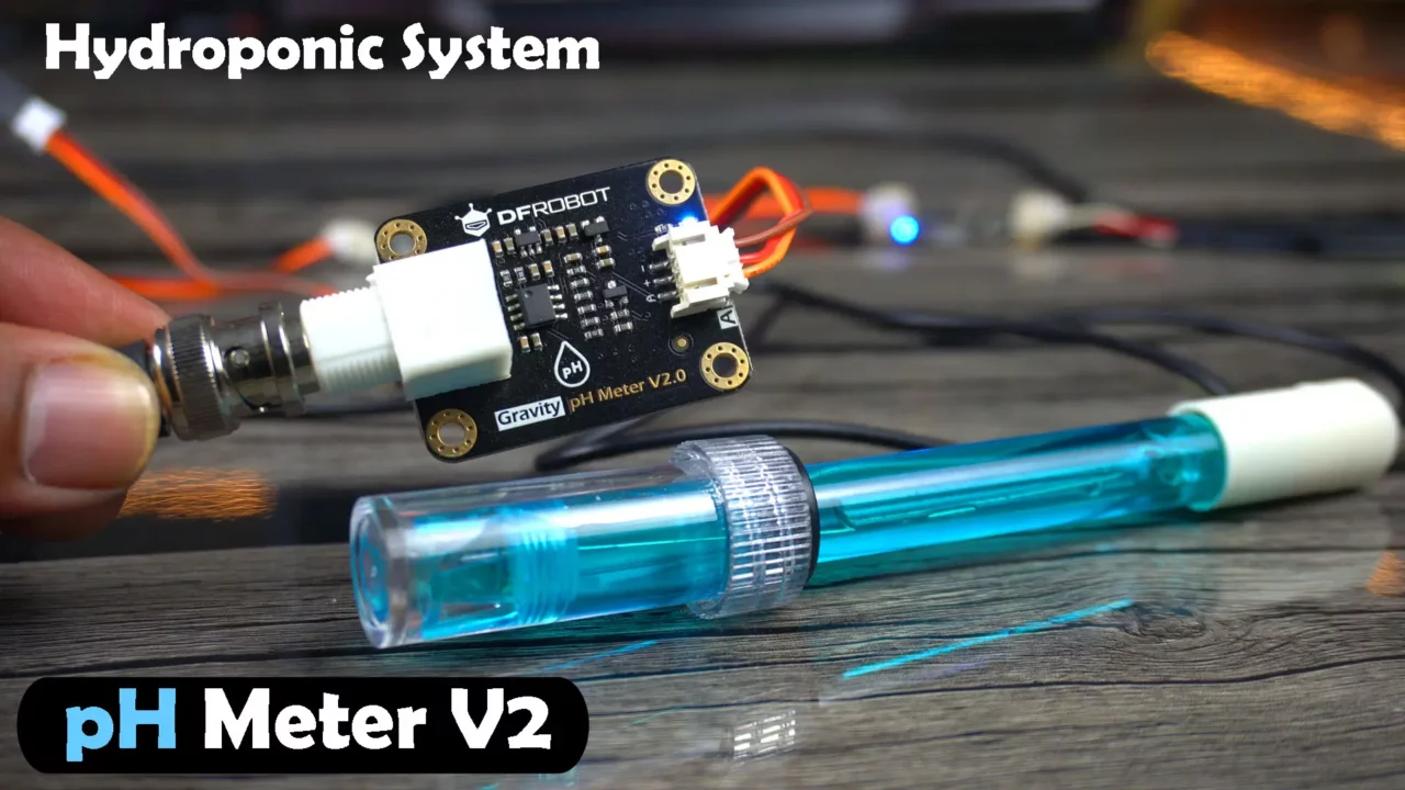
Let’s first start with the Gravity Analog pH Sensor kit V2.
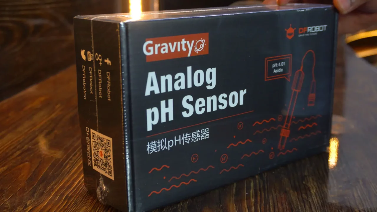
And let me also tell you this is the upgraded version of the pH meter V1 which could only be used with 5V compatible controller boards, whereas the pH Meter V2 is compatible with both 3.3V and 5V compatible controller boards.
Inside this box you get a product qualification card.
- A paper that gives you an introduction, technical details, and safety tips about pH sensor.
- A pH probe with the BNC connector.
- The pH sensor interface board or the signal conversion board. It must be kept dry and clean, otherwise, it will affect the input impedance, resulting in an inaccurate measurement.
- Some wires and screws.
- And standard buffer solutions 4.0 and 7.0. For the perfect calibration of the pH Sensor, you should have these buffer solutions. That’s why I ordered this complete kit.
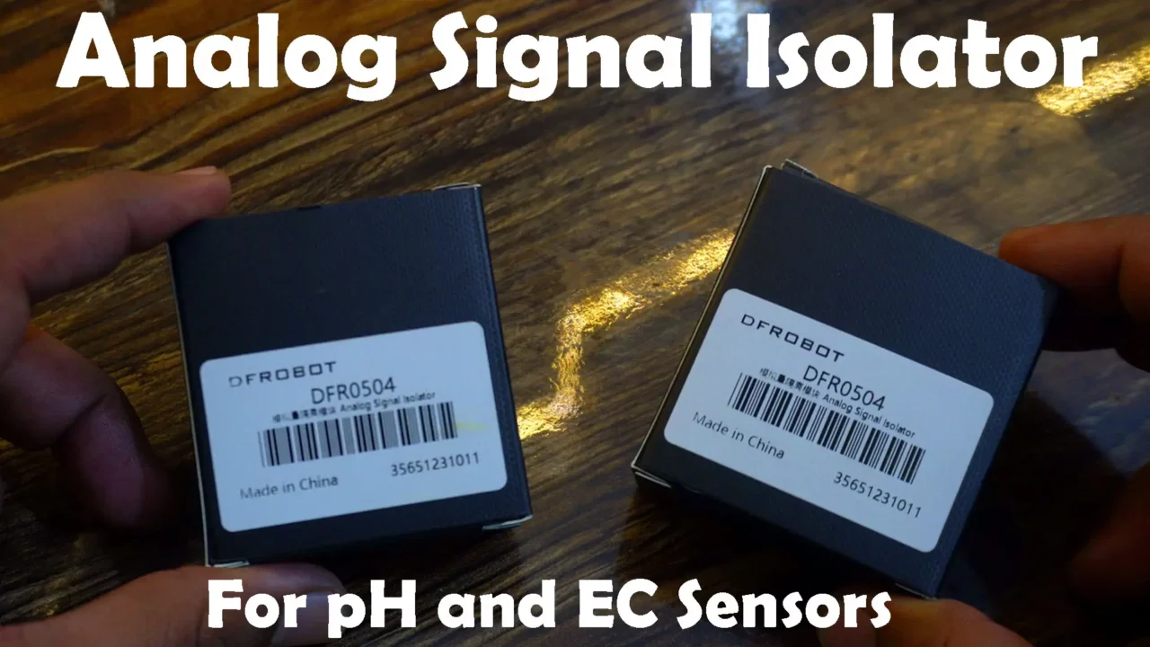
I also ordered two Analog Signal Isolators. If you have ever used a pH sensor and an EC sensor at the same time in the same container, you know that the sensor readings can get messed up because of ground looping. So, to avoid ground looping, I am going to use two Analog Signal Isolators. I will use one with the pH sensor and the other one with the EC sensor.
Besides this, I have already written getting started articles on the A02YYUW Waterproof Ultrasonic Sensor, EC Sensor, DS18B20 Waterproof One-Wire Digital Temperature Sensor, and the SSD1306 OLED Display Module.
Amazon Links:
ESP32 WiFi + Bluetooth Module (Recommended)
DS18B20 one-wire digital waterproof temperature sensor
DFrobot Gravity Analog pH sensor Kit V2
*Disclosure: These are affiliate links. As an Amazon Associate I earn from qualifying purchases.
This is a complete hydroponic system. You can directly check the water pH value, TDS or EC value, and water level in the tank on the display. You can also read these values on the Blynk app from anywhere in the world.
Right now, the pH and TDS values you see are for drinking water. Let’s add some cold drink and see if the values change.
The pH value of the water has dropped because Pepsi is acidic. So, our pH sensor and EC sensor are working well.
On the board, you can see that blue color relay, and I have connected a 110/220V AC bulb to it.
Safety:
Remember safety first, When the 110/220Vac supply is connected, never touch the relay contacts as it can be extremely dangerous. It is important to note that when working with mains voltage, proper safety precautions should always be taken and it is advisable to consult relevant electrical codes and standards.
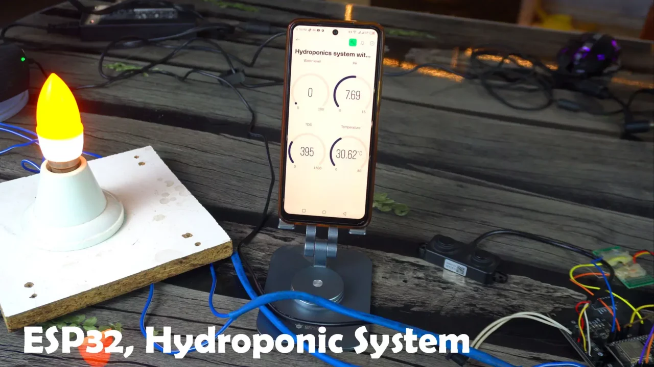
Anyway, this bulb will only turn ON when the sensor values change from the pre-set levels. For example, if the water level in the tank gets low, the bulb will turn ON; otherwise, it will stay OFF. You can do the same for pH, temperature, and TDS values based on your preference.
We can also send a notification message through the Blynk app, but as you know, the notification widget is no longer available in the free plan. So, if you want to generate notification messages, for this you will have to purchase a Pro Plan.
You might be wondering if the pH value is correct or not. Then let me tell you, I calibrated the pH sensor using buffer solutions.
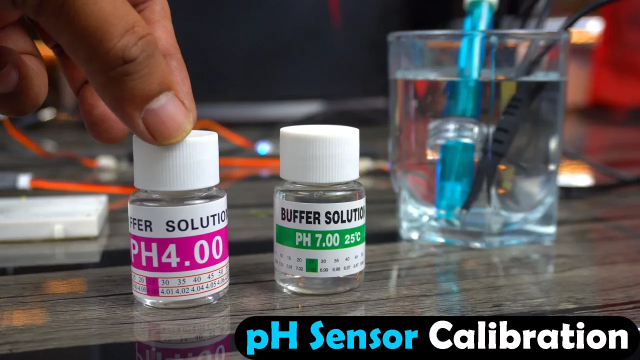
How do you know if your pH sensor is properly calibrated? Well, you need to dip the pH sensor into these buffer solutions. If you get the correct values, it means your pH sensor is calibrated correctly. Let me show it to you.
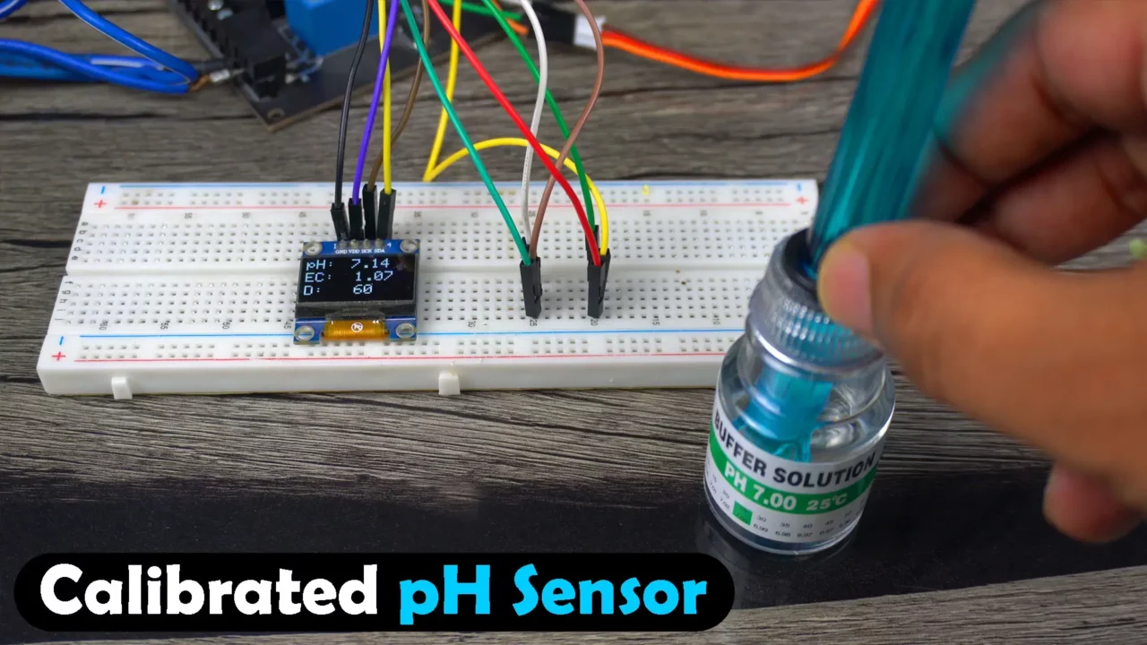
As you can see, this is the pH 7 solution. For pH 7 solution, it shows 7 on the display. A small variation is due to the temperature difference. Now, let’s test it with the pH 4 solution. Remember, when you use buffer solutions, you need to clean the probe with water each time. Make sure there isn’t any pH 7 solution on the probe when you dip it into the pH 4 solution, and vice versa.
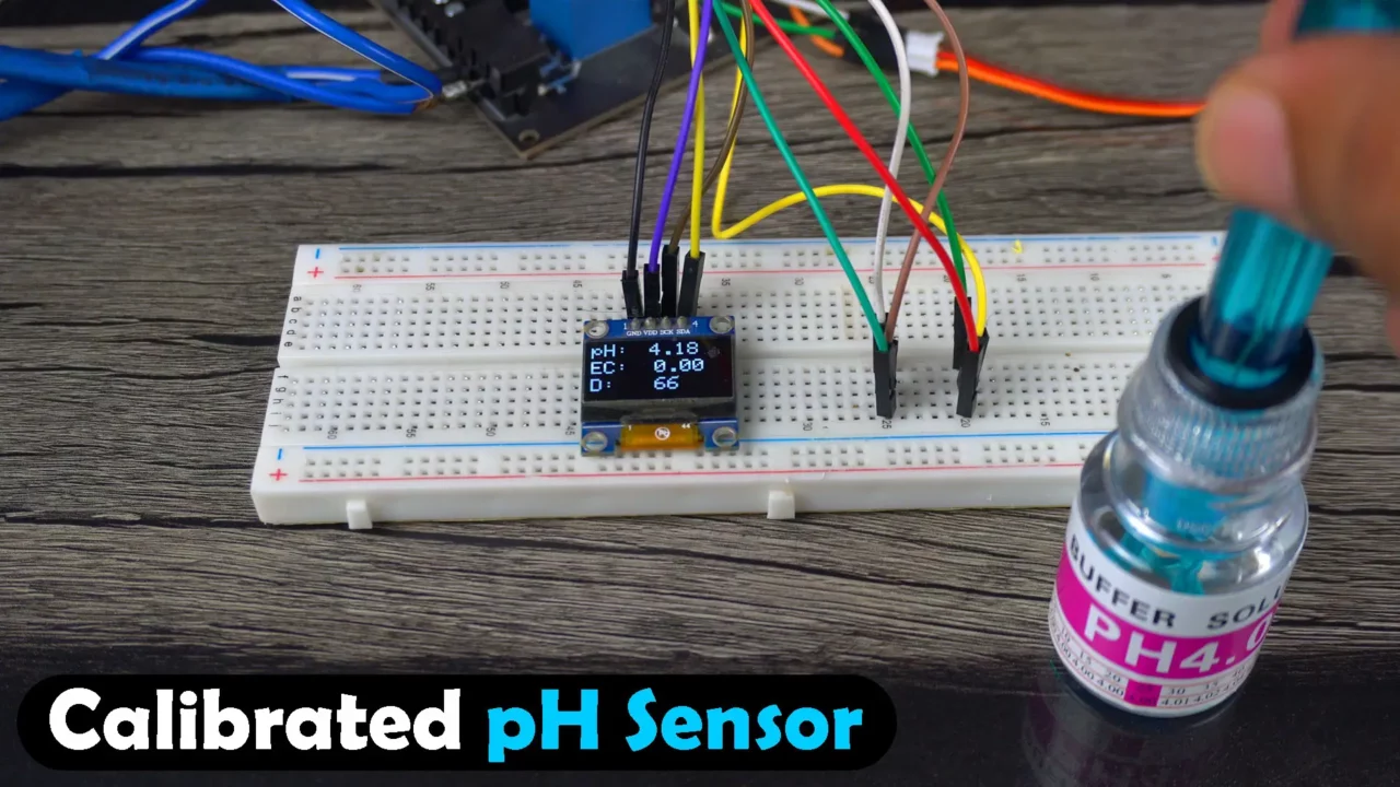
You can see that this hydroponic system successfully detected the pH 4 solution. When I used these buffer solutions for the first time, I was getting wrong pH values.
As you can see, there’s no potentiometer on the pH sensor interface board for calibration. So, I had to calibrate it by playing with the calibration value in the program, it was easy, and that’s why I recommend the DFrobot’s pH Sensors.
Anyway, during calibration, first dip the pH probe in the buffer solution. If you get the wrong value on the display, simply adjust the calibration value in the program until the pH probe reading matches the buffer solution. This process should take around 2 minutes.
Anyway, after this, when you dip the pH probe into the pH 4 solution, it will automatically detect it. If you get a wrong value, it means you didn’t calibrate it correctly.
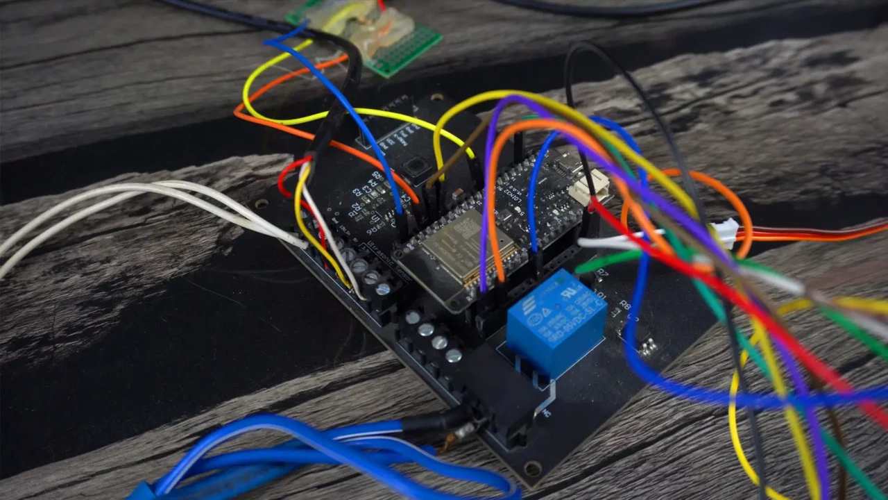
This is so far the best ESP32 Development board, and I have made many projects with it. I have even used the same board for tracking my car, I have used it with LoRa, for monitoring plants, and there are so many other projects. You can check the ESP32 Projects category.
On this board, you get a 5V and 3A power supply, which can power up many sensors and breakout boards.
Here, you can see that I have added a DC socket, so you can easily power it with any adapter from 9V to 25V. Right now I am using a 12V adapter.
Anyway, you can remove the DC socket and connect wires from a solar panel, or you can directly connect a battery. You won’t have any power-related issues with this board because I have used it a lot, and so far I have not faced any power issues.
Another good thing about this board is, you can connect a 4G LTE module. So, in places where there is no WiFi available, you can use a 4G LTE module. But for that, you will need to make some changes in the code, which I will explain in upcoming videos and articles.
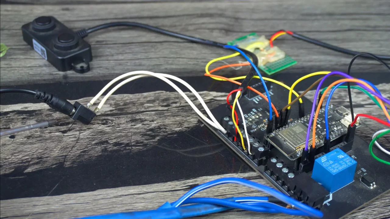
The biggest problem that people face in hydroponic systems is ground looping. I have explained this in detail in my Arduino based hydroponic system. Anyway, to solve the ground looping issue, I have used two Analog Signal Isolators, one with the EC Sensor and the other one with the pH Sensor.
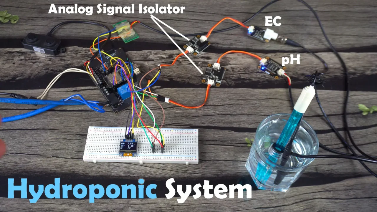
So, the final result is in front of you: the pH Sensor and TDS or EC sensor are both in the same container, and still, the values are very stable. If we didn’t use Analog Signal Isolators, we would get wrong pH and TDS values.
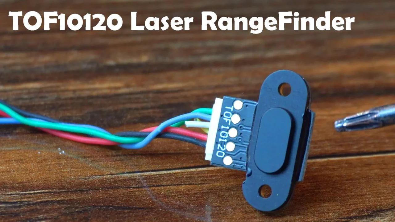
In this Hydroponic System, I could have used the TOF10120 laser Rangefinder distance sensor, which would have been quite easy for me because I have already used the TOF10120 laser distance sensor in my previous Arduino-based hydroponics system, making programming much easier for me. But I didn’t do that. Why? Because the TOF10120 laser rangefinder sensor has a very short range, and its accuracy is not good either, so using it at the product level is not good at all.
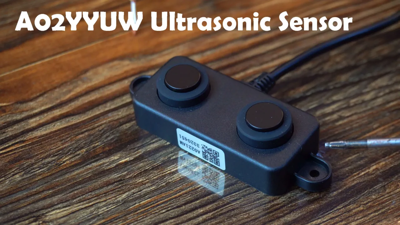
That’s why this time I used the A02YYUW waterproof ultrasonic sensor, the same sensor you will find in most high-end user products. Personally, this is my favorite distance sensor, and ever since I used it for my previous client, I have been using it in all my distance-related projects.
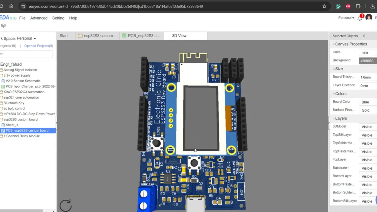
By using EasyEDA Schematic and PCB designing software, I have also designed a new Development board for the Hydroponic system. This is its first version, and it’s completely different from my other boards. On this board, I have used USB-C and ESD protection IC. This board is based on the original ESP32-S3 controller. Additionally, I have also added the SSD1306 OLED display module. Before, I further modify this board, first, I will run some tests on it, and once I am completely satisfied, then I will add a Relay and connectors for the sensors.
For this board, I have already generated the Gerber, BOM, and Pick and Place files.
Before placing an order on NextPCB, I thoroughly checked my PCB’s Gerber files using NextPCB’s HQDFM desktop software. You can also find the HQDFM service on NextPCB’s website, which you can use for free. Anyway, I also performed PCBA Analysis and DFM analysis. Any issues in your PCB design will be visible on the right side. Let’s say if I check for Signal integrity errors, you can see it has given me a complete list.
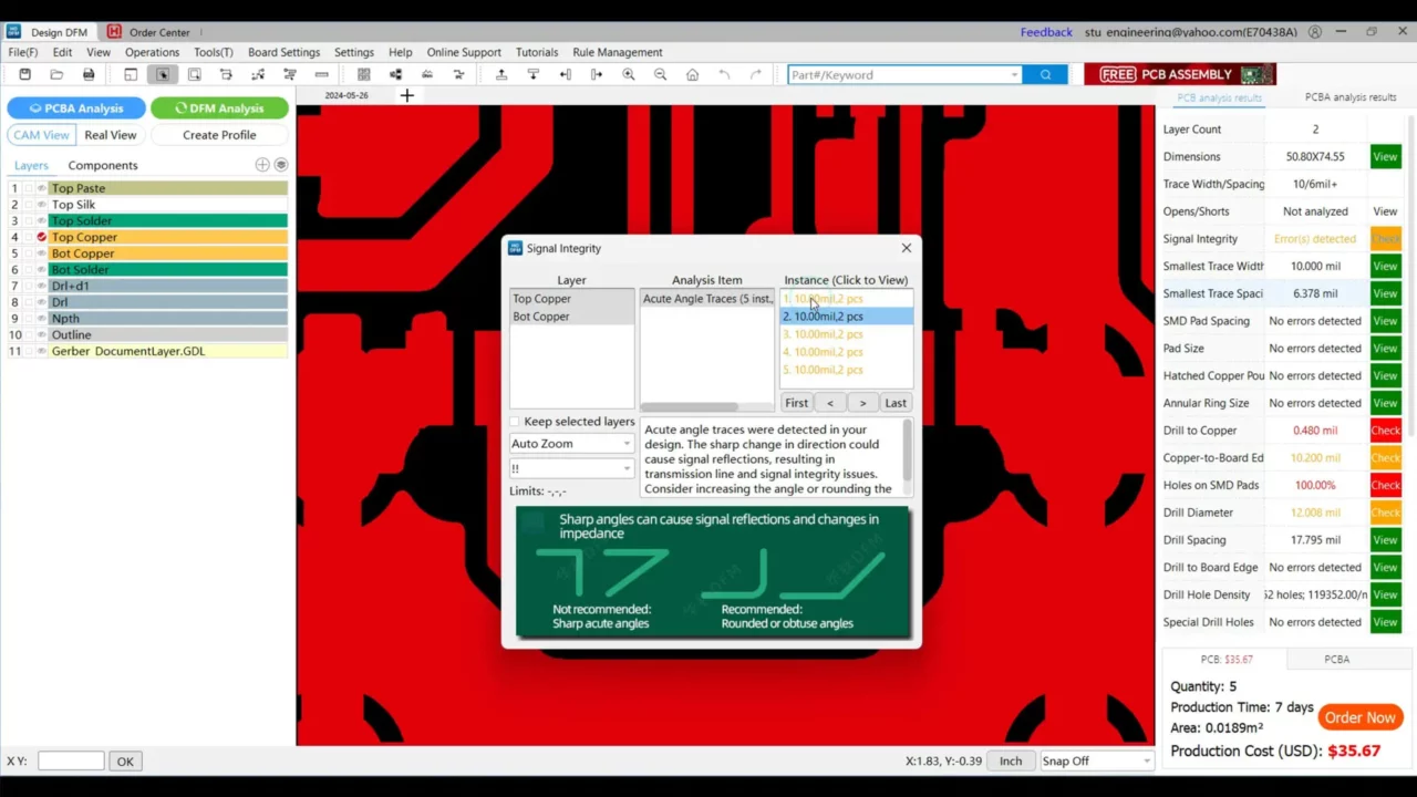
Now, I can check these errors one by one. These errors are related to acute angles; according to the design rules, PCB traces should not have sharp edges.
Anyway, after fixing the related issues, the next step is to place the PCB order. For this, you simply need to go to the NextPCB website and upload your Gerber files there. After analyzing the Gerber files for a few seconds, it will automatically detect the dimensions of the PCB. Next, you need to select the quantity; since it’s for prototyping, so, I selected 5 PCBs. After that, you can choose your favorite PCB color. If you only need PCBs, then next, you can select your shipment method, and that’s it. Your order will be placed.
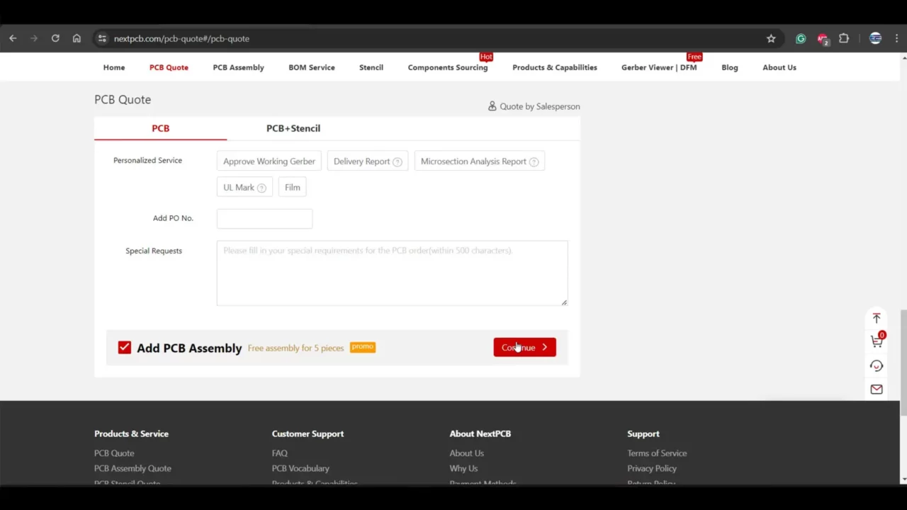
But if you also need PCB assembly services, you need to check the “Add PCB Assembly” box, and then go ahead and click on the continue button.
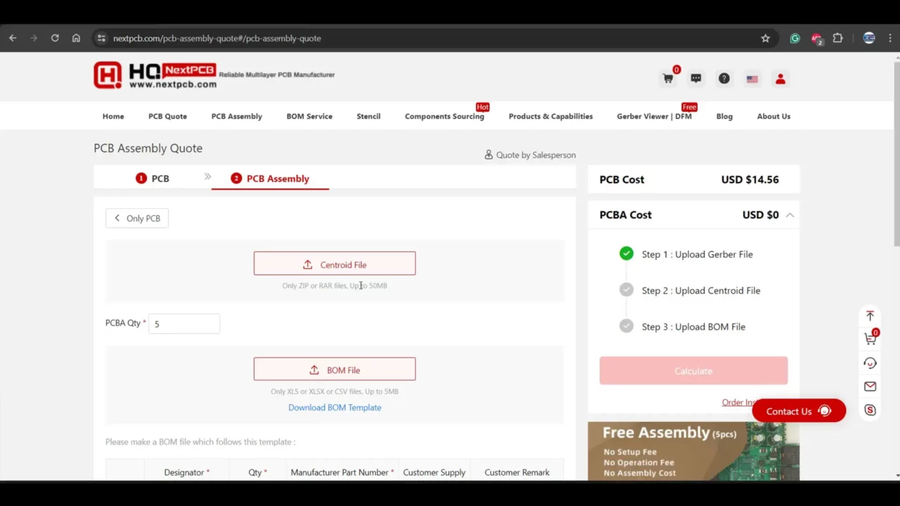
Next, for PCB assembly, you also need to add the Centroid file, which is a pick and place file. You can generate this file in EasyEDA software with just a single button click.
You will also need to add the BOM file, which you can also generate in EasyEDA. While designing the PCB, try to use parts that are available in stock. It’s going to take some time to analyze the BOM File.
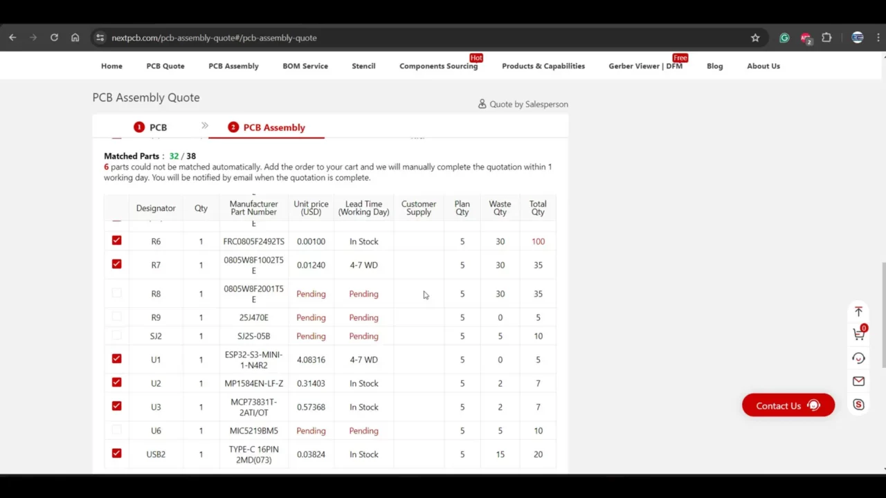
You can see they don’t have some parts available, but don’t worry because NextPCB also provides component sourcing services. So, they will arrange the missing parts themselves. But for confirmation, they will send you an email, and you will need to answer yes or no. So, you don’t need to search for components. Let the NextPCB engineers do it for you.
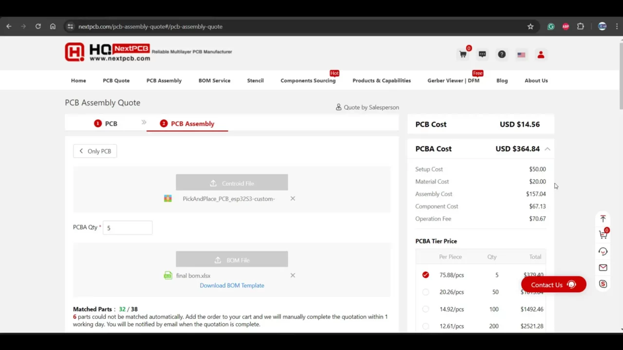
Right now, you can see the assembly cost is quite high, and that’s because we are only ordering 5 PCBs. When the quantity of PCBs is higher, the cost decreases significantly. And I have a Pro tip for you.
For 5 PCBs, you can use their assembly services for free if the quantity of components on your board is 30 or less. So, for prototyping, try to limit your BOM file to 30 components, and delete the remaining components. Don’t delete components that are difficult to solder or hard to find. In my case, I placed a full order because I don’t have most of the components. So, I want NextPCB to arrange and solder those components for me.
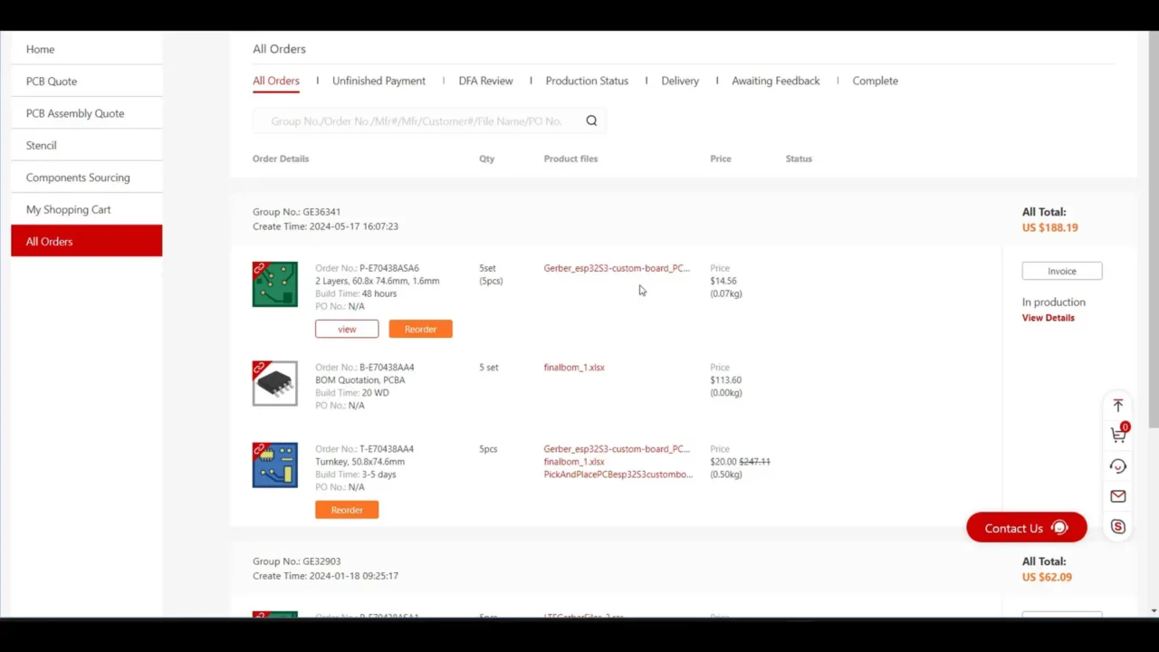
I have placed this dummy order for you. You can see the cost of PCBs is 14.56USD, the cost of components for 5 PCBs is 113.6USD, which is great. And the PCB assembly cost is only 20USD. The actual price was 247USD.
So, if you also want to reduce the cost of your prototype PCBs, you can do the same as I suggested. Anyway, I have already placed my order, and as soon as I receive the PCBs, I will share updates with you.
By the way, the PCB board I am currently using, I have also manufactured it from NextPCB. Their PCB quality is quite amazing. What are you waiting for, click on the PCB Quote and order yourself high-quality PCBs.
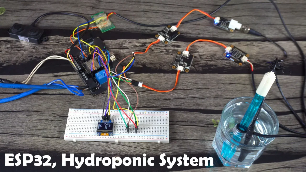
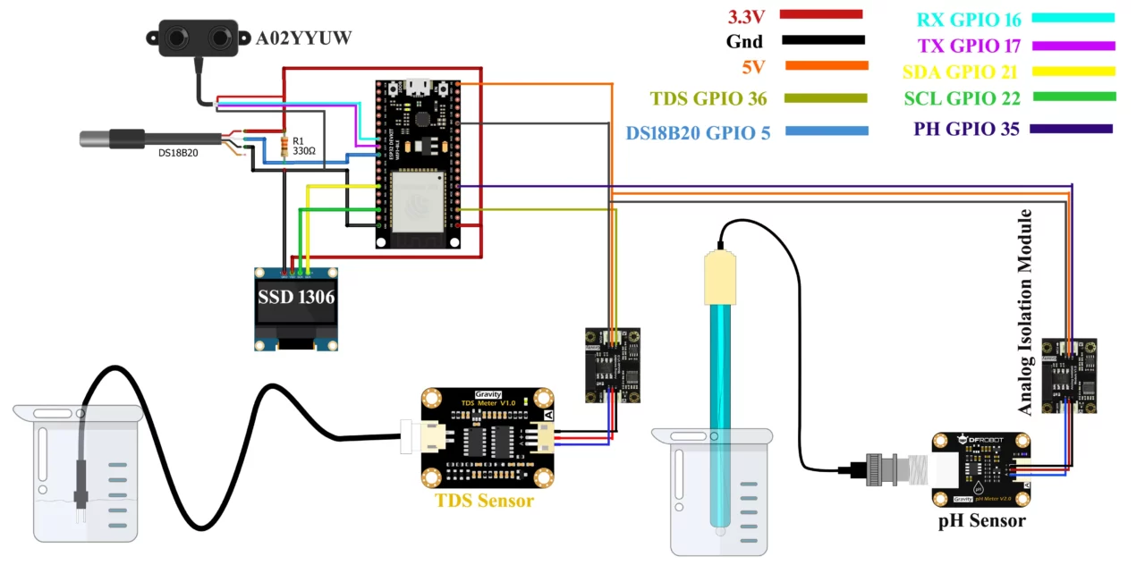
Anyway, if you don’t have a development board, you can also do the same exact connections on a breadboard. For connections, you can follow this circuit diagram.
Now, let’s start with the Blynk Web Dashboard setup.
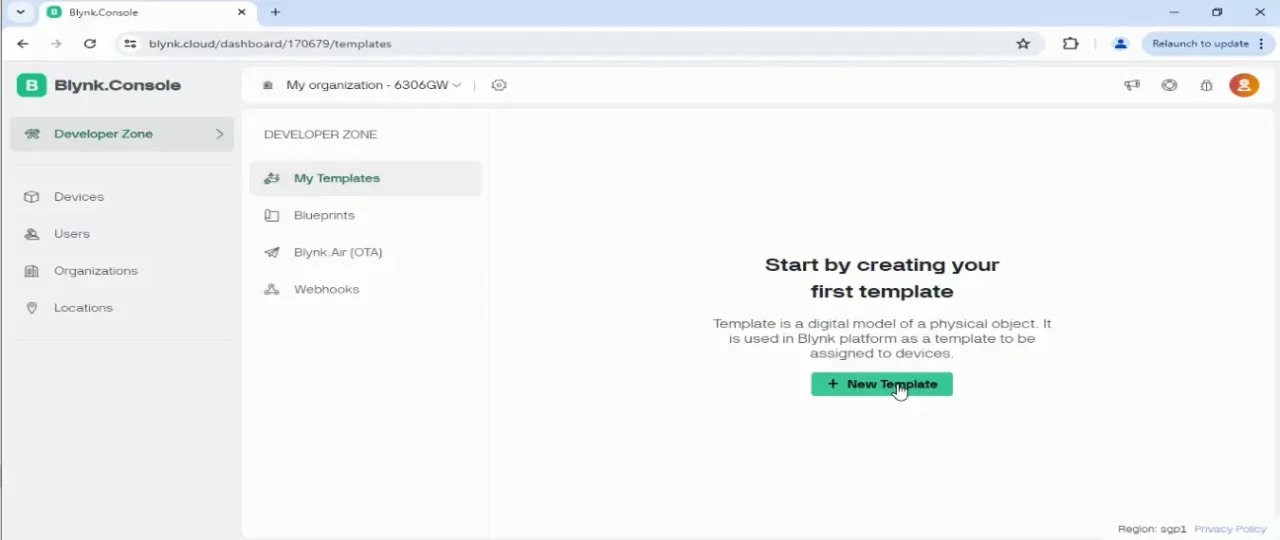
Blynk Web Dashboard Setup:
While you are logged-in into your Blynk account.
Click on the New Template.
Write the Template Name.
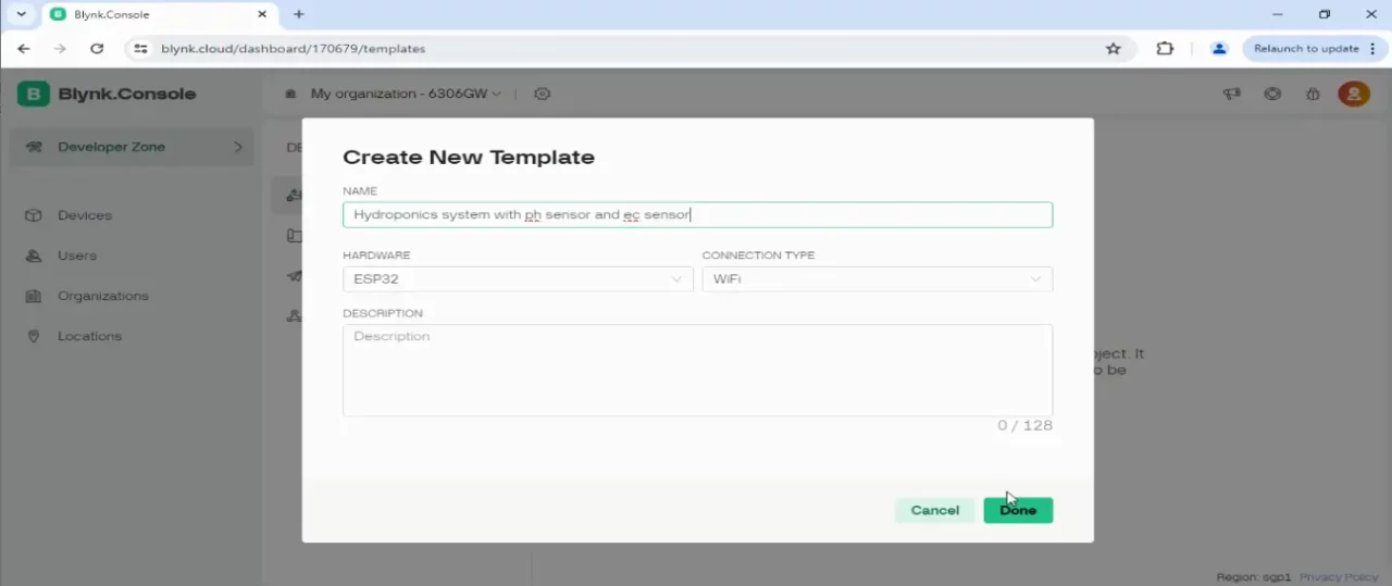
While ESP32 is selected as the Hardware type and WiFi as the connection type; click on the Done button.
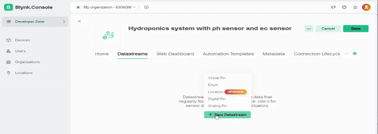
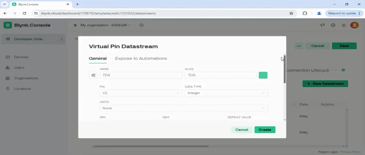
While you are on the Datastreams tab, click on the + New Datastream and select Virtual Pin.
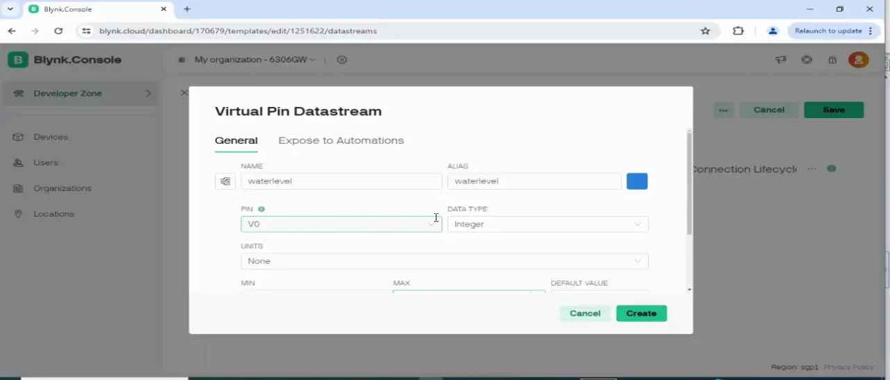
On the Virtual Pin Datastream, select the virtual pin V0, then the type as interger, and define the min and max values. On this virtual pin we will monitor the water level percentage. So, that’s why I selected the min value as 0 and the maximum value of 100. Finally, click on the Create button.
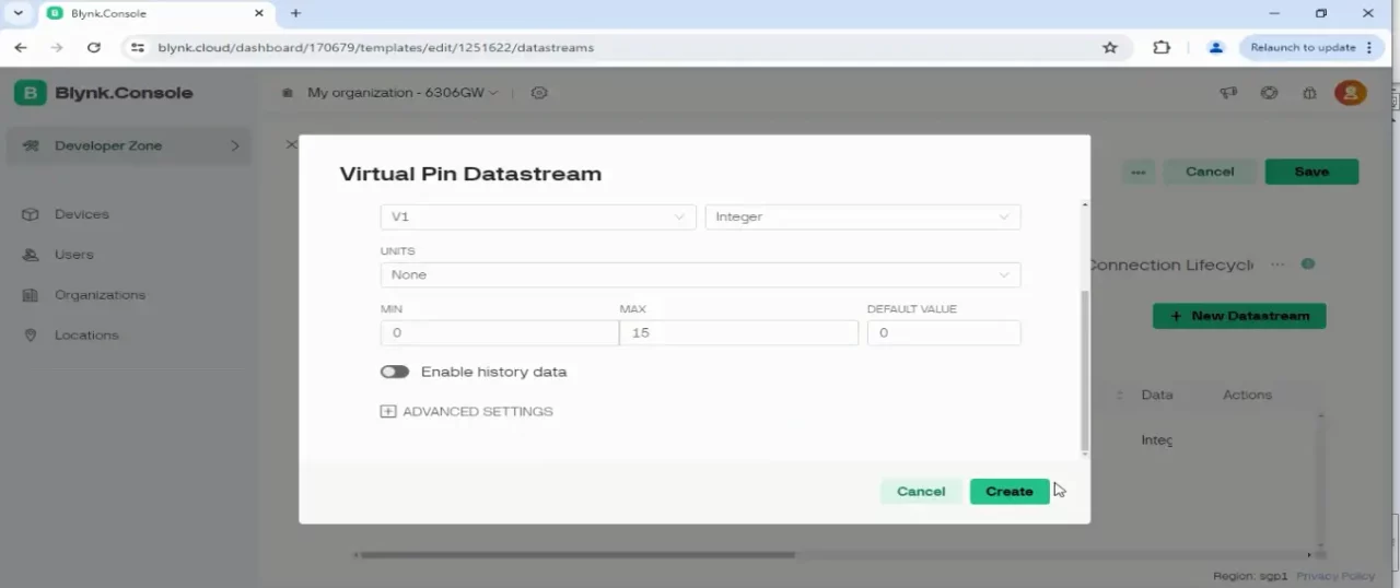
Follow the same exact steps and create thre more virtual pins (V1, V2, and V3) and select the MIN and MAX values accordingly. We are going to use the Virtual pin V1 for monitoring the water pH value; and you know the pH value is between 0 and 14. So, you can set the Min value as 0 and MAX value to 14. Select the data type as float.
Following the same method, create another virtual pin V2 for monitoring the TDS value.
If you face any issues then you can follow the video tutorial available at the end of this article.
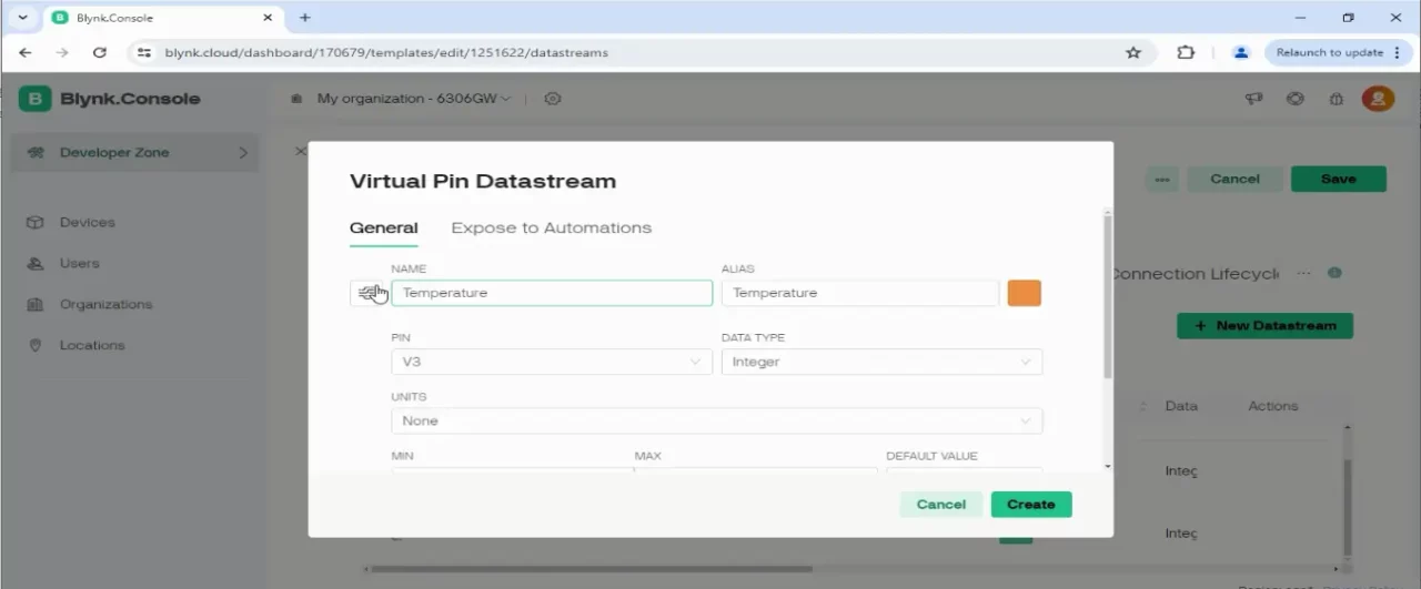
Following the same method, create another virtual pin V3 for monitoring the Temperature value. Select the data type as float; select the MIN and MAX values.
Anyway, once all the four datastreams are defined. Then you can go to the Web Dashboard tab and start adding widgets to your dashboard.
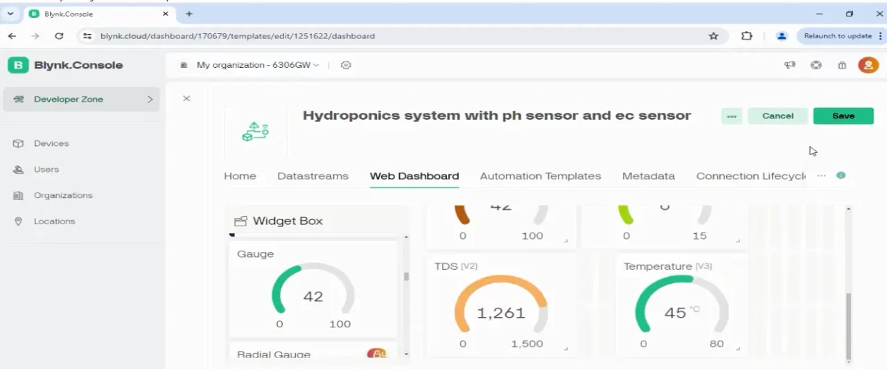
You can clearly see, I have added Gauges for the water level monitoring, pH Sensor, TDS Sensor, and Temperature Sensor. I assigned the virtual pin V0 to the Water level, Virtual pin V1 to the pH Sensor, Virtual pin V2 to the TDS, and Virtual pin V3 to the Temperature.
Let me remind you one more time, if you face any issues, you can watch my video tutorial.
Next, on the Left side you can see Devices, buddy you need to click on it.
Now, on the right side, you will see the + New Device, click on it to add your device.
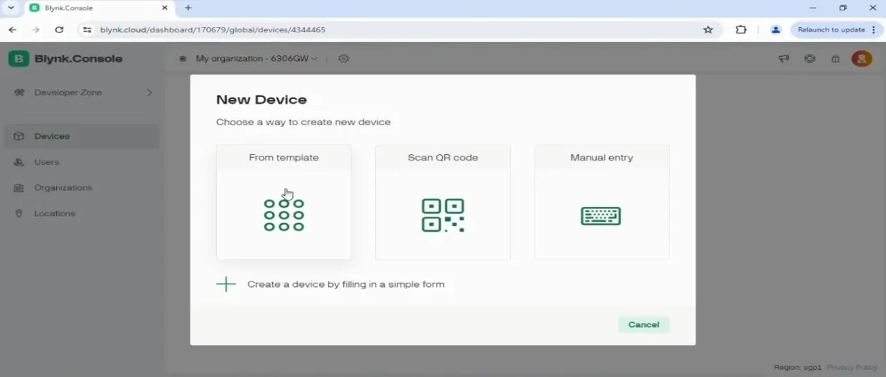
Choose a way to create new device. We are going to select From Template.
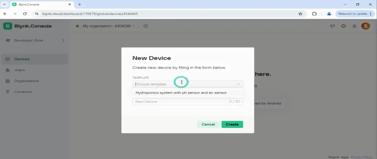
Click on the Choose template and select your template that is “Hydroponics system with ph sensor and ec sensor”.
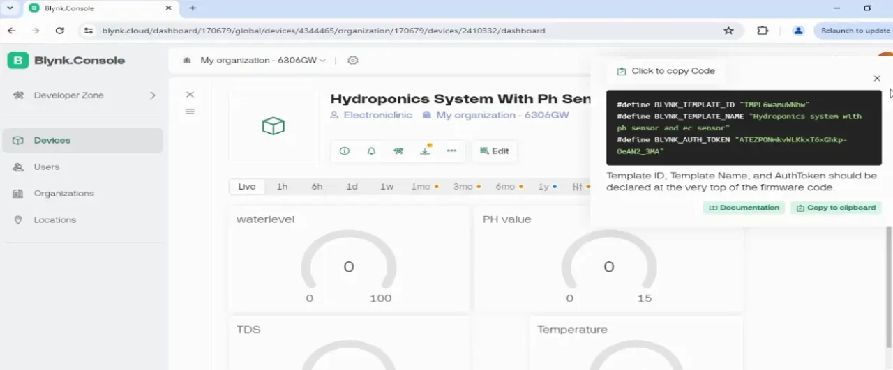
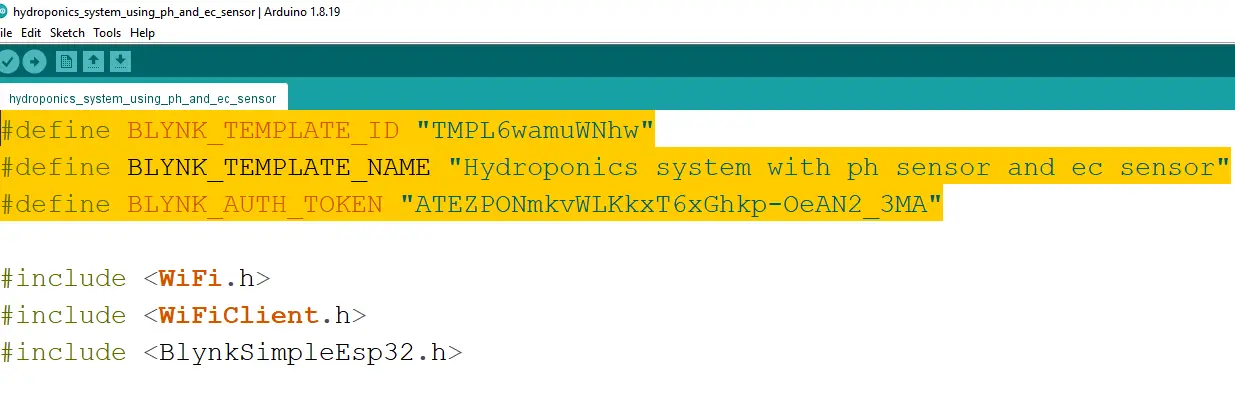
When the dashboard is ready, simply copy these credentials, open the program given below, and paste the credentials.
Don’t forget to change the GPRS Credentials.
Hydroponic ESP32 Programming:
|
1 2 3 4 5 6 7 8 9 10 11 12 13 14 15 16 17 18 19 20 21 22 23 24 25 26 27 28 29 30 31 32 33 34 35 36 37 38 39 40 41 42 43 44 45 46 47 48 49 50 51 52 53 54 55 56 57 58 59 60 61 62 63 64 65 66 67 68 69 70 71 72 73 74 75 76 77 78 79 80 81 82 83 84 85 86 87 88 89 90 91 92 93 94 95 96 97 98 99 100 101 102 103 104 105 106 107 108 109 110 111 112 113 114 115 116 117 118 119 120 121 122 123 124 125 126 127 128 129 130 131 132 133 134 135 136 137 138 139 140 141 142 143 144 145 146 147 148 149 150 151 152 153 154 155 156 157 158 159 160 161 162 163 164 165 166 167 168 169 170 171 172 173 174 175 176 177 178 179 180 181 182 183 184 185 186 187 188 189 190 191 192 193 194 195 196 197 198 199 200 201 202 203 204 205 206 207 208 209 210 211 212 213 214 215 216 217 218 219 220 221 222 223 224 225 226 227 228 229 230 231 232 233 234 235 236 237 238 239 240 241 242 243 244 245 246 247 248 249 250 251 252 253 254 255 256 257 258 259 260 261 262 263 |
/* * https://www.electroniclinic.com/ * Hydroponic System by Engr. Fahad */ #define BLYNK_TEMPLATE_ID "TMPL6wamuWNhw" #define BLYNK_TEMPLATE_NAME "Hydroponics system with ph sensor and ec sensor" #define BLYNK_AUTH_TOKEN "ATEZPONmkvWLKkxT6xGhkp-OeAN2_3MA" #include <WiFi.h> #include <WiFiClient.h> #include <BlynkSimpleEsp32.h> #include <OneWire.h> #include <Wire.h> #include <DallasTemperature.h> #include <Adafruit_GFX.h> #include <Adafruit_SSD1306.h> #include <SimpleTimer.h> #include <HardwareSerial.h> char auth[] = BLYNK_AUTH_TOKEN; // Your WiFi credentials. // Set password to "" for open networks. char ssid[] = "AndroidAP3DEC"; char pass[] = "electroniclinic"; // distance sensor start HardwareSerial Ultrasonic_Sensor(2); // TX2 (pin 17), RX2 (pin 16) // Define connections to sensor int pinRX = 16; // Choose a suitable pin for RX int pinTX = 17; // Choose a suitable pin for TX // Array to store incoming serial data unsigned char data_buffer[4] = {0}; int distance; // Variable to hold checksum unsigned char CS; int Relay = 13; int Relay_Status = 0; int waterLevelPer=0; int Percentage = 0; int previousDistance; unsigned long distanceChangeTime; //end distance sensor SimpleTimer timer; SimpleTimer timer1; float calibration_value = 15.65 - 0.7; int phval = 0; unsigned long int avgval; int buffer_arr[10],temp; float ph_act; #define SCREEN_WIDTH 128 // OLED display width, in pixels #define SCREEN_HEIGHT 64 // OLED display height, in pixels // Declaration for an SSD1306 display connected to I2C (SDA, SCL pins) #define OLED_RESET -1 // Reset pin # (or -1 if sharing Arduino reset pin) Adafruit_SSD1306 display(SCREEN_WIDTH, SCREEN_HEIGHT, &Wire, OLED_RESET); namespace pin { const byte tds_sensor = A0; // 36 const byte one_wire_bus = 5; // Dallas Temperature Sensor } namespace device { float aref = 3.3; // Vref, this is for 3.3v compatible controller boards, for arduino use 5.0v. } namespace sensor { float ec = 0; unsigned int tds = 0; float waterTemp = 0; float ecCalibration = 1; } OneWire oneWire(pin::one_wire_bus); DallasTemperature dallasTemperature(&oneWire); void setup() { Serial.begin(115200); // Dubugging on hardware Serial 0 Ultrasonic_Sensor.begin(9600, SERIAL_8N1, pinRX, pinTX); // Initialize the hardware serial dallasTemperature.begin(); Blynk.begin(auth, ssid, pass); display.begin(SSD1306_SWITCHCAPVCC, 0x3C); delay(2000); display.clearDisplay(); display.setTextColor(WHITE); pinMode(Relay,OUTPUT); digitalWrite(Relay,LOW); timer.setInterval(1000L, display_pHValue); timer1.setInterval(5000L, EC_and_ph); } void loop() { Blynk.begin(); timer.run(); // Initiates SimpleTimer timer1.run(); A02YYUW_Sensor(); } void readTdsQuick() { dallasTemperature.requestTemperatures(); sensor::waterTemp = dallasTemperature.getTempCByIndex(0); float rawEc = analogRead(pin::tds_sensor) * device::aref / 4096; // read the analog value more stable by the median filtering algorithm, and convert to voltage value float temperatureCoefficient = 1.0 + 0.02 * (sensor::waterTemp - 25.0); // temperature compensation formula: fFinalResult(25^C) = fFinalResult(current)/(1.0+0.02*(fTP-25.0)); sensor::ec = (rawEc / temperatureCoefficient) * sensor::ecCalibration; // temperature and calibration compensation sensor::tds = (133.42 * pow(sensor::ec, 3) - 255.86 * sensor::ec * sensor::ec + 857.39 * sensor::ec) * 0.5; //convert voltage value to tds value Serial.print(F("TDS:")); Serial.println(sensor::tds); Serial.print(F("EC:")); Serial.println(sensor::ec, 2); Serial.print(F("Temperature:")); Serial.println(sensor::waterTemp,2); } void ph_Sensor() { for(int i=0;i<10;i++) { buffer_arr[i]=analogRead(35); delay(30); } for(int i=0;i<9;i++) { for(int j=i+1;j<10;j++) { if(buffer_arr[i]>buffer_arr[j]) { temp=buffer_arr[i]; buffer_arr[i]=buffer_arr[j]; buffer_arr[j]=temp; } } } avgval=0; for(int i=2;i<8;i++) avgval+=buffer_arr[i]; float volt=(float)avgval*3.3/4096.0/6; //Serial.print("Voltage: "); //Serial.println(volt); ph_act = -5.70 * volt + calibration_value; Serial.print("pH Val: "); Serial.println(ph_act); // delay(1000); } void display_pHValue() { // display on Oled display // Oled display display.clearDisplay(); display.setTextSize(2); display.setCursor(0,0); // column row display.print("pH:"); display.setTextSize(2); display.setCursor(55, 0); display.print(ph_act); display.setTextSize(2); display.setCursor(0,20); display.print("EC:"); display.setTextSize(2); display.setCursor(60, 20); display.print(sensor::ec); display.setTextSize(2); display.setCursor(0,40); display.print("D:"); display.setTextSize(2); display.setCursor(60, 40); display.print(distance); display.display(); Blynk.virtualWrite(V0, waterLevelPer); Blynk.virtualWrite(V1, ph_act); Blynk.virtualWrite(V2, sensor::tds); Blynk.virtualWrite(V3, sensor::waterTemp); } void A02YYUW_Sensor() { // Run if data available if (Ultrasonic_Sensor.available() > 0) { delay(4); // Check for packet header character 0xff if (Ultrasonic_Sensor.read() == 0xff) { // Insert header into array data_buffer[0] = 0xff; // Read remaining 3 characters of data and insert into array for (int i = 1; i < 4; i++) { data_buffer[i] = Ultrasonic_Sensor.read(); } //Compute checksum CS = data_buffer[0] + data_buffer[1] + data_buffer[2]; // If checksum is valid compose distance from data if (data_buffer[3] == CS) { distance = (data_buffer[1] << 8) + data_buffer[2]; // Print to serial monitor distance= distance / 10; // cm if (distance >= 80) { digitalWrite(Relay, HIGH); delay(10); } if (distance <= 10 ) { digitalWrite(Relay, LOW); delay(10); } } } } Serial.print("distance: "); Serial.print(distance); Serial.println(" cm"); waterLevelPer = map(distance, 26, 73, 100, 0); delay(10); } void EC_and_ph() { readTdsQuick(); // delay(20); ph_Sensor(); // delay(20); } |
If this is your first time using the ESP32 WiFi + Bluetooth module then you will also need to install the ESP32 board in the Arduino IDE.
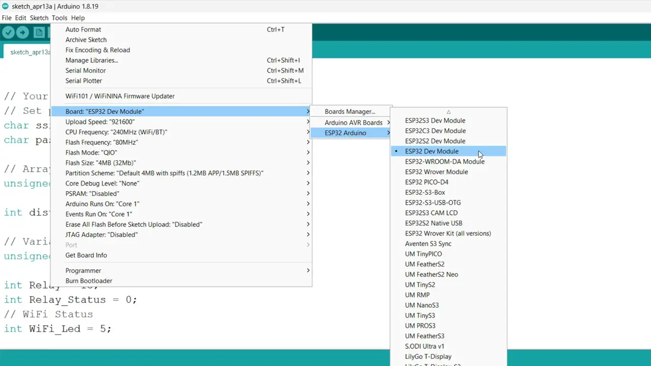
For this you can read my getting started article on the ESP32 WiFi + Bluetooth Module.
Next, you will also need to install the entire blynk library package. For this simply go to the Sketch Menu, then to Include Library, and click on the Manage Libraries.
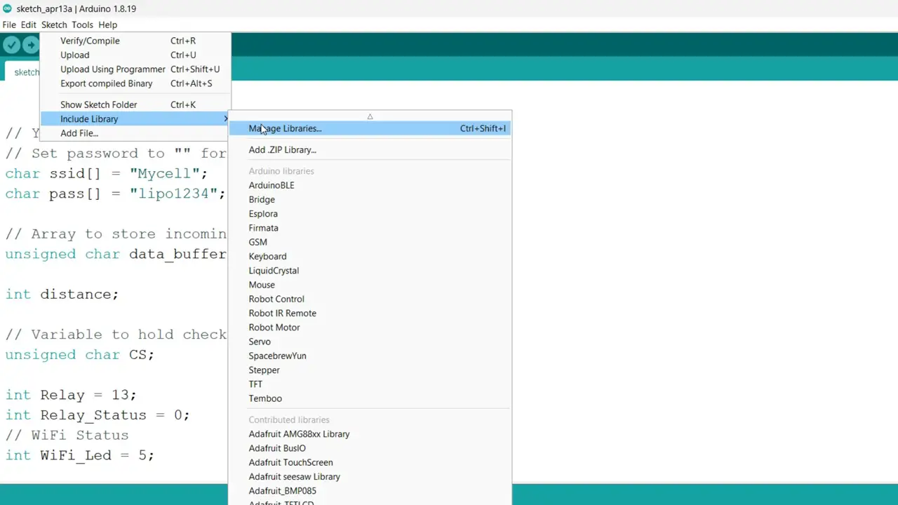
Type Blynk in the search box.
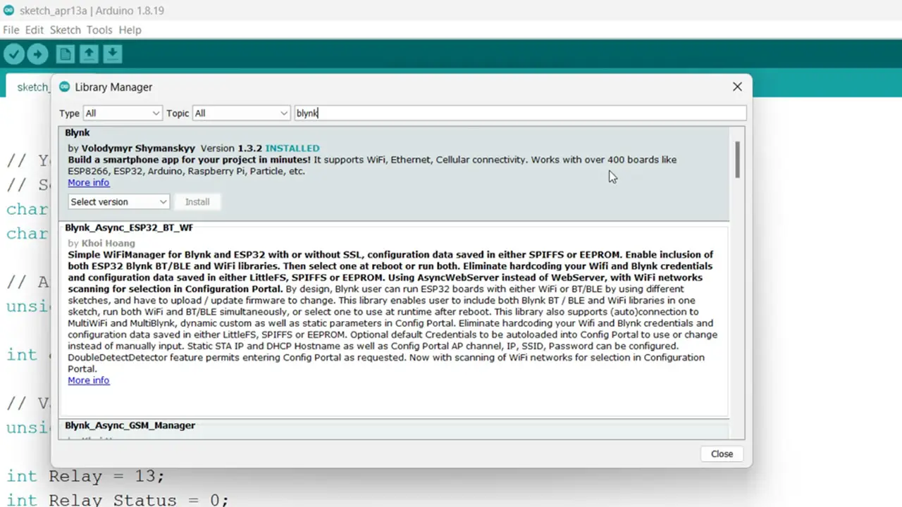
You can see I have also installed this library. It works with over 400 boards.
Repeat the same exact steps for all the remaining libraries. If you face any issues then you can watch my video tutorial given at the end of this article.
Finally, you can upload the program. In my case, I have already uploaded this program. Next, you can start with the Blynk IoT Application setup on your Smartphone.
Blynk IoT App setup on Smartphone:
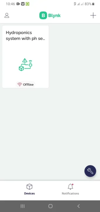
For this, first of all, you will need to install the IoT blynk in your smart phone. Make sure; you log in with the same email that you used on your computer. Simply, open your Blynk application on your cell phone and select your project.
After this, things are pretty straightforward, you need to add 4 gauges and assign them the desired Datastreams. You don’t need to create the Datastreams, we already did it.
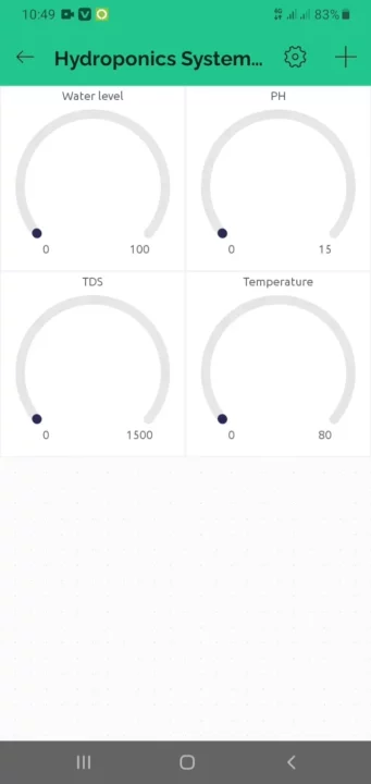
I assigned the Datastream V0 to the Water Level widget, V1 to the pH Sensor Widget, V2 to the TDS widget, and V3 to the Temperature.
If you face any issues then you can watch my video tutorial given below.
Watch Video Tutorial:

Discover more from Electronic Clinic
Subscribe to get the latest posts sent to your email.


Boa tarde! Como você esta? Gostei muito do seu projeto, está de parabéns! Teria como me enviar o desenho da placa da placa para fazer uma para min?