TDS Sensor or EC Sensor with ESP8266 for Water Quality Monitoring
IoT Water Quality Monitoring using ESP8266 & TDS or EC Sensor
Last Updated on September 21, 2024 by Engr. Shahzada Fahad
Table of Contents
TDS Sensor or EC Sensor with ESP8266:
TDS Sensor or EC Sensor with ESP8266 for Water Quality Monitoring– I have written several articles on the DFRobot TDS Sensor or EC Sensor or Electrical Conductivity Sensor. I have used it with Arduino for water quality monitoring and I explained in detail what is TDS or total dissolved solids and I also explained what is EC or Electrical Conductivity, and how to calculate the TDS and EC values.
I have also used the same TDS or EC sensor along with a pH sensor and DS18B20 Waterproof digital temperature sensor for building a Hydroponics system.
I have also used the same TDS sensor in an IoT based water quality monitoring system using ESP32 WiFi + Bluetooth module and the Blynk application.
Now, you might be thinking, if I have already used this sensor in some basic and advanced-level projects then why am I making this video? Well there are some reasons
- I have never used this TDS sensor with ESP8266. And moreover, lots of guys have been asking me if they can use this sensor with the Nodemcu ESP8266 instead of using ESP32. So, today I will be using Nodemcu ESP8266 WiFi module.
- The 2nd reason I am writing this article is that the older version of the Blynk or Blynk legacy is now closed for new user registrations and it’s going to be completely shutdown on December 31, 2022 and you will no longer be able to use the older version of the Blynk application. So, this time, I will be using the new Blynk 2.0. If you are a beginner and you have never used the Blynk application then I highly recommend you should read my getting started article on the new Blynk 2.0.
- Previously, I used 16×2 LCD while this time I will be using an I2C supported SSD1306 Oled display Module.
Anyway, after reading this article, you will be able to use your EC or TDS sensor with the Nodemcu ESP8266 WiFi module along with the DS18b20 waterproof temperature sensor and the new Blynk V2.0.

Here is my prototype model. I have connected the TDS Sensor, SSD1306 Oled display Module, and DS18b20 temperature sensoras per the circuit diagram which I will explain in a minute.Anyway, let’s go ahead and kick off our practical demonstration, and afterward I will explain everything else.

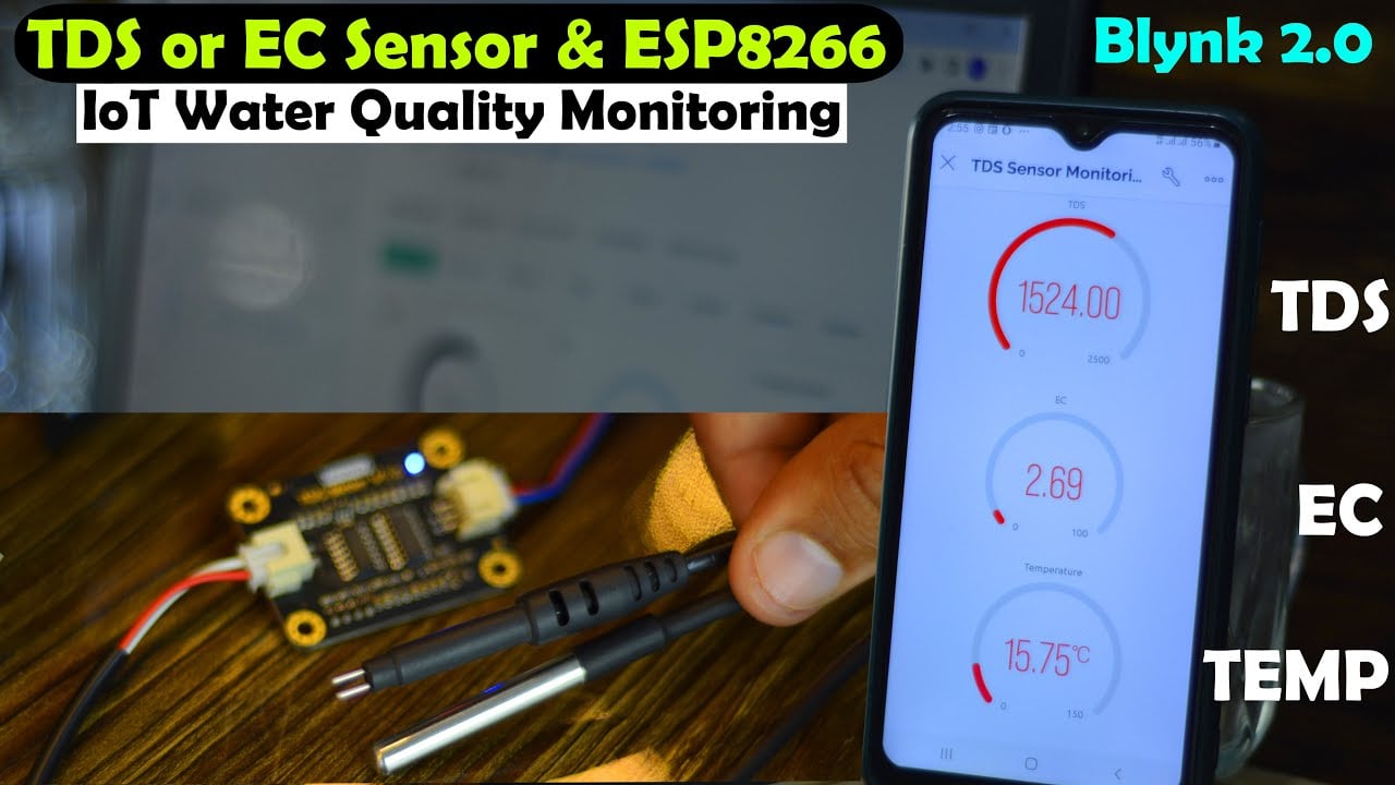
Right now the Nodemcu ESP8266, my cell phone, and the laptop all are connected to WiFi. It entirely depends on you if you choose to use the same WiFi network or different WiFi networks. Anyway right now, you can see the TDS, EC, and Temperature values on the Oled display module, and also on the Blynk IoT Mobile Application and Blynk.cloud Dashboard. These are the values when the TDS sensor and DS18b20 Temperature sensors are not submerged in water.

These are the values of the TDS, EC, and Temperature values when I dipped the TDS sensor and DS18B20 temperature sensor in the drinking water. Next, I added some salt in the water.

After adding salt in the water, the TDS and EC values increased. I don’t know if you guys can clearly see the values. For the practical demonstration you can watch the video tutorial available on my YouTube channel Electronic Clinic. I am sure by now, you might have got an idea of how does this system work. So, without any further delay let’s get started!!!
Amazon Links:
DS18B20 waterproof temperature sensor
Disclosure: These are affiliate links. As an Amazon Associate I earn from qualifying purchases.
TDS sensor:
Gravity: Analog TDS Sensor/Meter is compatible with 5V and 3.3V controller boards like Arduino, ESP8266, ESP32, STM32, ETC.This TDS Meter Kit is used for measuring TDS value of the water, to reflect the cleanliness of the water. TDS meter can be applied to domestic water, hydroponic and other fields of water quality testing.
TDS (Total Dissolved Solids) indicates that how many milligrams of soluble solids dissolved in one liter of water. In general, the higher the TDS value, the more soluble solids dissolved in water, and the less clean the water is. Therefore, the TDS value can be used as one of the references for reflecting the cleanliness of water.

FEATURES
- Wide Voltage Input: 3.3~5.5V
- Good Compatibility Output: 0~2.3V analog signal output, compatible with 5V or 3.3V controller
- AC Excitation Source: effectively prevent the probe from polarization
- Waterproof Probe
- Easy to Use: Arduino compatible, simple connection, plug, and play without soldering
SPECIFICATION
Signal Transmitter Board
- Input Voltage: 3.3 ~ 5.5V
- Output Voltage: 0 ~ 2.3V
- Working Current: 3 ~ 6mA
- TDS Measurement Range: 0 ~ 1000ppm
- TDS Measurement Accuracy: ± 10% F.S. (25 ℃)
- Module Size: 42 * 32mm
- Module Interface: PH2.0-3P
- Electrode Interface: XH2.54-2P
TDS Sensor interfacing with ESP8266:
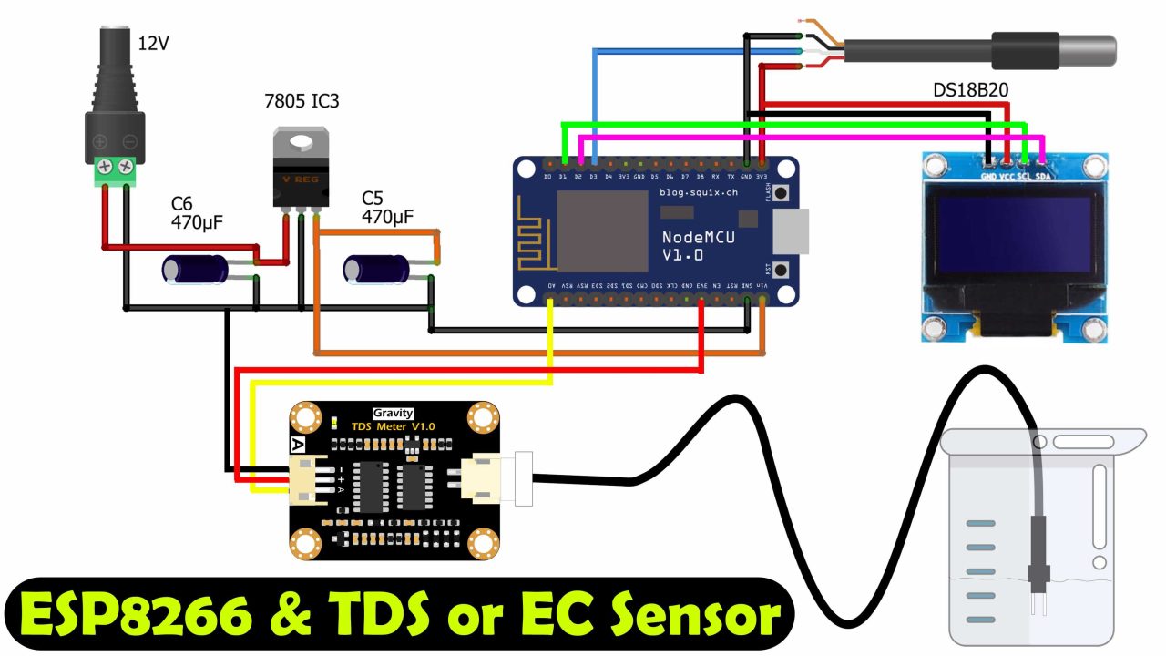
The VCC and GND pins of the I2C supported SSD1306 Oled display module are connected with the 3.3V and GND pins of the Nodemcu Module. While the SCL and SDA pins of the Oled display module are connected with the Nodemcu ESP8266 pins D1 and D2.
The VCC and GND pins of both the sensors DS18b20 and TDS Sensor interface board are connected with 3.3V and GND pins of the Nodemcu ESP8266 WiFi module.
The Data wire of the DS18b20 is connected with the digital pin D2 and the Analog output pin of the TDS or EC sensor interface board is connected with the Analog pin A0 of the Nodemcu ESP8266.
On the top left side, you can see a 5V regulated power supply based on the LM7805 voltage regulator.

This is my designed development board but it’s ok if you don’t have this, you can do all the connections on a breadboard. But if you want to make the same development board then you can download the PCB Gerber. Now, let’s go ahead and start with the Blynk.
Creating Blynk Web Dashboard:
Open your Blynk.cloud dashboard and click on the templates available on left side and then click on the New Template as you can see on the right side.

Enter the template name, select the Hardware type, select Connection type, you can also write a description, and finally, click on the Done button.

On the info tab you will see the BLYNK_TEMPLATE_ID and BLYNK_DEVICE_NAME. Next, click on the Datastreams.

Click on the New Datastream and select Virtual Pin

Enter the pin name, select virtual pin “in my case V0”, Data type, minimum and maximum value and click on the create button. You can see in the image below, I have selected a maximum value of 200, but later I changed this value. Anyway, when you are done with filling all the values then you can click on the Create button.

In similar way.I added two more virtual variables for the EC value and temperature. Once I created all the three virtual variables for the TDS, EC, and Temp then I clicked on the Web Dashboard.

Then in the web dashboard select the gauge and drag it to the dashboard.

Next, click on the Gauge gear icon to open the settings.

Now in the Gauge settings enter the title name, select the gauge data stream, and click on the save button.

Using the same exact method, I added two more gauges for the EC and Temperature. After you have added the required number of gauges then finally, you can click on the Save button.

Next, click on the search button.

Click on the new device.

Click on the From template.

Select the desired template and click on the Create button.

Then copy the blynk credentials.
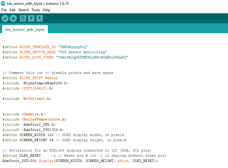
Now, we have to use the Template ID, Device Name, and Authorization Token in the programming. In the image below on the top right side, you can see the BLYNK_TEMPLATE_ID, BLYNK_DEVICE_NAME, and BLYNK_AUTH_TOKEN. We are going to use these in the programming.

Copy the TEMPLATE_ID and paste it next to the BLYNK_TEMPLATE_ID. Repeat the same steps for the Device Name and Authorization Token.
You also need to install the Nodemcu ESP8266 board in the Arduino IDE using Board manager URL url link.
You will also need to install BlynkSimpleEsp8266.h, ESP8266WiFi.h, WiFiClient.h, OneWire.h, DallasTemperature.h, Adafruit_GFX.h, and Adafruit_SSD1306.h libraries for this you can read my getting started articles on the Nodemcu ESP8266 WiFi Module and New Blynk V2.0,DS18b20, and SSD1306 Oled Display Module.
TDS Sensor ESP8266 Programming:
|
1 2 3 4 5 6 7 8 9 10 11 12 13 14 15 16 17 18 19 20 21 22 23 24 25 26 27 28 29 30 31 32 33 34 35 36 37 38 39 40 41 42 43 44 45 46 47 48 49 50 51 52 53 54 55 56 57 58 59 60 61 62 63 64 65 66 67 68 69 70 71 72 73 74 75 76 77 78 79 80 81 82 83 84 85 86 87 88 89 90 91 92 93 94 95 96 97 98 99 100 101 102 103 |
#define BLYNK_TEMPLATE_ID "TMPLNqcpqStq" #define BLYNK_DEVICE_NAME "TDS sensor monitoring" #define BLYNK_AUTH_TOKEN "5Smo4HyqpNZDMTNIyERcHUgHnuIWQqK2" // Comment this out to disable prints and save space #define BLYNK_PRINT Serial #include <BlynkSimpleEsp8266.h> #include <ESP8266WiFi.h> #include <WiFiClient.h> #include <OneWire.h> #include <DallasTemperature.h> #include <Adafruit_GFX.h> #include <Adafruit_SSD1306.h> #define SCREEN_WIDTH 128 // OLED display width, in pixels #define SCREEN_HEIGHT 64 // OLED display height, in pixels // Declaration for an SSD1306 display connected to I2C (SDA, SCL pins) #define OLED_RESET -1 // Reset pin # (or -1 if sharing Arduino reset pin) Adafruit_SSD1306 display(SCREEN_WIDTH, SCREEN_HEIGHT, &Wire, OLED_RESET); // Your WiFi credentials. // Set password to "" for open networks. char ssid[] = "AndroidAP3DEC"; char pass[] = "electroniclinic"; char auth[] = BLYNK_AUTH_TOKEN; namespace pin { const byte tds_sensor = A0; const byte one_wire_bus = D3; // Dallas Temperature Sensor } namespace device { float aref = 3.3; // Vref, this is for 3.3v compatible controller boards, for arduino use 5.0v. } namespace sensor { float ec = 0; unsigned int tds = 0; float waterTemp = 0; float ecCalibration = 1; } OneWire oneWire(pin::one_wire_bus); DallasTemperature dallasTemperature(&oneWire); void setup() { Serial.begin(115200); // Dubugging on hardware Serial 0 Blynk.begin(auth, ssid, pass); dallasTemperature.begin(); display.begin(SSD1306_SWITCHCAPVCC, 0x3C); delay(2000); display.clearDisplay(); display.setTextColor(WHITE); } void loop() { Blynk.run(); readTdsQuick(); delay(1000); } void readTdsQuick() { dallasTemperature.requestTemperatures(); sensor::waterTemp = dallasTemperature.getTempCByIndex(0); float rawEc = analogRead(pin::tds_sensor) * device::aref / 1024.0; // read the analog value more stable by the median filtering algorithm, and convert to voltage value float temperatureCoefficient = 1.0 + 0.02 * (sensor::waterTemp - 25.0); // temperature compensation formula: fFinalResult(25^C) = fFinalResult(current)/(1.0+0.02*(fTP-25.0)); sensor::ec = (rawEc / temperatureCoefficient) * sensor::ecCalibration; // temperature and calibration compensation sensor::tds = (133.42 * pow(sensor::ec, 3) - 255.86 * sensor::ec * sensor::ec + 857.39 * sensor::ec) * 0.5; //convert voltage value to tds value Serial.print(F("TDS:")); Serial.println(sensor::tds); Serial.print(F("EC:")); Serial.println(sensor::ec, 2); Serial.print(F("Temperature:")); Serial.println(sensor::waterTemp,2); display.clearDisplay(); display.setCursor(10,0); display.setTextSize(2); display.setTextColor(WHITE); display.print("TDS:"+String(sensor::tds)); display.setCursor(10,20); display.setTextSize(2); display.print("EC:"+String(sensor::ec, 2)); display.setCursor(10,45); display.setTextSize(2); display.print("T:"+String(sensor::waterTemp,2)); display.display(); Blynk.virtualWrite(V0,(sensor::tds)); Blynk.virtualWrite(V1,(sensor::ec)); Blynk.virtualWrite(V2,(sensor::waterTemp)); } |
Before, you upload the program, make sure you select the correct Nodemcu ESP8266 board, and the correct communication port. When you are done with uploading the program then you should be able to see the TDS, EC, and Temperature values on the Gauges.

Mobile dashboard creation in Blynk V2.0:
Open the Blynk app on your cell phone and click on the developer mode.

Then click on the TDS sensor monitoring.

Then click on the “+” sign to add a gauge from the widgets list.

Then click on the choose datastream

After that select the variable which you want to display on the gauge we will select the TDS.

Then set the font size.

And click on the Design to add the gauge.

Using the same exact method add the remaining two gauges but remember to use their corresponding datastreams.

You can see my mobile app is also reading and now I can also monitor the TDS, EC, and temperature values on my cell phone. For the practical demonstration, watch the video tutorial by clicking on the link given below.
Watch Video Tutorial
Discover more from Electronic Clinic
Subscribe to get the latest posts sent to your email.
Dear Mr. Shahzada
So many thanks for sharing the information and tech for Arduino IoT systems. I am one of your fan watch your Arduino related videos in YT . I am going to make a IoT systems for my own hydroponic system . I like to display water EC, pH , water temp , my small greenhouse air temp and humidity ( 5 variables with 4 sensors. ) Since there is 4 sensors, is it possible to do it only with ESP8266? or I need Arduino nano / Uno card too.
Your reply will be highly appreciated . If possible, pls. make a video for this complete system for Hydroponic Greenhouse for monitoring these 5 parameters .
Best of regards
Iftekhar
Canada