How to Set Up KME Smart IoT with ESP8266 for Smart Home Automation
Last Updated on May 11, 2026 by Engr. Shahzada Fahad
Table of Contents
Description:
Stop writing thousands of lines of code just to get a simple temperature reading on your phone. If you want to build a professional-grade IoT weather station that monitors room temperature, humidity, and even liquid temperature; all while controlling appliances remotely; you don’t need a degree in computer science.

Today, I am going to show you how to take a standard NodeMCU ESP8266 and turn it into a smart home powerhouse. We are hooking up multiple sensors and an LED as a load, and we are going to do it using a platform that makes the whole process effortless.
To make all this hardware talk to the internet, we need a cloud platform that is powerful but easy to setup. That is why for this project, we are using KME Smart.
Getting started with KME Smart:
I am on their homepage right now at KMESmart, and this is going to be the brain of our operation.

Right off the bat, look at that tagline: “Speak to control your living space.” That is exactly what we want; effortless, hands-free control. But what catches my eye here is that KME Smart isn’t just about selling you a smart bulb; it looks like a full ecosystem.
They cover everything from smart device installation to configuration tools and check this out;

They support all the major protocols like WiFi, Bluetooth, Zigbee, and even LoRa. Plus, for those of us deep in the ecosystem, it works right out of the box with Google Home and Alexa.
Hardware Overview:
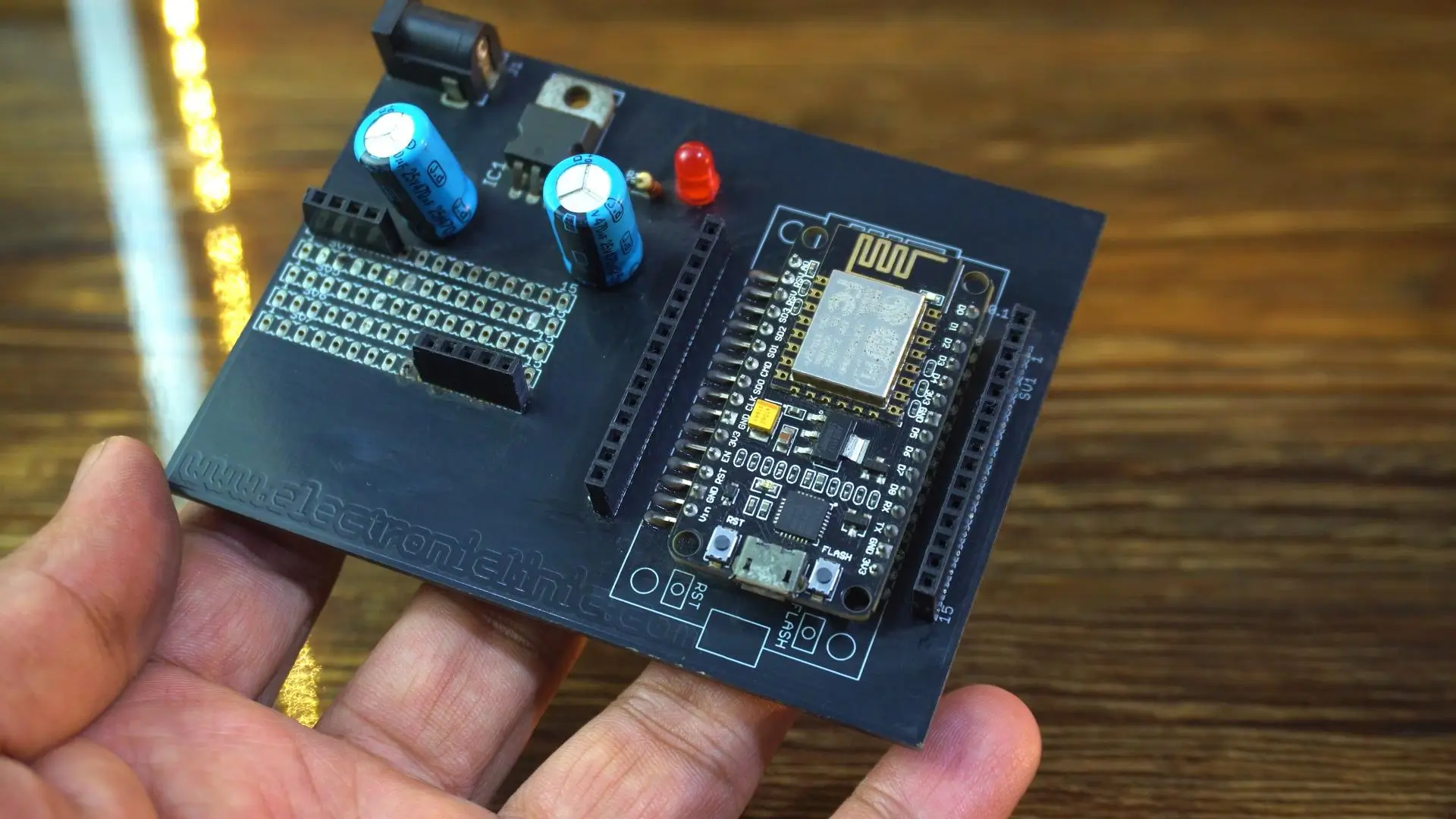
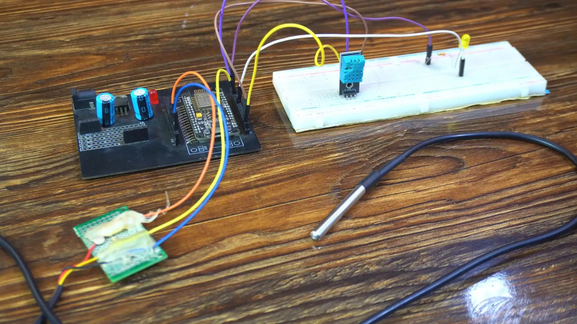
For this build, we are using the NodeMCU ESP8266 as our main controller.
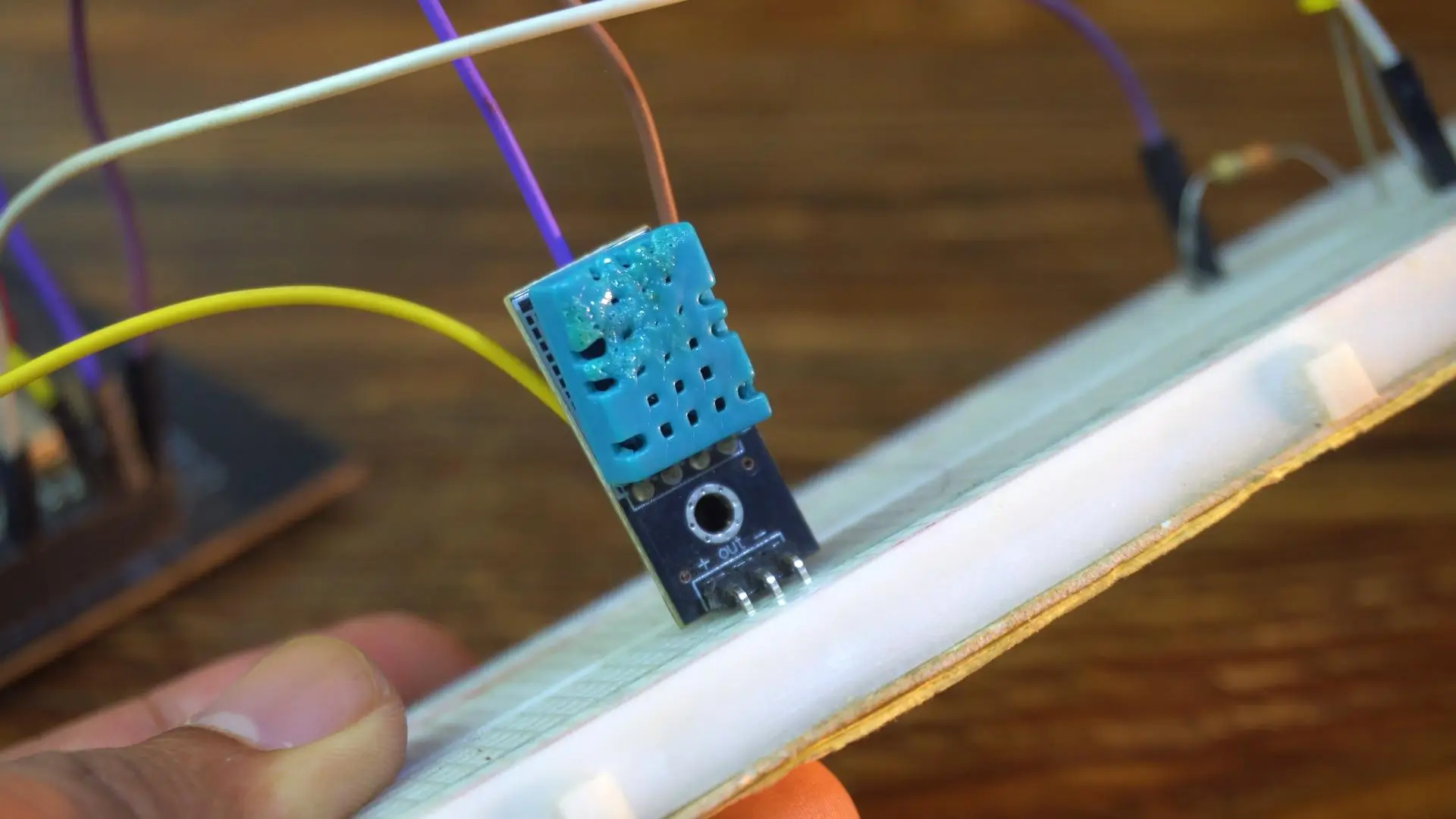
For environmental data, we have the DHT11 sensor to track the room’s air temperature and humidity.
We are also adding this;

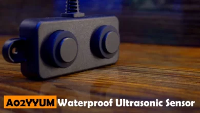
The DS18B20. This is a waterproof, one-wire digital sensor, perfect for measuring liquids or outdoor conditions.
And finally, we have a standard LED. Now, in this video, the LED is just a demonstration, but keep in mind: you can easily replace this LED with a Relay Module or a MOSFET to control high-power devices like heaters, fans, or AC units.
Circuit Diagram:

Both the DHT11 and the DS18B20 need 3.3 Volts.
So, connect the VCC pins of both sensors to the 3V3 pin on the NodeMCU.
Next, connect the Ground pins of both sensors to the GND pin on the NodeMCU.
Now for the Data lines.
Let’s start with the waterproof sensor. Take the Signal pin of the DS18B20 and connect it to GPIO 4, which is labeled as D2 on the board. [Note: If you are using the bare sensor, don’t forget the 4.7k or 330-ohm pull-up resistor between data and power as shown in the diagram].
Next, the DHT11 sensor. Connect the Signal pin of the DHT11 to GPIO 5, which is the D1 pin on your board.
Finally, the Output.
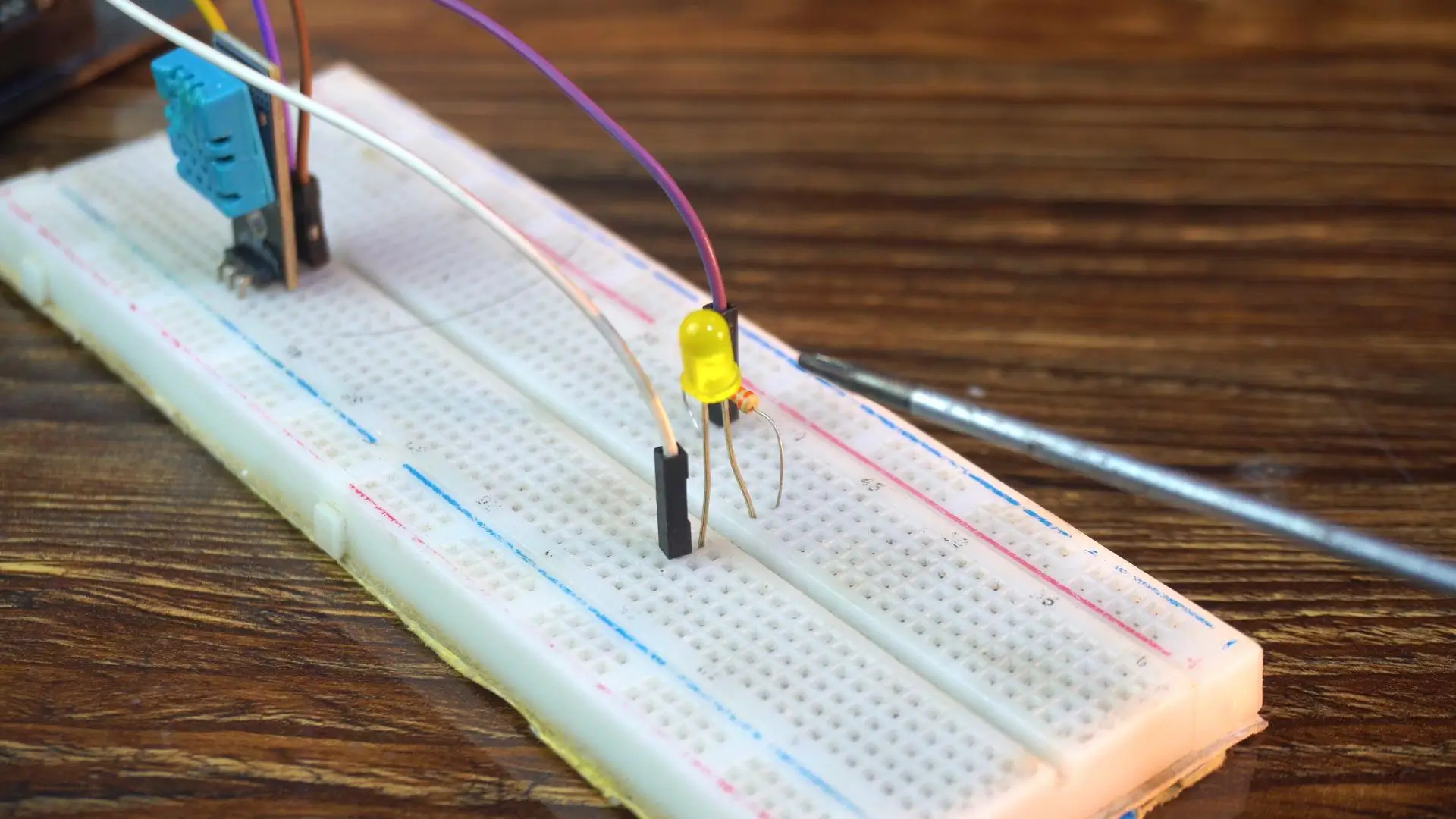
We want to control that LED.
Connect the Cathode (the short leg) to Ground.
Connect the Anode (the long leg) to GPIO 16, which is labeled as D0.
Make sure you have a resistor in series with the LED, like the 330-ohm one shown here, to prevent it from burning out.
And that is it! The hardware is ready.
Amazon Links:
DS18b20 Waterproof Temperature Sensor
DHT11 Temperature and Humidity Sensor
Other Tools and Components:
ESP32 WiFi + Bluetooth Module (Recommended)
Arduino Nano USB C type (Recommended)
*Please Note: These are affiliate links. I may make a commission if you buy the components through these links. I would appreciate your support in this way!
Desktop Configuration (Flashing & Setup)

Now, let’s jump into the configuration.

You can see the Supported Modules list. Right now, they have full support for the industry standards; we are talking the classic ESP8266, the ESP32, and even the newer S3 and C3 variants. This means you aren’t locked into just one type of board.
But what I really like is that they are transparent about their roadmap. Look at this right here: “ESP8285 – SOON”.
It’s a small detail, but it shows that the platform is active and evolving. So, whether you are using a standard NodeMCU today or planning a compact build with an 8285 in the future, KME Smart is getting ready for it.
This page is also where you will find the pinout guides for every widget; from Relays to RGB strips.
Now, usually, when we talk about cloud platforms and professional dashboards, there is a catch; and it’s usually a monthly subscription.
But this is where KME Smart actually surprised me. If you look at their license information, they have taken a completely different approach. They offer a Lifetime License.

That means no monthly fees and no yearly renewals. You pay once; it’s just $5 per device and you own that access forever. It even comes with a 2-year warranty for updates and support, which is pretty rare in the DIY IoT space.
And the best part? You don’t have to pay a single penny to get started. They give you a 30-day Free Trial for every device. So you can build this entire project, test it out, and see if you like it before you commit.
Honestly, in a world where everything is becoming a subscription service, seeing a one-time $5 fee for lifetime access is really refreshing.
Now, right there you see that Windows button.
This button downloads the KME Config Tool, which is the desktop application we are going to use. Think of this app as the “bridge” between the website and your ESP board.
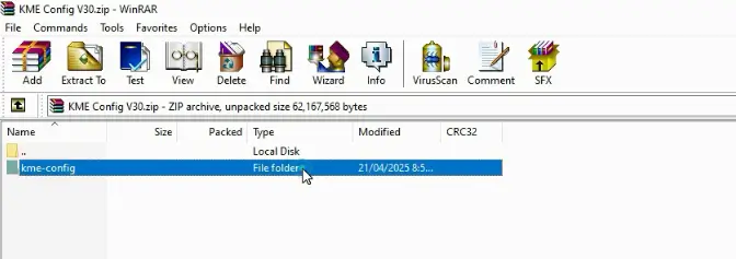
Once the download is finished, extract the folder and launch the config.exe file.
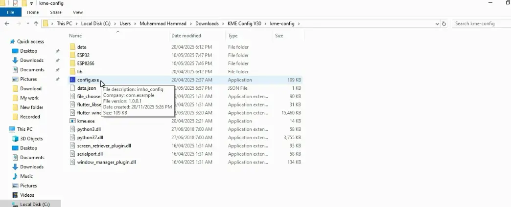
This opens up the configuration interface where we can flash the firmware directly to our NodeMCU.
While your NodeMCU is connected to your PC.
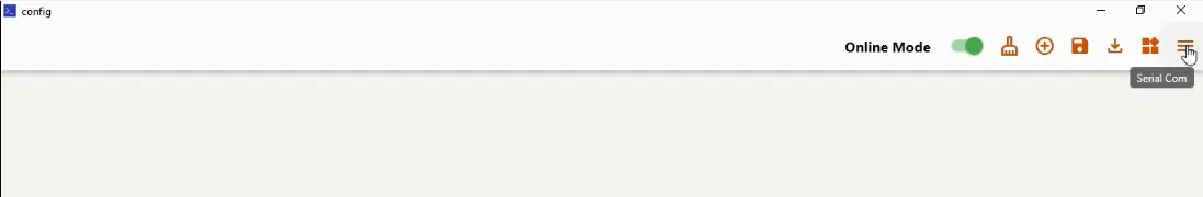
Go to the Serial COM section, select your board’s COM port, and hit Connect.
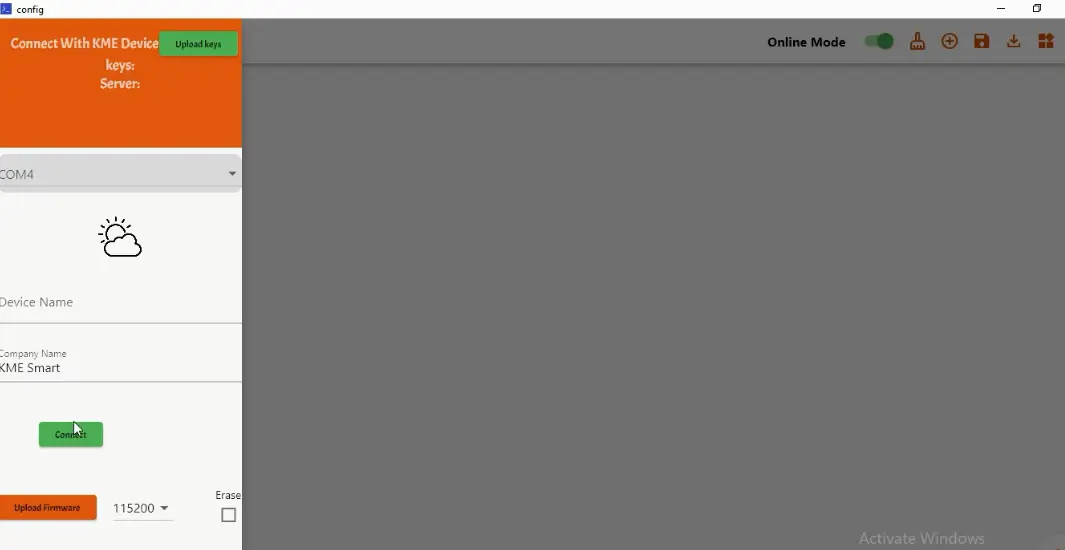
The tool should automatically detect your board. Once it does, simply click Upload Firmware.
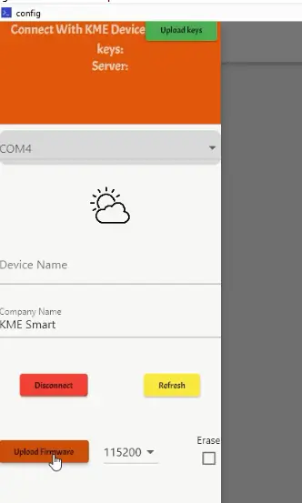
Let that run for a moment.
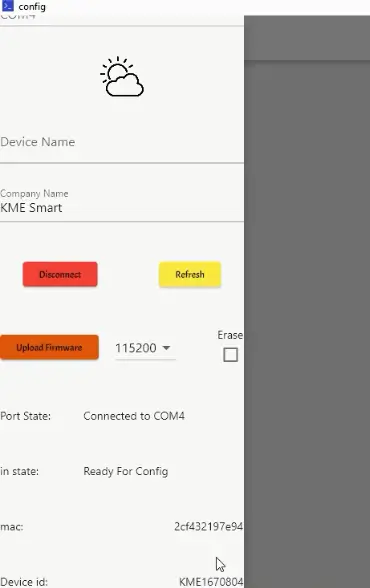
Once the upload is complete, you will see a unique MAC address and Device ID appear on the screen. This means we are online!
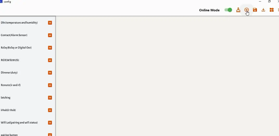
Now, let’s tell the board what sensors we are using.
Click the Plus (+) button to open the widget menu.
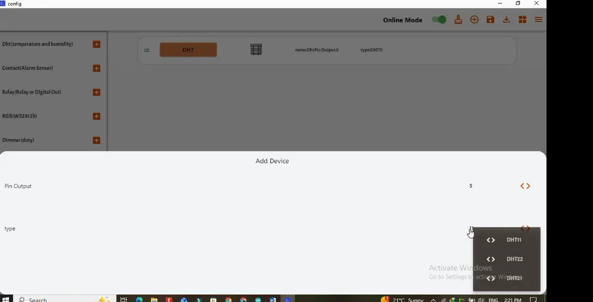
First, click on the DHT Sensor to add it to the dashboard. Double-click the widget to configure it:

Select your sensor type and set the pin to GPIO 5 (D1).
Next, add the DS18B20 widget.
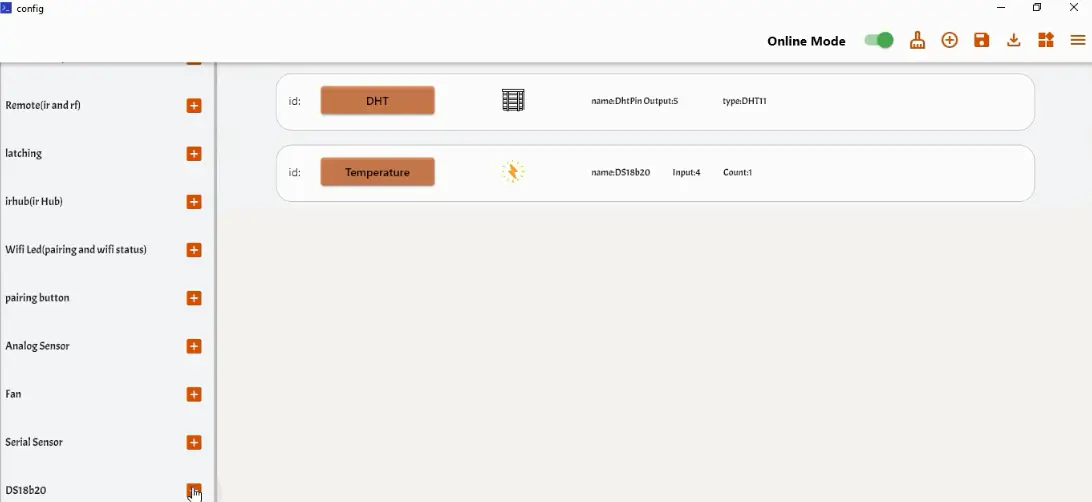
Open the settings and assign it to GPIO 4 (D2).

Finally, add a Relay widget to control our LED.
Map this to GPIO 16 (D0).

Feel free to rename the modules; trust me, it makes navigating your setup far easier.
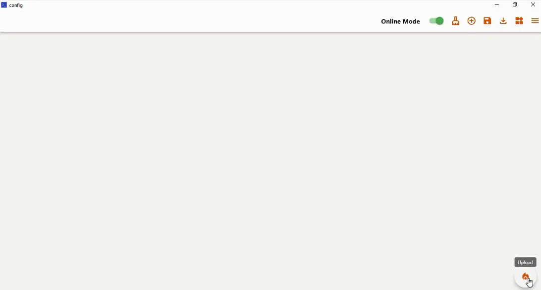
Once your widgets are set, click Save Dashboard.
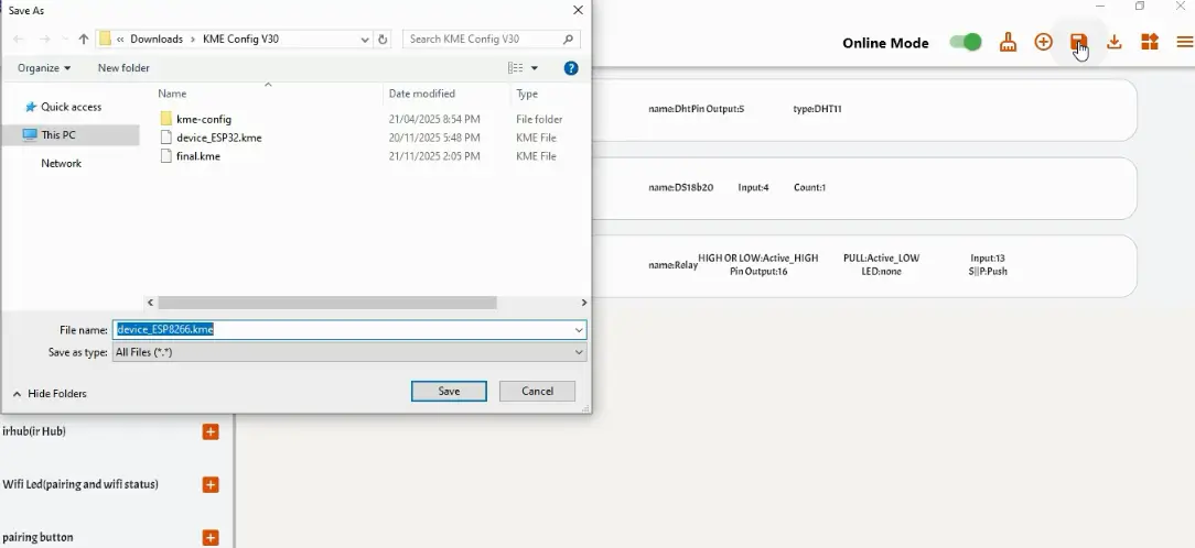
Next; if those icons aren’t your style, go ahead and change them. Make the interface truly yours.

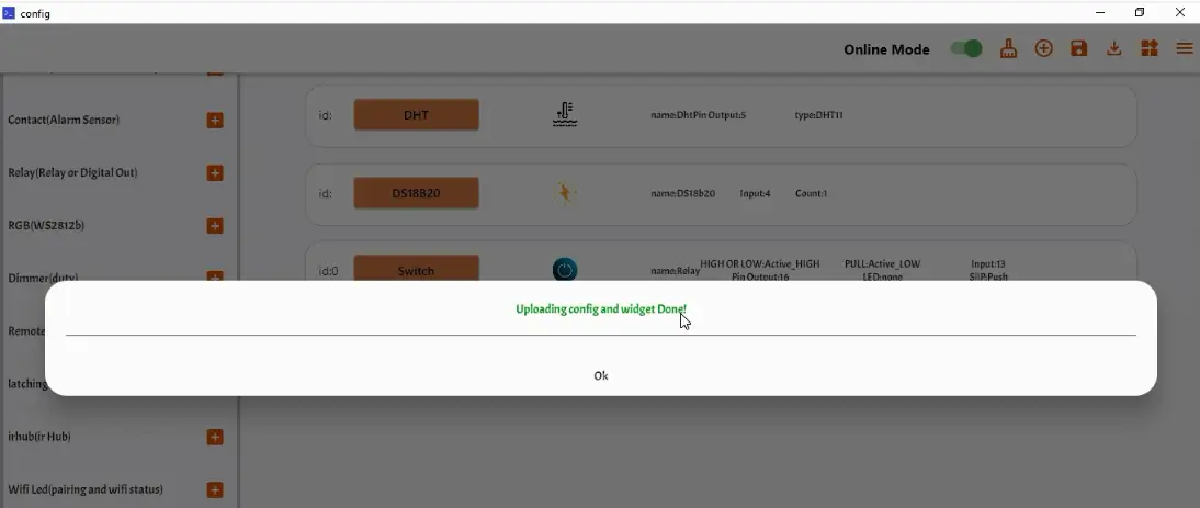
And then hit Upload. Within seconds, your configuration is flashed to the chip.
Mobile App Setup (Connection)
With the board ready, let’s move over to the phone to control it.
Go to the Play Store and download the KME Smart app.
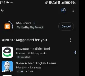
Open it up, tap Register, and quickly create your account. Once you are signed up, log in with your email and password.
Now, let’s pair the device.
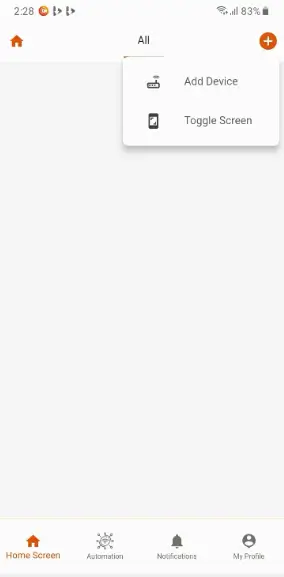
Tap the Add Button (+) to add a new device.
Enter your WiFi credentials. Important:

Make sure you enter the WiFi name and password correctly, as the app will transfer these details to the ESP8266.
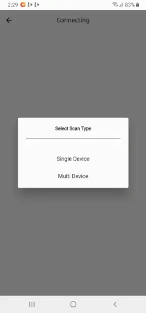
Select ‘Via Smart Connect’ and then choose “Single Device”.

Now, look at your hardware. Press and hold the Flash/Boot button on the NodeMCU for about three seconds until the onboard LED starts blinking. This puts it into pairing mode.
Back on the app, the device automation should appear; just tap Add Device.
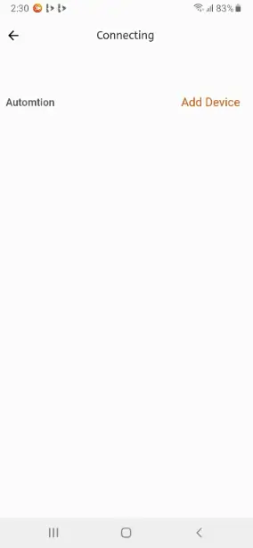
You can rename it here if you like.
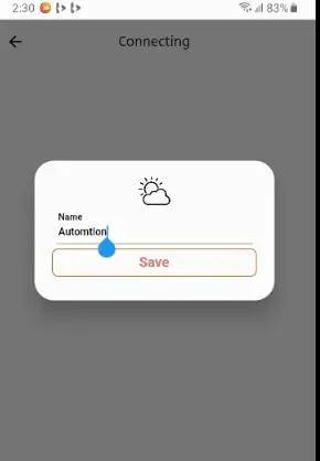
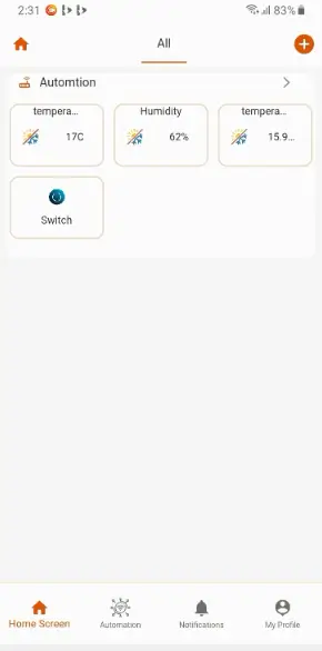
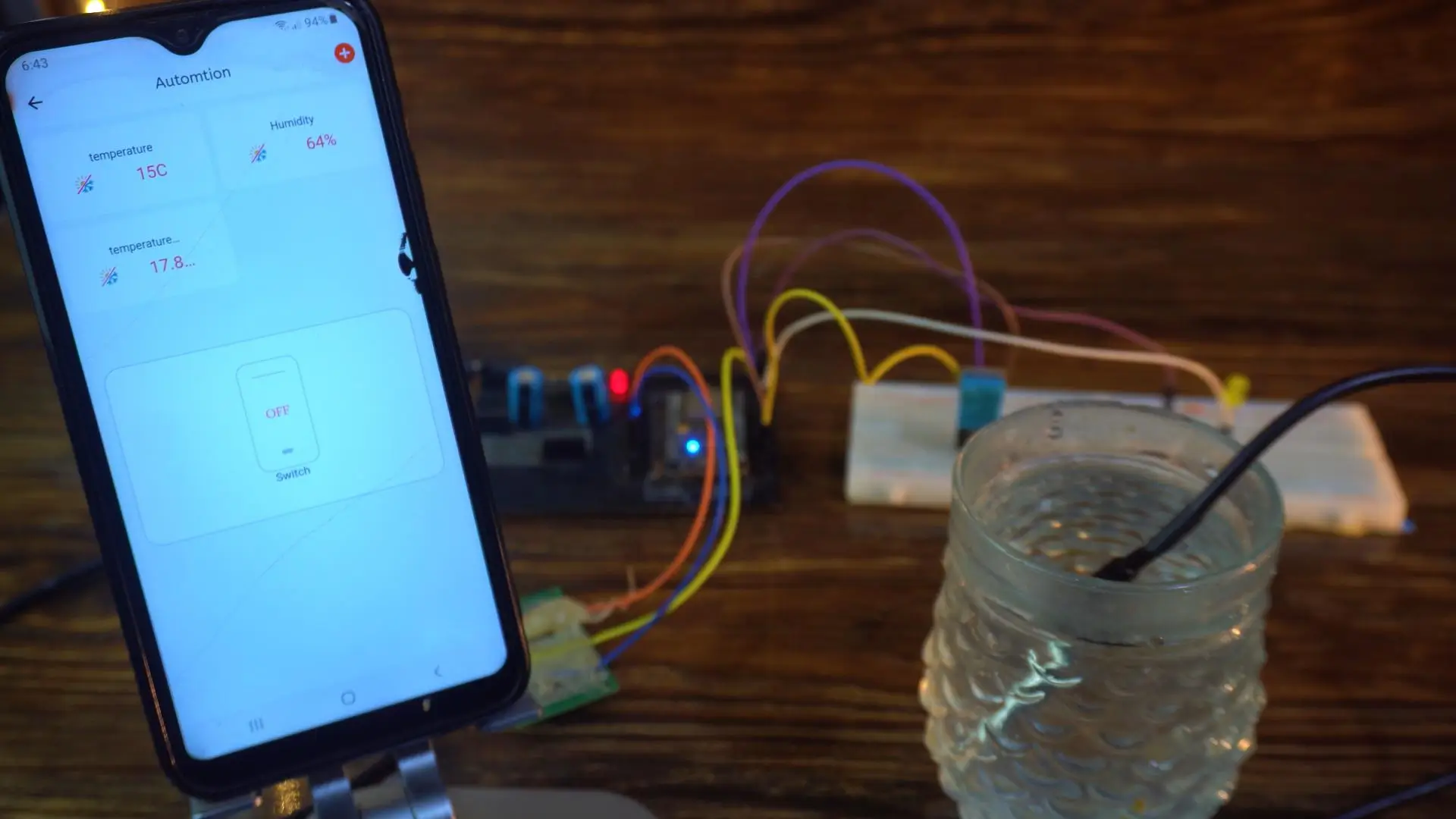
And there we go! After just a few seconds, live temperature and humidity data is streaming straight from our circuit to the phone, and we have full control over the LED.
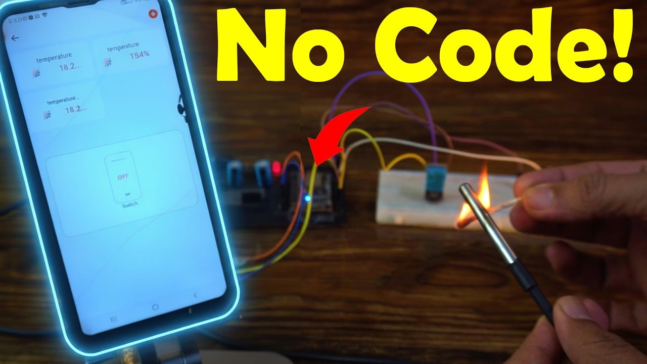
Let me heat up the sensor so you can see it in action.
KME Smart and NodeMCU:

The response is instant, precise, and honestly—pretty impressive.
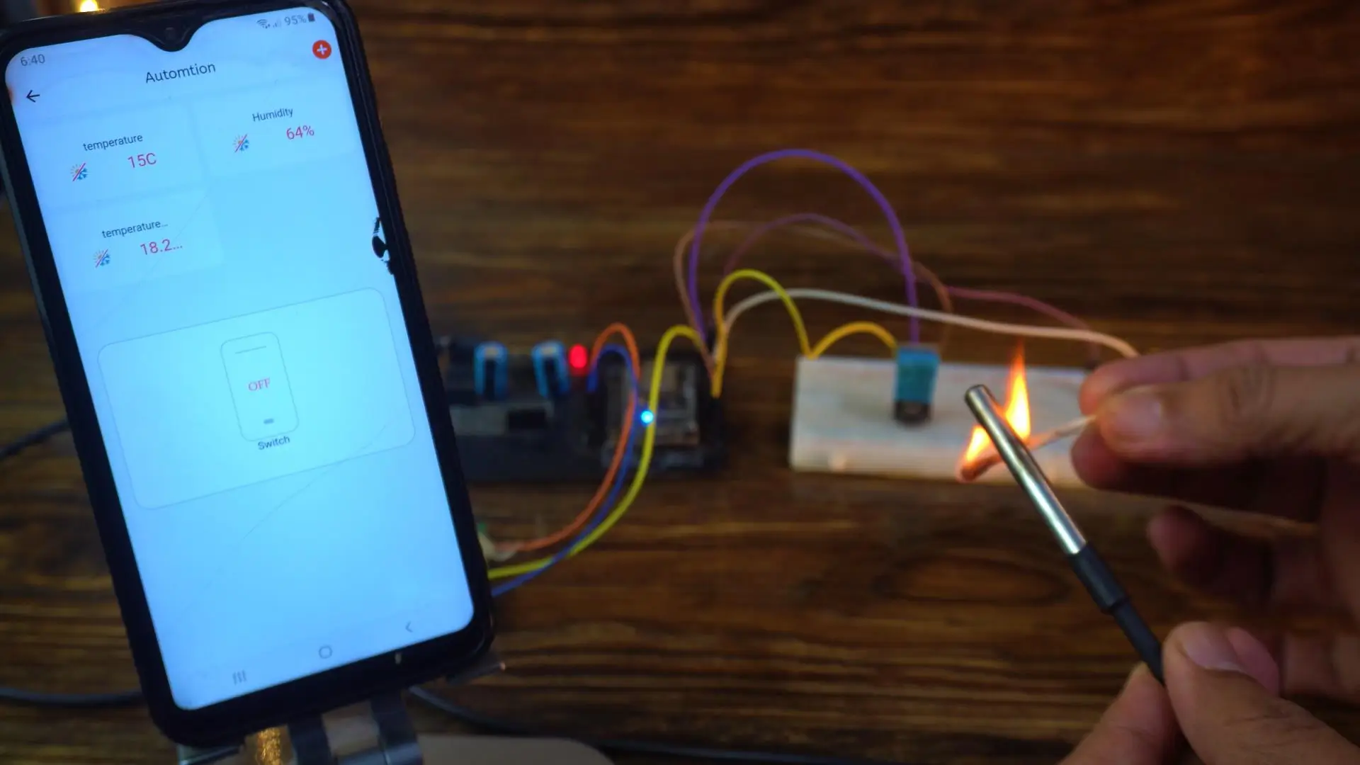
The temperature instantly raised and I was like WoW!
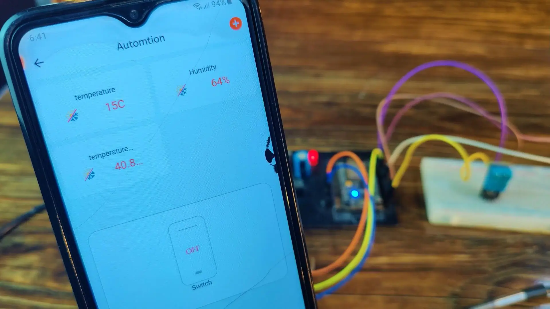
From one corner of the world to another, I can monitor everything—temperature, humidity—all live, all through the KME Smart IoT Cloud platform.
So basically, with the DHT11 sensor, I can monitor the temperature and humidity inside any room; and I can also track liquid temperature, whether it’s water or something entirely different.
And as you can see, the temperature drops instantly… that’s how responsive this setup is.
Watch Video Tutorial:
Troubleshooting — When KME Smart and ESP8266 Are Not Cooperating
Problem 1: The KME Smart app cannot find the NodeMCU ESP8266 during the pairing process
You pressed and held the Flash button for three seconds, the onboard LED is blinking to indicate pairing mode, but the KME Smart app keeps searching and never finds the device. This is one of the most common first-time setup frustrations and it usually comes down to your phone’s WiFi settings.
The KME Smart Smart Connect pairing process works by temporarily connecting your phone to the ESP8266’s own WiFi signal. Make sure your phone’s WiFi is turned on and that you have entered the correct home network credentials in the app before starting the pairing process. KME Smart uses these credentials to configure the ESP8266 to connect to your router — if the WiFi name or password has even one wrong character, the pairing will fail silently.
Also confirm that your home router is broadcasting on the 2.4GHz band. The ESP8266 is a 2.4GHz only device and cannot connect to a 5GHz network. Many modern dual-band routers broadcast both frequencies under the same network name, but if your phone has connected to the 5GHz band when you start pairing, the ESP8266 will receive 5GHz credentials it cannot use. To avoid this, temporarily connect your phone to the 2.4GHz band specifically before starting the KME Smart setup.
Problem 2: Device was added successfully but it shows as offline in the KME Smart app
The device appears in your app dashboard with its name and widgets, but there is a grey offline indicator and no live data is coming through. The LED on the NodeMCU is either not blinking or blinking rapidly indicating it is trying to reconnect.
The most common cause is that the ESP8266 connected to the 2.4GHz network during setup but later switched or the router changed something. Open the Serial Monitor at 115200 baud rate on your computer to see what the ESP8266 is doing. If you see repeated WiFi connection attempts, the board is trying to connect but failing — this usually means the router’s DHCP lease table is full or the router restarted and assigned a different channel.
Restart your router, wait 60 seconds, then power the ESP8266 off and on again. In most cases this alone restores the connection. If the device remains offline, remove it from the KME Smart app and re-pair it from scratch — the pairing process only takes about 2 minutes and often resolves persistent offline issues more reliably than troubleshooting the connection.
Problem 3: DHT11 sensor readings are showing but the values look wrong — temperature shows much higher or lower than actual room temperature
The DHT11 is reading but the numbers on your phone do not match the real temperature in the room. This is not usually a KME Smart problem — it is a physical placement issue with the sensor.
The DHT11 is very sensitive to its immediate environment. If the sensor is sitting directly on or near the NodeMCU board, the heat generated by the ESP8266’s WiFi radio slightly warms the air around the sensor and you get readings 2 to 4 degrees higher than the actual room temperature. Move the DHT11 away from the board using a short extension wire — even 10 centimeters of separation makes a noticeable difference in accuracy.
Also make sure the 10K pull-up resistor is connected between the data pin and VCC. Without this resistor, the DHT11 gives intermittent or unstable readings. The signal wire is also picking up noise from the WiFi transmissions without the pull-up. On the NodeMCU the data pin is GPIO 5 which is D1 on the board silkscreen — confirm this matches what is configured in the KME Smart widget settings.
Problem 4: DS18B20 waterproof sensor is showing 85°C constantly regardless of the actual temperature
A constant reading of exactly 85°C from the DS18B20 is not a real measurement — it is a specific error code that the sensor returns when it has not completed a proper temperature conversion. This almost always means the pull-up resistor is missing or incorrect.
The DS18B20 uses the OneWire protocol and requires a 4.7K ohm resistor connected between the data wire and the VCC wire. Without this specific value pull-up resistor, the sensor powers up but never completes its conversion cycle and returns 85 as a default placeholder. Check your wiring and confirm the 4.7K resistor is in place. Using a 10K resistor instead is a common mistake — it is too high a value for reliable OneWire communication and causes exactly this 85°C issue.
Also check the wire color coding on your DS18B20. The standard wiring is red for VCC, black for GND, and yellow or white for data. If you have a counterfeit or clone sensor, the wire colors are sometimes different — always confirm with a continuity test if you are unsure.
Problem 5: The relay or LED is not responding to the control button in the KME Smart app
You tap the control button on the app and nothing happens on the hardware side. The sensor data is coming through fine which means the connection is working, but the control signal is not reaching the GPIO pin.
First check that the correct GPIO pin is assigned to the relay widget in the KME Smart dashboard settings. The article uses GPIO16 which is D0 on the NodeMCU board for the LED output — but D0 has a quirk on some NodeMCU versions. At boot, D0 briefly goes LOW which can trigger a relay momentarily. If you notice the relay clicking at startup, this is why. Move your relay to GPIO5 (D1) or GPIO4 (D2) instead — these are more reliable output pins with no boot state issues.
Also confirm the relay module is powered correctly. Relay modules need a stable 5V supply and draw enough current that powering them from the NodeMCU’s 3.3V or even its Vin pin can cause voltage drops. Use a dedicated 5V power supply for the relay module and connect only the ground and signal wire to the NodeMCU.
Problem 6: KME Smart worked perfectly for weeks then suddenly stopped — device shows online but sensor data froze
If the device shows as online but the sensor values stopped updating and are stuck on the last reading, the firmware has gotten into a locked state. This happens occasionally with ESP8266 when a WiFi packet is lost mid-transmission and the board’s network stack gets confused.
A quick power cycle — unplug the NodeMCU for 10 seconds and plug it back in — almost always fixes this immediately. For a long-term solution, the ESP8266 has a built-in hardware watchdog timer that automatically restarts the board if the firmware stops running correctly. Make sure the KME Smart firmware version you are using has the watchdog enabled. If you have access to the underlying code, adding a periodic ESP.wdtFeed() call or using a software watchdog from the Ticker library prevents these frozen states from lasting more than a few minutes without a reset.
Frequently Asked Questions
Do I really need zero coding experience to use KME Smart with ESP8266?
Yes, genuinely zero coding required — and this is what makes KME Smart stand out from most other IoT platforms. With Blynk or Arduino IoT Cloud, you still need to write firmware code in Arduino IDE, install libraries, and upload it to your board. KME Smart handles the firmware flashing directly through its app using Smart Connect. You select your sensors and outputs in the app, the platform configures everything automatically, and the ESP8266 is ready to use. The only wiring you do is connecting the physical sensors to the correct GPIO pins as shown in the tutorial. For someone who wants IoT functionality without the programming learning curve, KME Smart removes a significant barrier to entry.
Can I use KME Smart with ESP32 instead of ESP8266?
Yes. KME Smart explicitly supports ESP32 including the standard ESP32, ESP32-S3, and ESP32-C3 variants. The setup process through the app is identical — the same Smart Connect pairing works for both. The ESP32 actually gives you more GPIO pins to work with and faster processing which is helpful if you want to connect more sensors simultaneously. If you are starting fresh and choosing between ESP8266 and ESP32 for a KME Smart project, ESP32 is the better choice for any project that needs more than 3 or 4 sensors.
Is KME Smart free or does it have a subscription fee?
Based on what Engr. Shahzada Fahad found during his testing, KME Smart does not charge a monthly subscription fee which is a major advantage over competitors. Most other professional IoT cloud platforms charge monthly fees for anything beyond very basic functionality. However, platform pricing can change over time so always check the current pricing on the KME Smart official website before starting a large deployment. Even if they introduce paid tiers in the future, the core functionality for personal and small-scale projects should remain accessible.
Can I replace the LED with a relay to control real home appliances?
Absolutely — and this is one of the most practical extensions of this project. The LED in the tutorial is just a safe demonstration load. In your real project, connect a 5V relay module to the same GPIO pin that controls the LED. The relay then acts as a switch for any device you want to control — a fan, a water pump, a light, a heater, or any mains-powered appliance. Always follow proper electrical safety when wiring anything to mains voltage. Use a properly rated relay for the load you are switching, keep all high-voltage wiring insulated and away from the NodeMCU, and if you are unsure about mains wiring, have a qualified electrician handle that part while you focus on the low-voltage ESP8266 side.
Does KME Smart work if my internet connection goes down temporarily?
When the internet connection drops, the KME Smart cloud cannot relay commands between your phone and the ESP8266, so remote control from outside your home network stops working during the outage. However, the sensors keep reading data locally on the ESP8266 — they do not stop functioning just because the cloud is unreachable. Once the internet connection is restored, the connection to KME Smart re-establishes automatically and live data resumes streaming to your app. For critical applications where you cannot afford any control downtime, consider a local fallback — a simple push button wired directly to the relay for manual override when the internet is unavailable.
Can KME Smart work with Google Home or Amazon Alexa for voice control?
Yes — as Engr. Shahzada Fahad mentioned in the article, KME Smart integrates with both Google Home and Amazon Alexa. This means once your ESP8266 sensors and relay are set up in KME Smart, you can link the account to Google Home or Alexa and control your devices with voice commands. “Hey Google, turn on the fan” becomes genuinely possible with this setup. The integration process is done through the respective smart home app — add KME Smart as a connected service in Google Home or Alexa, authorize the account, and your KME Smart devices appear as controllable items in the voice assistant ecosystem.
If you are stuck at any step of the KME Smart setup or your sensors are not reading correctly, leave a comment below describing exactly what happens and at which step it fails. I will help you work through it.
Discover more from Electronic Clinic
Subscribe to get the latest posts sent to your email.