Nodemcu ESP8266 Arduino IDE Board Manager URL Link Installation and First Project
Nodemcu ESP8266 Getting Started Tutorial
Table of Contents
Nodemcu ESP8266 Arduino, Description:
Nodemcu ESP8266 Arduino IDE- This is a very basic getting started tutorial on the Nodemcu ESP8266 WiFi Module developed by the Espressif Systems. I have been using Nodemcu ESP8266 for quite a long time in different IoT based projects. I am asked the same question again and again “How to install the Nodemcu ESP8266 in the Arduino IDE”, “How to use set up the library for the Blynk?”, “How to write our first program for the Nodemcu ESP8266 using the Arduino IDE?”, “Nodemcu ESP8266 Pinout and technical specification?”, and so many other questions. So, this is the reason I am writing this article to answer all your questions.
I am writing this article for the beginners having no prior knowledge of the Nodemcu ESP8266. In this article, I will explain each and every detail so that you can easily start with this amazing WiFi Module called the Nodemcu ESP8266. The best thing about the Nodemcu ESP8266 Wifi module is that it can be programmed using the Arduino IDE. But, first you will need to install the Nodemcu ESP8266 Board before you can start programming using the Arduino IDE, I will explain this in a minute. All the functions that you have been using with Arduino boards can also be used with the Nodemcu ESP8266. Remember Arduino and Nodemcu Pins are different, but the programming style is exactly the same. So, if you have ever used any of the Arduino boards(Arduino Uno, Arduino Nano, or Arduino Mega etc) then this tutorial is going to be really easy for you.
You know we have also another WiFi supported module called ESP32. ESP32 is also developed by the Espressif systems. Personally, I always prefer ESP32 over Nodemcu ESP8266 because ESP32 has many analog pins and ESP32 also has the built-in Bluetooth module. I highly recommend you should read my article on Nodemcu Vs ESP32, before you order any of these modules. You can also read my articles on Nodemcu ESP8266 Vs Arduino and how to get started with ESP32 WiFi + Bluetooth Module, in which I have explained the Pinout, technical specs, board URL link installation using the Arduino IDE, and how to control an LED.
In this article, we will cover:
Nodemcu ESP8266 Pinout explanation.
Nodemcu EP8266 Technical specifications.
Nodemcu ESP8266 Board Installation in Arduino IDE.
Blynk Library Set up using Arduino IDE.
Nodemcu ESP8266 First Project using Arduino IDE.
List of IoT projects based on Nodemcu ESP8266.
Without any further delay, let’s get started!!!
Amazon Links:
Other Tools and Components:
Super Starter kit for Beginners
PCB small portable drill machines
*Please Note: These are affiliate links. I may make a commission if you buy the components through these links. I would appreciate your support in this way!
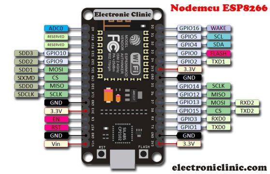
Nodemcu ESP8266 Pinout:
NodeMCU ESP8266 Wifi Module is an open-source Lua based firmware and development board specially targeted for IoT based Applications. It includes firmware that runs on the ESP8266 Wi-Fi SoC from Espressif Systems, and hardware which is based on the ESP-12 module.
Nodemcu ESP8266 Pinout:
For practical purposes ESP8266 NodeMCU V2 and V3 boards present identical pinouts. While working on the NodeMCU based projects we are interested in the following pins.
Power pins (3.3 V).
Ground pins (GND).
Analog pins (A0).
Digital pins (D0 – D8, SD2, SD3, RX and TX – GPIO XX)
Most ESP8266 NodeMCU boards have one input voltage pin (Vin), three power pins (3.3v), four ground pins (GND), one analog pin (A0) and several digital pins (GPIO XX).
Pin Code Arduino alias
A0 A0 A0
D0 GPIO 16 16
D1 GPIO 5 5
D2 GPIO 4 4
D3 GPIO 0 0
D4 GPIO 2 2
D5 GPIO 14 14
D6 GPIO 12 12
D7 GPIO 13 13
D8 GPIO 15 15
SD2 GPIO 9 9
SD3 GPIO 10 10
RX GPIO 3 3
TX GPIO 1 1
Nodemcu ESP8266 Specifications & Features
Microcontroller: Tensilica 32-bit RISC CPU Xtensa LX106
Operating Voltage: 3.3V
Input Voltage: 7-12V
Digital I/O Pins (DIO): 16
Analog Input Pins (ADC): 1
UARTs: 1
SPIs: 1
I2Cs: 1
Flash Memory: 4 MB
SRAM: 64 KB
Clock Speed: 80 MHz
USB-TTL based on CP2102 is included onboard, Enabling Plug n Play
PCB Antenna
Small Sized module to fit smartly inside your IoT projects
Applications of Nodemcu
Network projects
Low power battery operated applications
Prototyping of IoT devices
Projects requiring multiple I/O interfaces with Wi-Fi functionalities
Programming Nodemcu ESP8266 with Arduino IDE
The Nodemcu ESP8266 Development Board can be easily programmed using the Arduino IDE since it is easy to use. Setting up the Nodemcu ESP8266 with the Arduino IDE will hardly take 10-20 minutes. All you need is the latest version of the Arduino IDE, a USB cable and the Nodemcu ESP8266 board itself.
Arduino Nodemcu ESP8266 Board Installation:
Make sure a latest version of the Arduino IDE is installed on your computer. Currently I am using the Arduino IDE version 1.8.10. Copy the following URL Link given below
Nodemcu ESP8266 URL Link:
http://arduino.esp8266.com/stable/package_esp8266com_index.json
Step1:
Open your Arduino IDE
Step2:
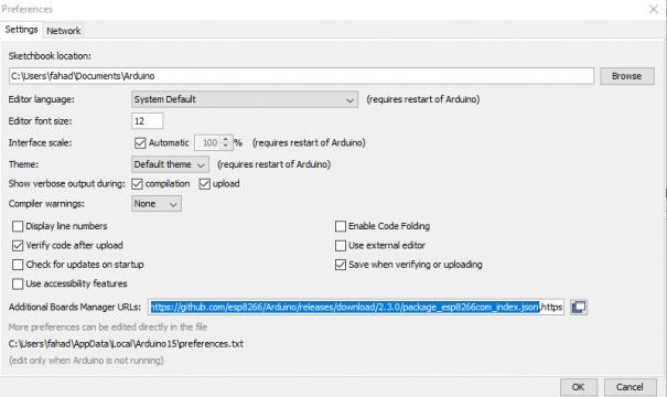
Click on the preferences and paste the URL link given above.
You can see I pasted this link in the additional Boards Manager URLs box. You are all set and now you can click on the OK button.
Step3:
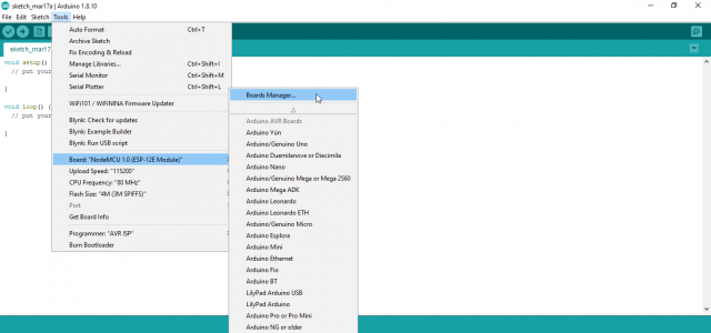
While your Arduino IDE is still opened. Click on the tools Menu > Board > Boards Manager. Click on the Boards Manager.
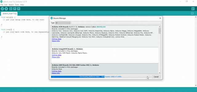
The board manager will open, and will automatically download the index
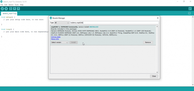
This download process may take some time depending on the speed of your internet connection. So, set back and wait for the download process to complete. When the download process is completed then in the search box type “nodemcu esp8266”. Currently, you can see my esp8266 board is installed. So, you will see the install button, click on the install button and wait.
Step4:
After your Nodemcu ESP8266 board has been installed. The final step is to close the boards Manager window. Now you will need to restart the Arduino IDE, so that the Arduino IDE can properly load all the boards.
Step5:
This is the final step to confirm if the Nodemcu ESP8266 board is installed.
Click on the tools menu > boards, scroll down and find the Nodemcu as you can see in the image above. If you can see the same then you are all set. We are done with the hard part. Now, you can start programming the Nodemcu ESP8266 WiFi module.
Note: this old version of the Blynk app is no more functional. For the blynk mobile App setup and Blynk.cloud dashboard setup ready my article on the New Blynk V2.0. In this article I have explained how to migrate your projects from Blynk 1.0 to the new Blynk V2.0. You can also watch the video.
Blynk Library Set Up:
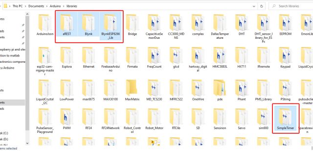
For the remote monitoring and controlling you will need an IoT platform, e.g Thingspeak, Ubidots, or the Blynk Application etc. Since Blynk Application is very easy and it’s free, I always recommend Blynk Application for the beginners. Download the following Libraries.
Download these libraries, extract them, then copy the folders and past them in the Arduino libraries folder which you can find the documents folder.
You can also download all the libraries I have been using. Anyways, after download the required libraries, now we can start making different projects. For the beginners I always recommend to start with something which is easy. How about controlling an LED from anywhere around the world using the Blynk application? Let’s do it.
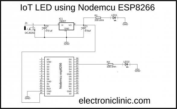
LED with Nodemcu ESP8266, Circuit Diagram:
If you are planning to power up your Nodemcu ESP8266 module using your laptop or computer then there is no need to add the power supply circuit based on the 7805 voltage regulator. You can only connect the 330 ohm resistor and the 2.5V LED. This set up is enough to get started with the Nodemcu ESP8266. But
Things will get complicated a little when you decide to use external power supply to power up the Nodemcu ESP8266 Module and moreover it seems impractical to use your laptop or computer to power up the Nodemcu ESP8266 all the time. Use your laptop or computer only for the programming and uploading the code. When the program is uploaded then you can disconnect your Nodemcu module from the computer and use any voltage source between 9 and 25 volts to power up the Nodemcu module. You don’t need to be worried about the voltage, the 7805 regulator will regulate the voltage at 5 volts, and don’t forget to add these 470uF decoupling capacitors. J1 is the input DC female power jack.
IoT LED, Blynk Application:
Prior to the Nodemcu ESP8266 programming, I decided first to make the blynk application. This way I know exactly how many virtual pins I will need to use in the final code. And this also helps me in troubleshooting.
Make sure you have downloaded and installed the Blynk application.
- First of all, open the blynk application.
- Click on the new project and enter the project name as “nodemcu”. If you want you can select any other name. Later you can modify the project name.
- Click on the choose device and select Nodemcu.
- Make sure the connection type is set to WIFI.
- Finally, click on the create button, an authentication token will be sent on your email id, which later will be used in the Nodemcu programming.
- Click anywhere on the screen and add a button.
- Click on the button to open the button settings.
- Write name of the button.
- Click on the PIN and select Digital and select the pin D2.
- Select the Mode as SWITCH.
- You can also change the Fonts size. So that, all.
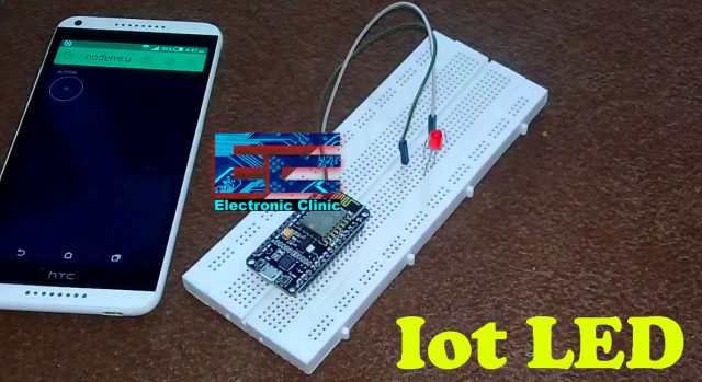
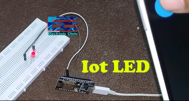
In the image you can see I am not using any power supply, as I am planning to use my laptop. The Nodemcu ESP8266 Module is very breadboard friendly. I connected the LED with the Nodemcu module as per the circuit diagram. Your application should look something like as you can see in the image above.
Our application is ready and also our hardware is ready. Now we can start the programming. Before you start the programming, first of all, make sure you download all the necessary libraries, the download links are already given above.
IoT LED, Nodemcu ESP8266 Programming:
|
1 2 3 4 5 6 7 8 9 10 11 12 13 14 15 16 17 18 19 |
#define BLYNK_PRINT Serial #include <ESP8266WiFi.h> #include <BlynkSimpleEsp8266.h> char auth[] = "60ac5cfe78444a9f8d938f9a7555d629"; // this is the authentication token char ssid[] = "My_Wifi"; char pass[] = "electroniclinic"; void setup() { pinMode(D2, OUTPUT); // ON/OFF Blynk.begin(auth, ssid, pass); } void loop() { Blynk.run(); } |
Final Testing:
Upload the code given above. Open your blynk application, Click the play button on the App and then start controlling the LED using your cell phone. As this is based on the IoT so you can control this LED from anywhere around the world.
I successfully controlled the LED using my cell phone. For more beginners level, Intermediate level, and Advanced level projects…
Other Nodemcu ESP8266 and ESP32 Related projects:



Hello, I cant seem to find any video about how to use the notifications on the new blynk version, would you be able to tell me how to do it?