ESP8266, PN532 RFID, and Google Spreadsheet based In/Out Time Tracking System
Google Sheet Tracker
Last Updated on September 21, 2024 by Engr. Shahzada Fahad
Table of Contents
ESP8266, PN532 RFID, & Google Spreadsheet:
ESP8266, PN532 RFID, and Google Spreadsheet based In/Out Time Tracking System- In today’s article, you will learn how to make an IoT based In/Out Time Tracking System using the Nodemcu ESP8266 WiFi Module, the PN532 NFC RFID Module, an I2C-supported SSD1306 Oled Display Module, and Google Spreadsheet or Google sheets.
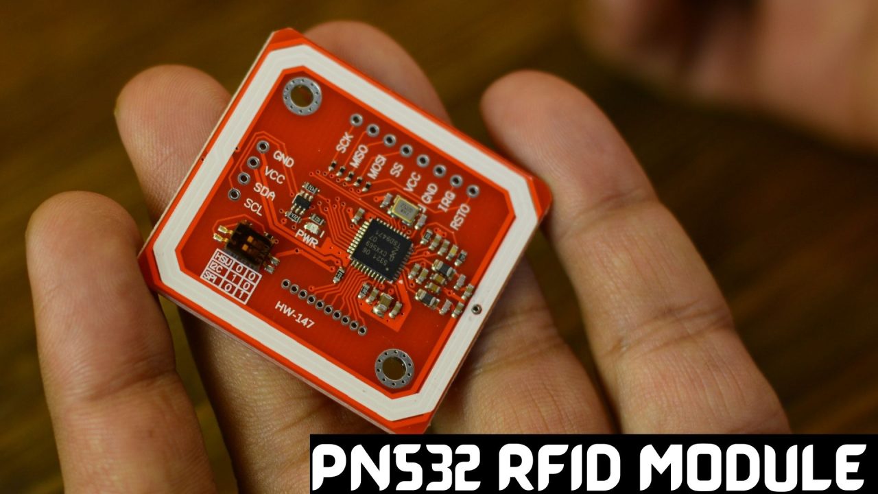
The reason I selected the PN532 RFID module is that it’s a low-cost and low-power RFID module. And it supports multiple interfaces HSU “ High Speed UART”, I2C, and SPI. In my previous article, I have already explained how to use all three interfaces.
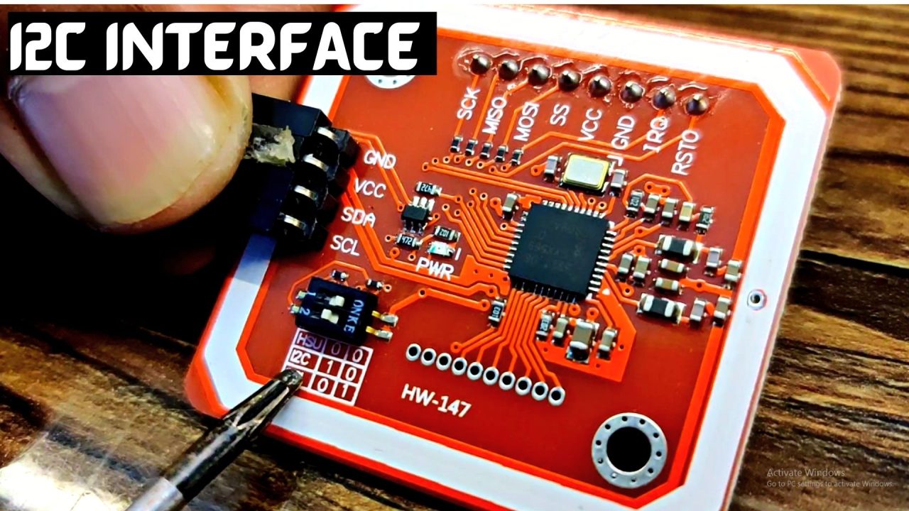
In this article, I am going to use the I2C interface because my Oled display module is also an I2C-supported device, so using the I2C interface I can reduce the wiring. So, using only two pins on the Nodemcu ESP8266, I can communicate with both modules.
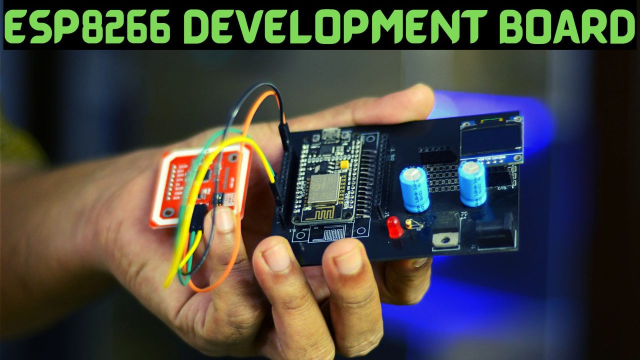
As usual, I am using the same ESP8266 development board. It doesn’t matter if you don’t have this development board you can do all the connections on a breadboard. Let me show you all the connections.
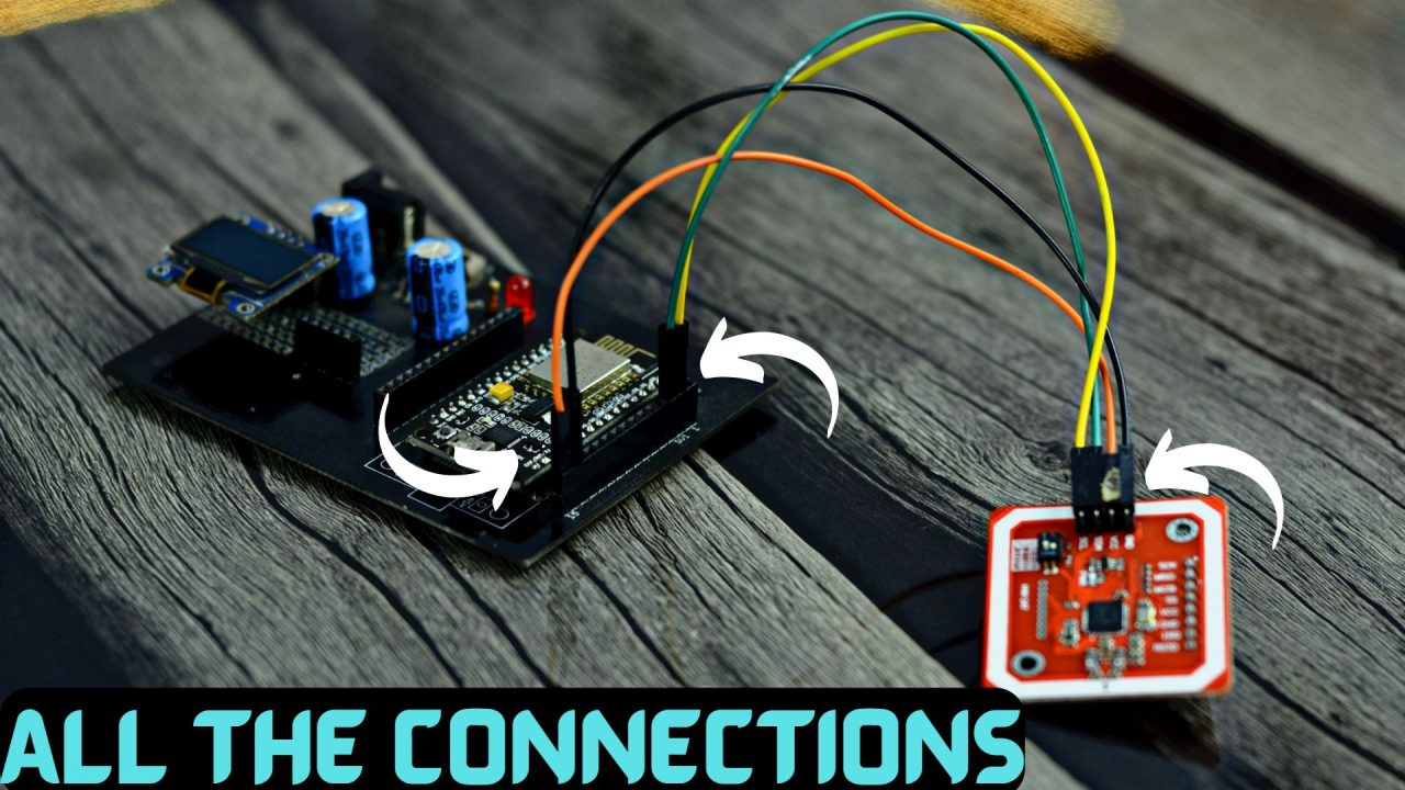
The SDA and SCL pins of the PN532 RFID module are connected with the Nodemcu ESP8266 WiFi module D1 and D2 pins. D1 is the SCL and D2 is the SDA. Likewise, the SDA and SCL pins of the SSD1306 Oled display module are connected with the same pins D1 and D2 on the Nodemcu Module. So, using these two pins we can communicate with both modules and this is only possible because of the I2C addresses. These modules have different I2C addresses.
The VCC and GND pins of the Oled display and the RFID module are connected with the 3.3V and GND pins of the Nodemcu module. If you face any difficulty in doing all these connections then you can follow this circuit diagram.
PN532 Rfid Module interfacing with ESP8266:
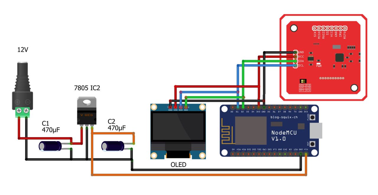
First we will connect the RFID with ESP8266:
- Connect the SCL pin of the RFID with D1 pin of the ESP8266
- Connect the SDA pin of the RFID with D2 pin of the ESP8266
- Connect the VCC of the RFID with 3.3V of the ESP8266
- Connect the GND of the RFID with GND of the ESP8266
Then connect the OLED with ESP8266
- Connect the SCL pin of the OLED with D1 pin of the ESP8266
- Connect the SDA pin of the OLED with D2 pin of the ESP8266
- Connect the VCC of the OLED with 3.3V of the ESP8266
Connect the GND of the OLED with GND of the ESP8266
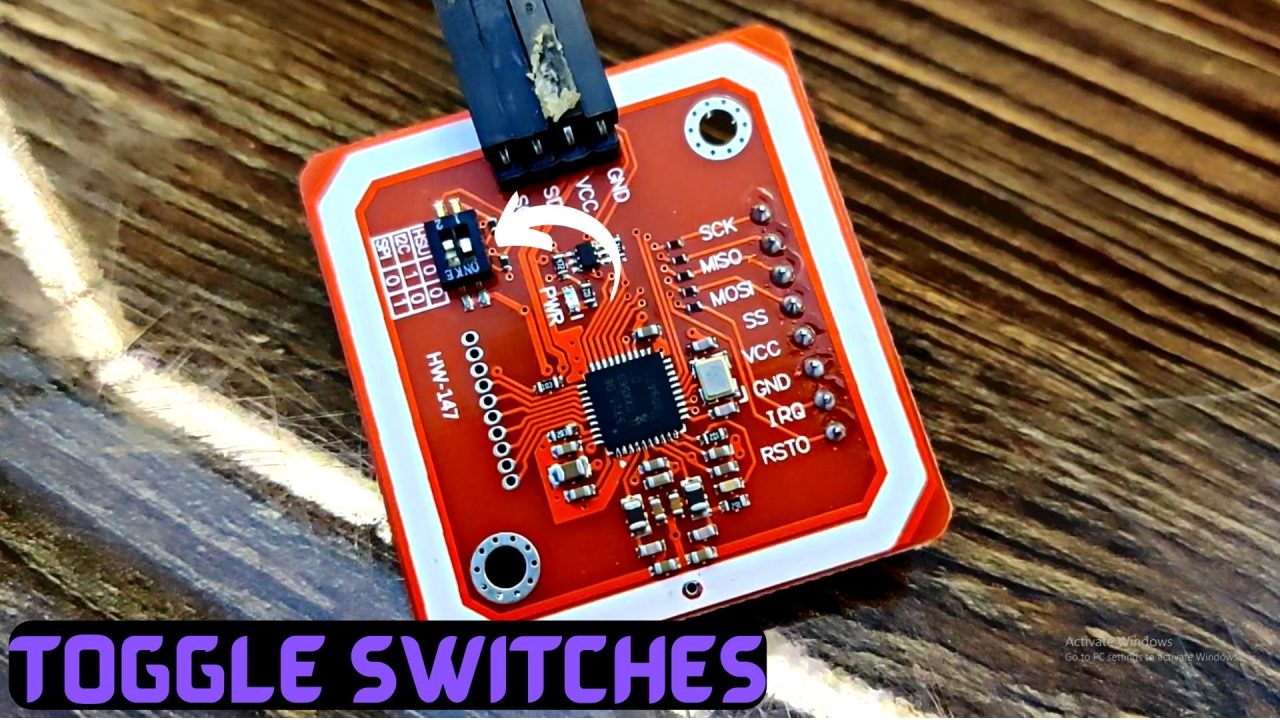
One more thing that I would like to talk about is, as I said earlier the PN532 supports multiple interfaces which are UART, I2C, and SPI. For selecting any of these interfaces you will need to accordingly adjust the toggle switches. Since I am using an I2C interface so that’s why channel 1 is ON and channel 2 is OFF.
As usual, before, I am going to explain how to set up your Google Spreadsheet and how to connect it with the Nodemcu ESP8266 WiFi module. First, let’s watch this project in action.
Practical demonstration:
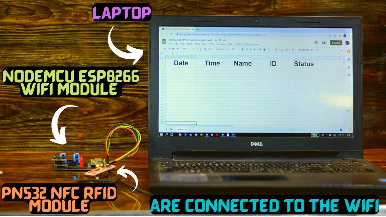
Right now, my Nodemcu ESP8266 WiFi Module and Laptop are connected to the WiFi. Let me also tell you, it’s not necessary to use the same WiFi network, you can use different WiFi networks. It’s an IoT project, you can monitor the employees or students in/out of time from any part of the world.
Anyway, on the Google spreadsheet, I can monitor the Date, Time, Name of the employee or a student, the ID, and the in/out status.
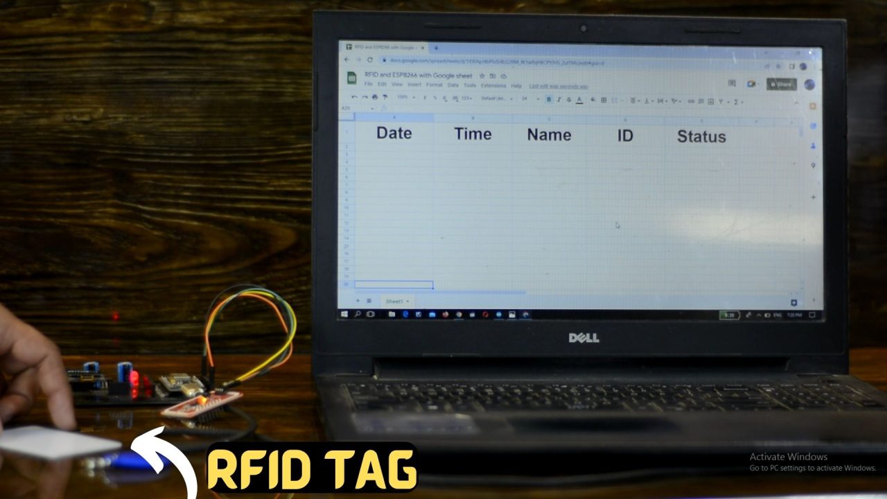
I am going to swipe the RFID tags and you will practically see how it works.
The Oled display module is optional, if you remove this it won’t have any effect on the project. But it’s good to use a display, because without the display you will be confused and you won’t be sure if the card is successfully swiped.
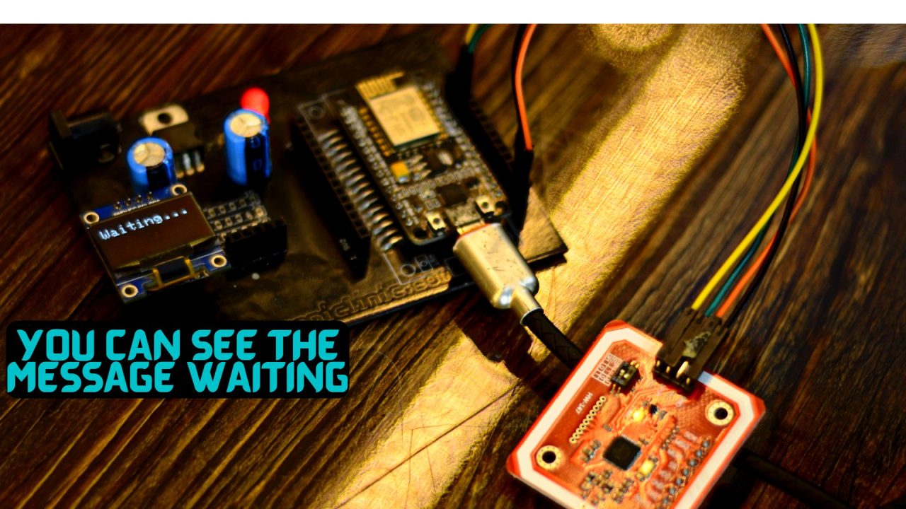
Right now, on the Oled display, you can see the message waiting…
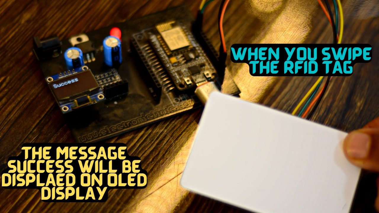
this means you can swipe the RFID tag, and when it reads the RFID tag, the message Success is printed on the display. I am sure by now, you might have got an idea of how this system works. So, without any further delay let’s get started!!!
Amazon Links:
Disclosure: These are affiliate links. As an Amazon Associate I earn from qualifying purchases.
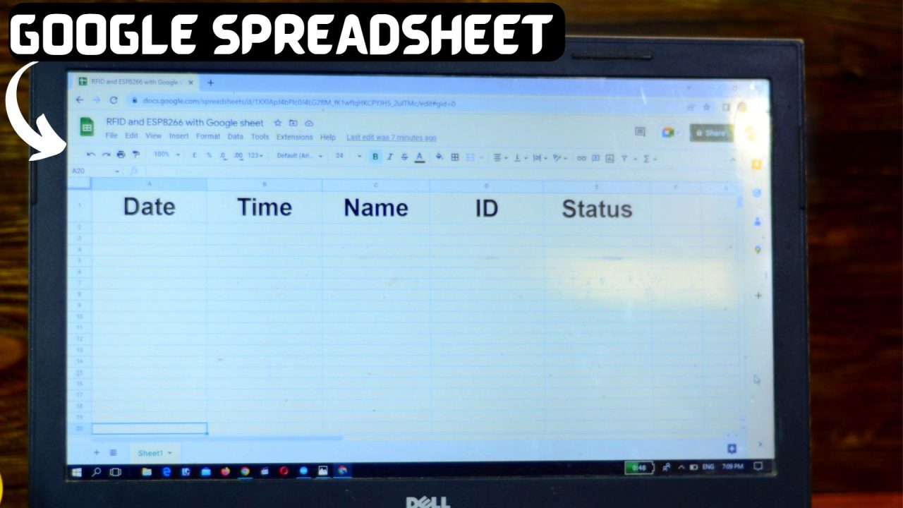
Google Spreadsheet Setup:
You will need to carefully set up your Google Spreadsheet or Google sheet for logging the required data. If you miss anything, you won’t be able to get it connected to your Nodemcu ESP8266 WiFi Module. I am not using Google Spreadsheet for the first time, I have used it in some other projects too. So, for more information on Google spreadsheets, watch my previous articles. Right now you can follow the same exact steps.
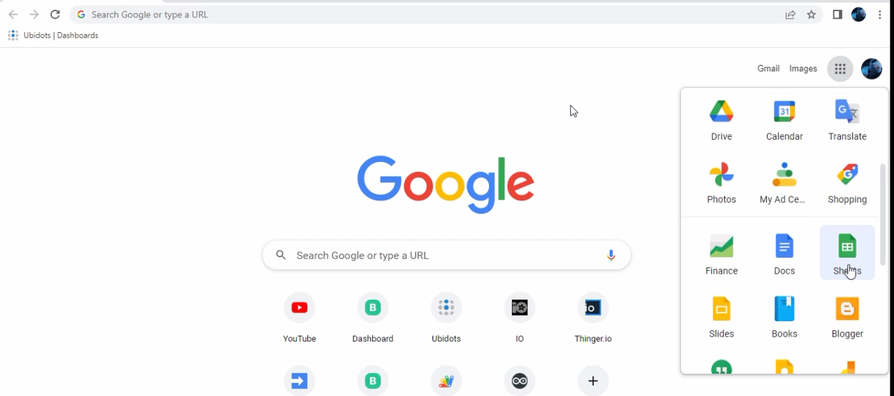
Click on the Google apps and click on the Sheet
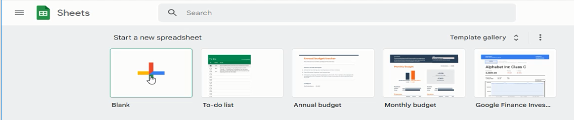
Then click on the blank sheet
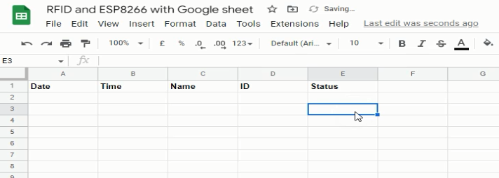
Then give a name to the sheet and enter the date, time, id, and status.
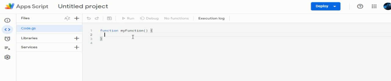
Click on the extension and click on the App Script
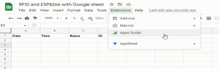
Then the App script will open
Paste the following code:
|
1 2 3 4 5 6 7 8 9 10 11 12 13 14 15 16 17 18 19 20 21 22 23 24 25 26 27 28 29 30 31 32 33 34 35 36 37 38 39 40 41 42 43 44 45 46 47 48 49 50 51 52 53 54 55 56 57 58 59 60 61 62 63 64 65 66 67 68 69 70 71 72 73 74 75 76 77 78 79 |
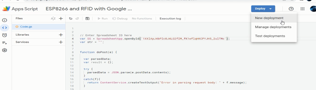
// Enter Spreadsheet ID here var SS = SpreadsheetApp.openById('1XFghoRmZzNLlYEkPPEEs1gjxM0aUsz_5HDJ58aQ_cKg'); var str = ""; function doPost(e) { var parsedData; var result = {}; try { parsedData = JSON.parse(e.postData.contents); } catch(f){ return ContentService.createTextOutput("Error in parsing request body: " + f.message); } if (parsedData !== undefined){ var flag = parsedData.format; if (flag === undefined){ flag = 0; } var sheet = SS.getSheetByName(parsedData.sheet_name); // sheet name to publish data to is specified in Arduino code var dataArr = parsedData.values.split(","); // creates an array of the values to publish var date_now = Utilities.formatDate(new Date(), "CST", "yyyy/MM/dd"); // gets the current date var time_now = Utilities.formatDate(new Date(), "CST", "hh:mm:ss a"); // gets the current time var value0 = dataArr [0]; // value0 from Arduino code var value1 = dataArr [1]; // value1 from Arduino code var value2 = dataArr [2]; // value2 from Arduino code // read and execute command from the "payload_base" string specified in Arduino code switch (parsedData.command) { case "insert_row": sheet.insertRows(2); // insert full row directly below header text //var range = sheet.getRange("A2:D2"); // use this to insert cells just above the existing data instead of inserting an entire row //range.insertCells(SpreadsheetApp.Dimension.ROWS); // use this to insert cells just above the existing data instead of inserting an entire row sheet.getRange('A2').setValue(date_now); // publish current date to cell A2 sheet.getRange('B2').setValue(time_now); // publish current time to cell B2 sheet.getRange('C2').setValue(value0); // publish value0 from Arduino code to cell C2 sheet.getRange('D2').setValue(value1); // publish value1 from Arduino code to cell D2 sheet.getRange('E2').setValue(value2); // publish value2 from Arduino code to cell E2 str = "Success"; // string to return back to Arduino serial console SpreadsheetApp.flush(); break; case "append_row": var publish_array = new Array(); // create a new array publish_array [0] = date_now; // add current date to position 0 in publish_array publish_array [1] = time_now; // add current time to position 1 in publish_array publish_array [2] = value0; // add value0 from Arduino code to position 2 in publish_array publish_array [3] = value1; // add value1 from Arduino code to position 3 in publish_array publish_array [4] = value2; // add value2 from Arduino code to position 4 in publish_array sheet.appendRow(publish_array); // publish data in publish_array after the last row of data in the sheet str = "Success"; // string to return back to Arduino serial console SpreadsheetApp.flush(); break; } return ContentService.createTextOutput(str); } // endif (parsedData !== undefined) else { return ContentService.createTextOutput("Error! Request body empty or in incorrect format."); } } |
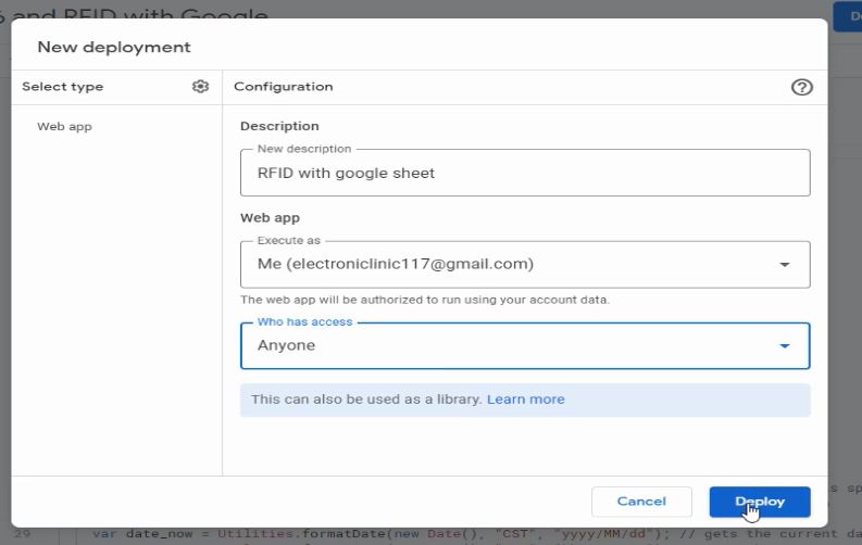
Then click on Deploy and click on the New Development
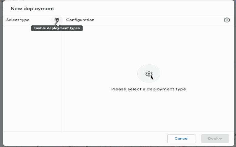
Then click on the enable deployment types.
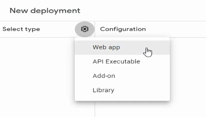
Now select deploy as web
Now select anyone and click on the deploy
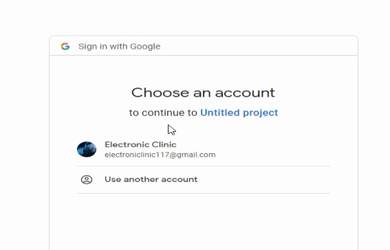
Now select the account in which you have created the Google sheet.
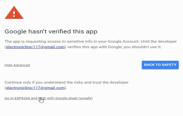
Now click on the go to ESP8266 and RFID with Google sheet unsafe
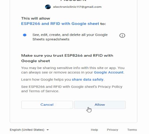
Now click on the allow button to give access to the account
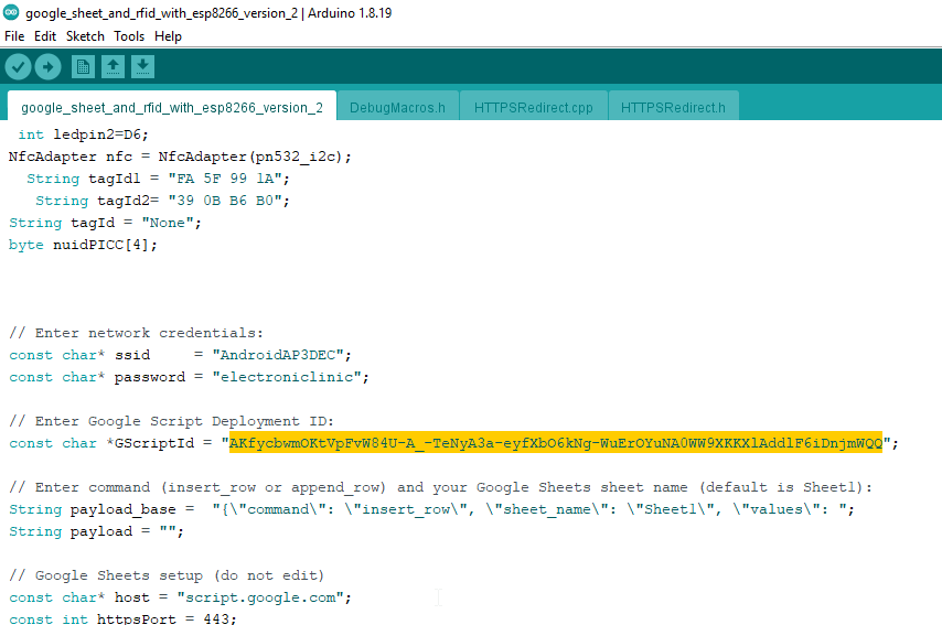
Then copy the deployment id
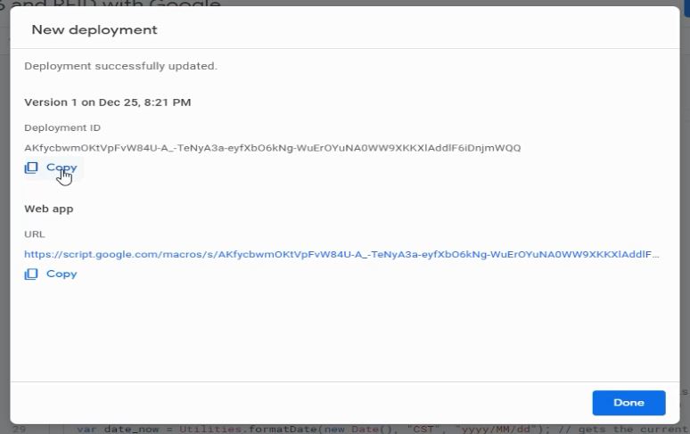
Paste the deployment id in the code
Project code:
|
1 2 3 4 5 6 7 8 9 10 11 12 13 14 15 16 17 18 19 20 21 22 23 24 25 26 27 28 29 30 31 32 33 34 35 36 37 38 39 40 41 42 43 44 45 46 47 48 49 50 51 52 53 54 55 56 57 58 59 60 61 62 63 64 65 66 67 68 69 70 71 72 73 74 75 76 77 78 79 80 81 82 83 84 85 86 87 88 89 90 91 92 93 94 95 96 97 98 99 100 101 102 103 104 105 106 107 108 109 110 111 112 113 114 115 116 117 118 119 120 121 122 123 124 125 126 127 128 129 130 131 132 133 134 135 136 137 138 139 140 141 142 143 144 145 146 147 148 149 150 151 152 153 154 155 156 157 158 159 160 161 162 163 164 165 166 167 168 169 170 171 172 173 174 175 176 177 178 179 180 181 182 183 184 185 186 187 188 189 190 191 192 193 194 195 196 197 198 199 200 201 202 203 204 205 206 207 208 209 210 211 212 213 214 215 216 217 218 219 220 221 222 223 224 225 226 227 228 229 230 231 232 233 234 235 236 237 238 239 240 241 242 243 244 245 246 247 248 |
#include <Adafruit_GFX.h> #include <Adafruit_SSD1306.h> #include <Arduino.h> #include <ESP8266WiFi.h> #include "HTTPSRedirect.h" #include <Wire.h> #include <PN532_I2C.h> #include <PN532.h> #include <NfcAdapter.h> PN532_I2C pn532_i2c(Wire); int ledpin1=D5; int ledpin2=D6; NfcAdapter nfc = NfcAdapter(pn532_i2c); String tagId1 = "FA 5F 99 1A"; String tagId2= "39 0B B6 B0"; String tagId = "None"; byte nuidPICC[4]; // Enter network credentials: const char* ssid = "AndroidAP3DEC"; const char* password = "electroniclinic"; // Enter Google Script Deployment ID: const char *GScriptId = "AKfycbwmOKtVpFvW84U-A_-TeNyA3a-eyfXbO6kNg-WuErOYuNA0WW9XKKXlAddlF6iDnjmWQQ"; // Enter command (insert_row or append_row) and your Google Sheets sheet name (default is Sheet1): String payload_base = "{\"command\": \"insert_row\", \"sheet_name\": \"Sheet1\", \"values\": "; String payload = ""; // Google Sheets setup (do not edit) const char* host = "script.google.com"; const int httpsPort = 443; const char* fingerprint = ""; String url = String("/macros/s/") + GScriptId + "/exec"; HTTPSRedirect* client = nullptr; // Declare variables that will be published to Google Sheets String user = ""; String id = ""; String enter =""; #define SCREEN_WIDTH 128 // OLED display width, in pixels #define SCREEN_HEIGHT 64 // OLED display height, in pixels // Declaration for an SSD1306 display connected to I2C (SDA, SCL pins) #define OLED_RESET -1 // Reset pin # (or -1 if sharing Arduino reset pin) Adafruit_SSD1306 display(SCREEN_WIDTH, SCREEN_HEIGHT, &Wire, OLED_RESET); void setup() { Serial.begin(9600); Serial.println('\n'); pinMode(ledpin1,OUTPUT); pinMode(ledpin2,OUTPUT); Serial.println("System initialized"); nfc.begin(); digitalWrite(ledpin1, LOW); digitalWrite(ledpin2, LOW); // Connect to WiFi WiFi.begin(ssid, password); Serial.print("Connecting to "); Serial.print(ssid); Serial.println(" ..."); while (WiFi.status() != WL_CONNECTED) { delay(1000); Serial.print("."); } Serial.println('\n'); Serial.println("Connection established!"); Serial.print("IP address:\t"); Serial.println(WiFi.localIP()); // Use HTTPSRedirect class to create a new TLS connection client = new HTTPSRedirect(httpsPort); client->setInsecure(); client->setPrintResponseBody(true); client->setContentTypeHeader("application/json"); Serial.print("Connecting to "); Serial.println(host); // Try to connect for a maximum of 5 times bool flag = false; for (int i=0; i<5; i++){ int retval = client->connect(host, httpsPort); if (retval == 1){ flag = true; Serial.println("Connected"); break; } else Serial.println("Connection failed. Retrying..."); } if (!flag){ Serial.print("Could not connect to server: "); Serial.println(host); return; } delete client; // delete HTTPSRedirect object client = nullptr; // delete HTTPSRedirect object display.begin(SSD1306_SWITCHCAPVCC, 0x3C); delay(2000); display.clearDisplay(); display.setTextColor(WHITE); delay(10); } void loop() { // create some fake data to publish display.clearDisplay(); display.setTextSize(2); display.setCursor(0, 10); display.print("Waiting..."); display.display(); readNFC(); display.clearDisplay(); display.setTextSize(2); display.setCursor(0, 10); display.print("Success"); display.display(); if(tagId==tagId1) { if( digitalRead(ledpin1) == 0) { digitalWrite(ledpin1, HIGH); user="Fahad"; id="123"; enter="in"; updatesheet(user,id, enter); tagId = ""; delay(1000); } } if(tagId==tagId1) { if( digitalRead(ledpin1) == 1) { digitalWrite(ledpin1, LOW); enter=""; user="Fahad"; id="123"; enter="out"; updatesheet(user,id, enter); tagId = ""; delay(1000); } } if(tagId==tagId2) { if( digitalRead(ledpin2) == 0) { digitalWrite(ledpin2, HIGH); user=""; id=""; enter=""; user="Fawad"; id="456"; enter="in"; updatesheet(user,id, enter); tagId = ""; delay(1000); } } if(tagId==tagId2) { if( digitalRead(ledpin2) == 1) { digitalWrite(ledpin2, LOW); user="Fawad"; id="456"; enter="out"; updatesheet(user,id, enter); tagId = ""; delay(1000); } } } void updatesheet(String user, String id, String enter) { static bool flag = false; if (!flag){ client = new HTTPSRedirect(httpsPort); client->setInsecure(); flag = true; client->setPrintResponseBody(true); client->setContentTypeHeader("application/json"); } if (client != nullptr){ if (!client->connected()){ client->connect(host, httpsPort); } } else{ Serial.println("Error creating client object!"); } // Create json object string to send to Google Sheets payload = payload_base + "\"" + user + "," + id + "," + enter + "\"}"; // Publish data to Google Sheets Serial.println("Publishing data..."); Serial.println(payload); if(client->POST(url, host, payload)){ // do stuff here if publish was successful } else{ // do stuff here if publish was not successful Serial.println("Error while connecting"); } // a delay of several seconds is required before publishing again delay(5000); } void readNFC() { if (nfc.tagPresent()) { NfcTag tag = nfc.read(); tag.print(); tagId = tag.getUidString(); Serial.println("Tag id"); Serial.println(tagId); } delay(1000); } |
The Google sheet setup is completed and finally, you can click on the Upload button.
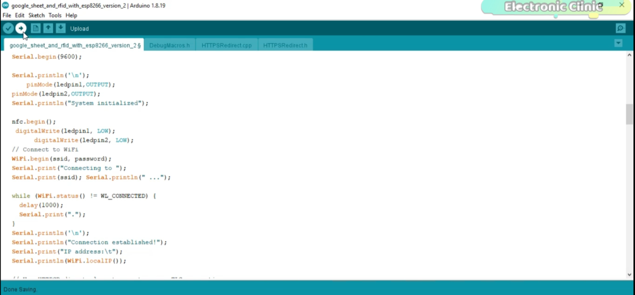
Make sure you keep the main programming file and all the header files in the same folder. For the Nodemcu ESP8266 WiFi board installation and libraries installation, you can read my getting started articles on the Google spreadsheet, PN532 RFID module, and SSD1306 Oled Display Module.
After uploading the code, next I opened the Serial Monitor and started to swipe the RFID tags in order to find the Tag ids. Right now I am using only two RFID tags.
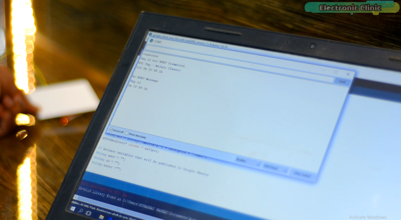
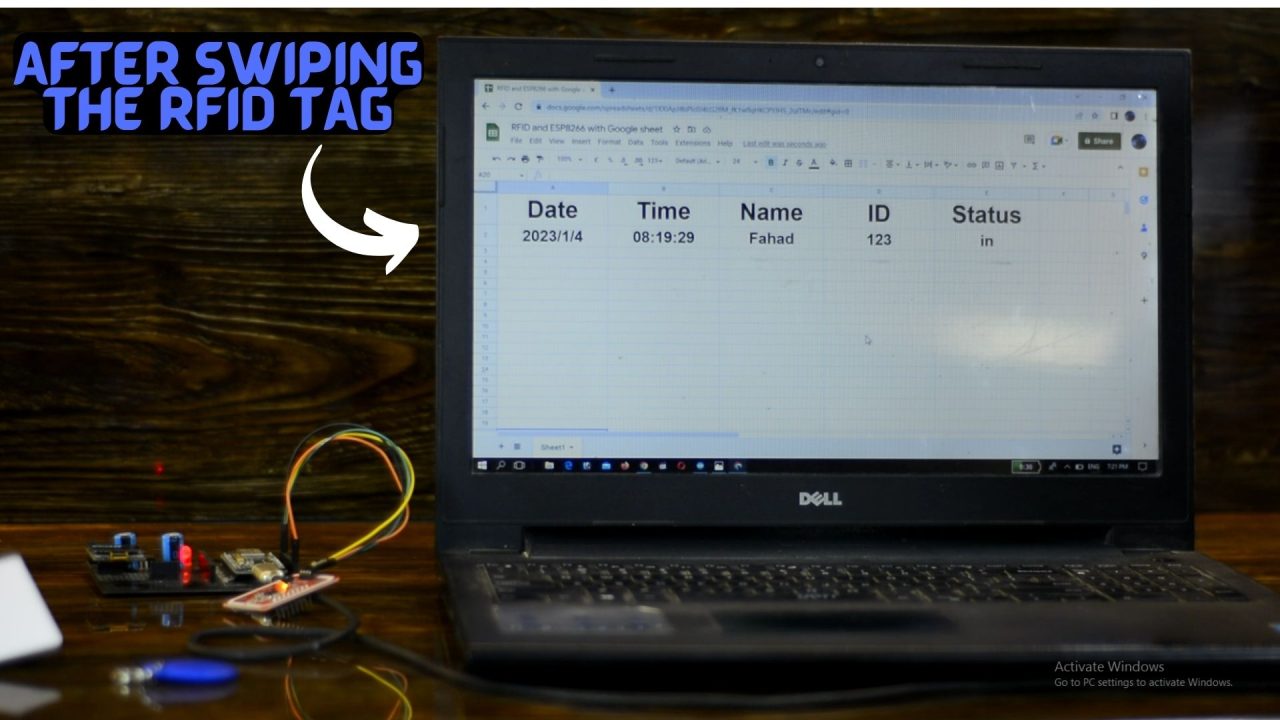
Anyway, I added both the Tag ids in the programming and again uploaded the program. I came back to Google Spreadsheet in order to check if I can receive the Date, Time, Name, ID, and Status.
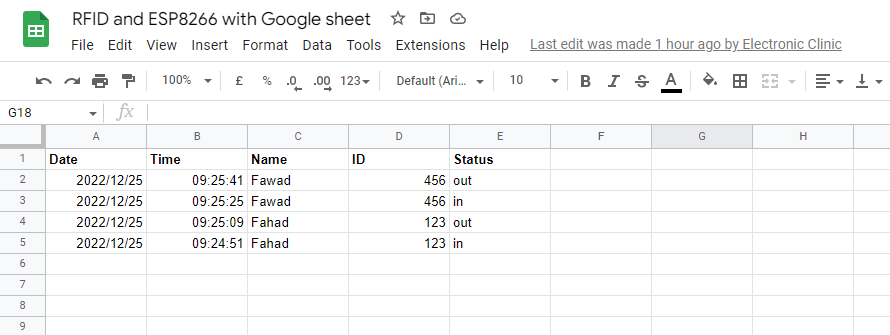
As soon as I swiped the RFID Tag I received the data. So, this is how easily you can send anything from Nodemcu ESP8266 to Google Spreadsheet from any part of the world. So, that’s all for now.
Watch the Video Tutorial:

Discover more from Electronic Clinic
Subscribe to get the latest posts sent to your email.

Hi great article.
I always wonder something about these projects and perhaps you could shed some light.
What happens if the power gets interupted or the wifi connection gets disrupted inbetween the time the card is swiped and sent?
Is there perhaps a different and more reliable approach to using google sheets and insuring for 100% certain that the data is logged and did indeed reach the spreadsheet.
I had a similar project with a load cell and out of say 25 “send data” the spreadhseet only registered say 24 for example which kind of makes the whole project unreliable.
I would love to know your thoughts and opinion on this. I love your website and the way you explain everything.
Hi, I tried the code, but I keep getting the following error in the serial monitor:
System initialized
Didn’t find PN53x board
Does anyone know how to solve it?
No i have the same, I have mine in HSU mode, i tried many different combinations of pin connections following everything people online have said but nothing works for me so far with nodemcu. I soldered the wires at 90 degree angle on the pn532, i have no idea what to do now.
Shahzada, thank you for the excellent, well documented, example! Although I don’t have an immediate need for the Excel integration, it’s nice to see how it could be done. You solved my problem of the PB532 not working with my ESP8266 – I forgot the SSD1306 and the PN532 share the I2C. Adding the 0x3C address to the SSD1306 solved it!
My use of the PN532 with the ESP8266 is to allow my users to use a tool like NFC Tools and store their WiFi SSID and password, then they can use my product in their network, without me having to provide a soft keyboard.