PN532 RFID NFC Module with Arduino, How to use HSU UART, SPI, & I2C
Last Updated on May 10, 2026 by Engr. Shahzada Fahad
Table of Contents
PN532 RFID NFC Module:
PN532 RFID NFC Module with Arduino, how to use HSU UART, SPI, & I2C-in today’s tutorial, I am going to use the PN532 NFC RFID module with Arduino. Since this is a getting started article on the PN532 RFID module; so I will try my level best to explain as much as possible. I will also try to make this article as simple and easy to understand as possible. If you have any questions or suggestions, feel free to comment below. I will try to answer all your questions as soon as possible.
Anyway, I will also compare the PN532 RFID module with the most popular and well-known RFID module MFRC522. I will also try to explain the difference between PN532 and MFRC522. I will also share with you the technical specifications of PN532 so that you can decide which one is the right RFID module for you. And in the end,I will explain how to interface the PN532 RFID module with the Arduino and how to write basic programs to control an LED using different modes UART, I2C, and SPI. So, without any further delay let’s get started!!!
Amazon Links:
Arduino Nano USB-C Type (Recommended)
*Disclosure: These are affiliate links. As an Amazon Associate I earn from qualifying purchases.
PN532 RFID Vs MFRC522 RFID Module:
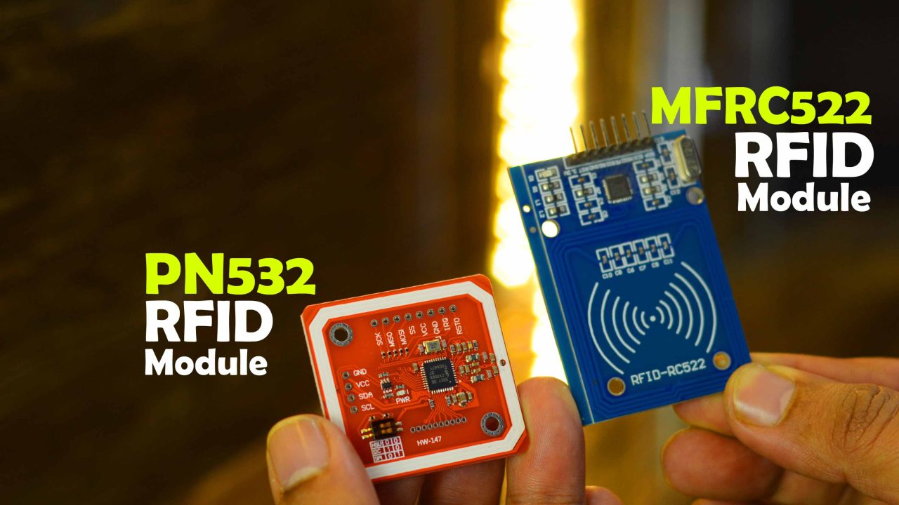
First, let’s compare the PN532 RFID module with the most well-known MFRC522 RFID Module which I have been using for quite a long time.
MFRC522 RFID Module:
The MFRC522 RFID Module is a good choice if you’re looking for an inexpensive RFID reader module that supports the MIFARE® Classic 1k and 4k chips. You can read tags at up to 5m (16ft) with an active antenna and 10cm (3.9in) with a passive one. It has a high-speed SPI interface, which makes it easy to use in embedded applications. I have used it in so many projects “MFRC522 RFID Based Projects”.
PN532 RFID Module:
While on the other hand, the PN532 NFC RFID Module V3 is a very powerful and flexible RFID module. It can be used for many different applications such as access control, time attendance systems, animal identification, inventory management, and more.
It uses less power than the MFRC522 because its parts are designed for low-power consumption and it is also more flexible than the MFRC522. It has additional features such as support for a wider range of frequencies, making it easier to read tags from more angles without having to move your antenna around.
It is compatible with all ISO 14443 A and B standards, as well as the NXP’s MIFARE® Classic 1k and 4k chips. The PN532 has a high-speed SPI interface and is firmware upgradeable via an AT command set. It can read tags at up to 8m (27ft) with an active antenna and 10cm (3.9in) with a passive one. You can even use the PN532 in Linux or Mac OS X thanks to its open source drivers!

The PN532 also has an I2C interface, HSU “High Speed UART”, and SPI, which makes it easy to use in embedded applications. So, If you’re looking for a more advanced RFID reader module, the PN532 is a good choice.It can pretty much do it all, such as read and write to tags and cards, communicate with phones (say for payment processing), and ‘act’ like an NFC tag. If you want to do any sort of embedded NFC work, this is the chip you’ll want to use!
PN532 Technical Specifications:
It supports a Wide Range of input voltages from 2.7 to 3.6 volts. And this means it can be used with all 3.3V and 5V compatible controller boards like Arduino, ESP32, ESP8266, Raspberry Pi, Raspberry Pi Pico, STM32, and so on.In Active mode it uses 50mA at 13.56Mhz and 80mA at 125kHz.
While in sleep mode it uses only 1uA.
Now, let’s go ahead and take a look at its pinout.
- Voltage: 2.7V to 5.5V DC
- Current consumption (active): 50mA @ 13.56MHz, 80mA @ 125 kHz
- Current consumption (sleep): 1uA
- Operating frequency: 125KHz, 13.56MHz
- Communication protocol: ISO 14443A/B, ISO 15693 (NFC Forum Type 2)
- Antenna interface: U.FL connector or PCB trace antenna
- RF output power: -13dBm (10 mW) @ 13.56MHz, -9dBm (1 mW) @ 125 kHz
- Operating temperature range: -40°C to +85°C
- Typical operating distance in Reader/Writer mode for communication to ISO/IEC 14443A/MIFARE®, ISO/IEC 14443B or FeliCa cards up to 50 mm depending on antenna size and tuning.
- operating distance in NFCIP-1 mode up to 50 mm depending on antenna size, tuning and power supply
- Typical operating distance in ISO/IEC 14443A/MIFARE or FeliCa card emulation mode of approximately 100 mm depending on antenna size, tuning and external field strength
- Supports MIFARE Classic® 1K or MIFARE Classic 4K encryption in Reader/Writer mode and MIFARE higher transfer speed communication at 212 kbit/s and 424 kbit/s
- Supports contactless communication according to the FeliCa protocol at 212 kbit/s and 424 kbit/s
- Integrated RF interface for NFCIP-1 up to 424 kbit/s
- Possibility to communicate on the RF interface above 424 kbit/s using external analog components
- Supported host interfaces
- SPI interface
- I²C interface
- High-speed UART
- Low power modes
- Dedicated host interrupts
- Hard-Power-Down mode (1 µA typical)
- Soft-Power-Down mode (22 µA typical)
- Automatic wake-up on I²C, HSU and SPI interfaces when device is in Power-down mode
- Programmable timers
- Crystal oscillator
- Power switch for external secure companion chi
- Dedicated IO ports for external device control
- Integrated antenna detector for production test
- ECMA 373 NFC-WI interface to connect an external secure IC
The PN532 uses about 50mA of current. To calculate the voltage drop over your antenna, you can use Ohm’s law: V = I × R Where “V” is voltage drop, “I” is current and “R” is resistance. So for example if you have a 1 meter long wire with a resistance of 0.3 ohms and it’s carrying 50mA of current then the voltage drop will be 0.15V (0.5mA x 0.3 ohms). The PN532 is a 3.3V device. It can draw up to 20mA of current at 3.6V and up to 50mA at 2.7-3.6V, which is sufficient for transmitting data from a few meters away (depending on the RFID tag).
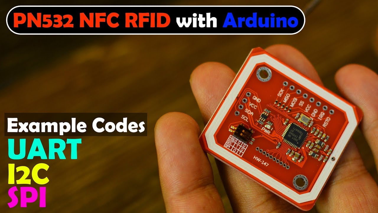
PN532 RFID Module V3 Pinout:
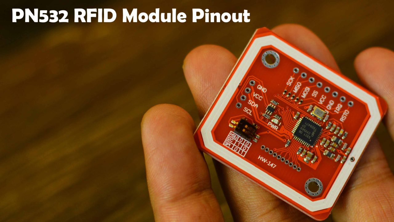
You can see all the headers are clearly labeled. The PN532 NFC RFID Module V3 can be interfaced with the Arduino and other controller boards using HSU (High Speed UART), I2C, and SPI.

This board has an onboard level shifter, standard 5V TTL for I2C and UART, and 3.3V TTL SPI. Anyway, the I2C and HSU (High Speed UART) shares the same pins.

The HSU mode is configured as the default mode. But if you want to change the interface then you can use these toggle switches. Don’t worry I will explain how to use all the three modes. First I will start with its default mode HSU.
PN532 RFID UART Circuit Diagram:
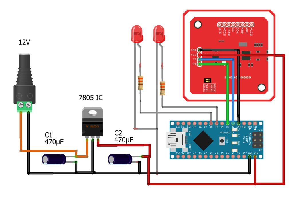
The VCC and GND pins of the PN532 RFID module are connected with the Arduino 5V and GND pins. While the TX and RX pins are connected with the Arduino D2 and D3 pins.
Two LEDs are connected with the Arduino pins 5 and 6. These are the minimal connections that you will need to get started. If you want to externally power up your Arduino board then you can use this 5V regulated power supply based on the LM7805 Voltage regulator. Otherwise, you can use your laptop to power up the Arduino.

As usual, I am using my Arduino Nano development board. I have connected the LEDs and PN532 RFID module as per the circuit diagram.For the HSU High Speed UART, you don’t need to change the position of the toggle switches, as by default it’s set to UART Mode.
It doesn’t matter if you start with HSU, I2C, or SPI, first you will need to download all the required libraries.
Download PN532 RFID Module Library
Simply download the above WinRAR folder, extract it, and double-click to open the folder.

You can see inside this folder we have all the required libraries, so simply copy these folders and paste it into the Arduino libraries folder.
PN532 RFID UART Programming:
|
1 2 3 4 5 6 7 8 9 10 11 12 13 14 15 16 17 18 19 20 21 22 23 24 25 26 27 28 29 30 31 32 33 34 35 36 37 38 39 40 41 42 43 44 45 46 47 48 49 50 51 52 53 54 55 56 57 58 59 60 61 62 63 64 65 66 67 68 69 70 71 72 73 74 75 76 77 78 79 80 81 82 83 84 85 86 87 88 89 90 91 92 93 94 95 96 97 98 99 100 101 102 103 104 105 106 107 108 109 110 111 112 113 114 115 116 117 118 119 120 121 122 123 124 125 126 127 128 129 130 131 132 133 134 135 136 137 |
#include <SoftwareSerial.h> #include <PN532_SWHSU.h> #include <PN532.h> SoftwareSerial SWSerial( 3, 2 ); // RX, TX //RX pin with D3 and TX pin with D2 int ledpin1=5; int ledpin2=6; PN532_SWHSU pn532swhsu( SWSerial ); PN532 nfc( pn532swhsu ); String tagId = "None", dispTag = "None"; byte nuidPICC[4]; String tagId1 = "57.11.182.176"; String tagId2= "250.95.153.26"; void setup(void) { Serial.begin(115200); pinMode(ledpin1,OUTPUT); pinMode(ledpin2,OUTPUT); Serial.println("Hello Maker!"); // Serial2.begin(115200, SERIAL_8N1, RXD2, TXD2); nfc.begin(); uint32_t versiondata = nfc.getFirmwareVersion(); if (! versiondata) { Serial.print("Didn't Find PN53x Module"); while (1); // Halt } // Got valid data, print it out! Serial.print("Found chip PN5"); Serial.println((versiondata >> 24) & 0xFF, HEX); Serial.print("Firmware ver. "); Serial.print((versiondata >> 16) & 0xFF, DEC); Serial.print('.'); Serial.println((versiondata >> 8) & 0xFF, DEC); // Configure board to read RFID tags nfc.SAMConfig(); //Serial.println("Waiting for an ISO14443A Card ..."); digitalWrite(ledpin1, LOW); digitalWrite(ledpin2, LOW); } void loop() { readNFC(); if(tagId==tagId1) { if( digitalRead(ledpin1) == 0) { digitalWrite(ledpin1, HIGH); tagId = ""; delay(1000); } } if(tagId==tagId1) { if( digitalRead(ledpin1) == 1) { digitalWrite(ledpin1, LOW); tagId = ""; delay(1000); } } if(tagId==tagId2) { if( digitalRead(ledpin2) == 0) { digitalWrite(ledpin2, HIGH); tagId = ""; delay(1000); } } if(tagId==tagId2) { if( digitalRead(ledpin2) == 1) { digitalWrite(ledpin2, LOW); tagId = ""; delay(1000); } } } void readNFC() { boolean success; uint8_t uid[] = { 0, 0, 0, 0, 0, 0, 0 }; // Buffer to store the returned UID uint8_t uidLength; // Length of the UID (4 or 7 bytes depending on ISO14443A card type) success = nfc.readPassiveTargetID(PN532_MIFARE_ISO14443A, &uid[0], &uidLength); if (success) { Serial.print("UID Length: "); Serial.print(uidLength, DEC); Serial.println(" bytes"); Serial.print("UID Value: "); for (uint8_t i = 0; i < uidLength; i++) { nuidPICC[i] = uid[i]; Serial.print(" "); Serial.print(uid[i], DEC); } Serial.println(); tagId = tagToString(nuidPICC); dispTag = tagId; Serial.print(F("tagId is : ")); Serial.println(tagId); Serial.println(""); delay(1000); // 1 second halt } else { // PN532 probably timed out waiting for a card Serial.println("Timed out! Waiting for a card..."); } } String tagToString(byte id[4]) { String tagId = ""; for (byte i = 0; i < 4; i++) { if (i < 3) tagId += String(id[i]) + "."; else tagId += String(id[i]); } return tagId; } |
This code is written for the HSU Mode and you can see I am using pins 3 and 2. And the LEDs are connected with the Arduino Pins 5 and 6. You can also use this code to find the RFID Tags IDs. For this simply Open the Serial monitor and start scanning your RFID Tags.

In a similar way, I also found the UID of the card.
String tagId1 = “57.11.182.176”;
String tagId2= “250.95.153.26”;
Using these IDs in the programming you can control certain things, in my case I am going to control 2 LEDs. Anyway, I have already uploaded this program and let’s watch the PN532 RFID module HSU mode in action.

Now, using the RFID Key Chain Tag.

For the practical demonstration, watch video tutorial on my YouTube channel “Electronic Clinic”. Now, let’s go ahead and start with the I2C mode.
PN532 RFID I2C Circuit Diagram:
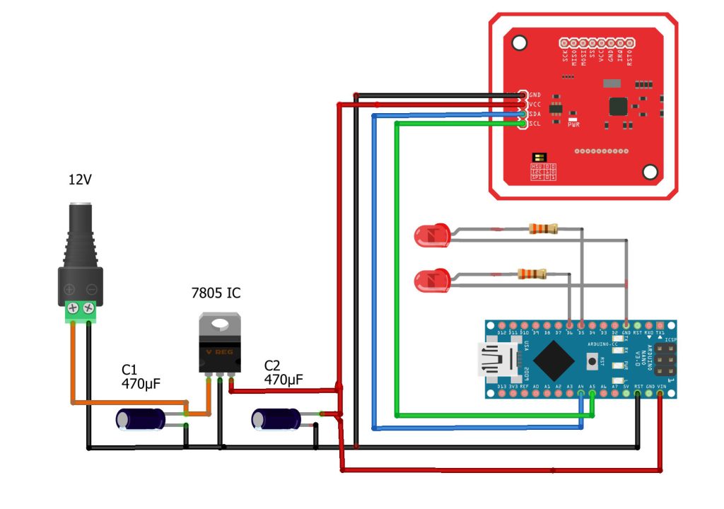
I have already explained that HSU and I2C shares the same pins. This time you can see, the SDA and SCL pins of the PN532 RFID module are connected with the Arduino A4 and A5 pins. While everything else remains exactly the same.

Now, you can see the SDA and SCL pins are connected with the Arduino A4 and A5 pins. Since this time I am using the I2C mode, so I have turned ON the channel 1.
PN532 RFID I2C Programming:
|
1 2 3 4 5 6 7 8 9 10 11 12 13 14 15 16 17 18 19 20 21 22 23 24 25 26 27 28 29 30 31 32 33 34 35 36 37 38 39 40 41 42 43 44 45 46 47 48 49 50 51 52 53 54 55 56 57 58 59 60 61 62 63 64 65 66 67 68 69 70 71 72 73 74 75 76 77 78 79 80 81 82 83 84 85 86 |
// for I2C Communication #include <Wire.h> #include <PN532_I2C.h> #include <PN532.h> #include <NfcAdapter.h> PN532_I2C pn532_i2c(Wire); int ledpin1=5; int ledpin2=6; NfcAdapter nfc = NfcAdapter(pn532_i2c); String tagId1 = "FA 5F 99 1A"; String tagId2= "39 0B B6 B0"; String tagId = "None"; byte nuidPICC[4]; void setup(void) { Serial.begin(115200); pinMode(ledpin1,OUTPUT); pinMode(ledpin2,OUTPUT); Serial.println("System initialized"); nfc.begin(); digitalWrite(ledpin1, LOW); digitalWrite(ledpin2, LOW); } void loop() { readNFC(); if(tagId==tagId1) { if( digitalRead(ledpin1) == 0) { digitalWrite(ledpin1, HIGH); tagId = ""; delay(1000); } } if(tagId==tagId1) { if( digitalRead(ledpin1) == 1) { digitalWrite(ledpin1, LOW); tagId = ""; delay(1000); } } if(tagId==tagId2) { if( digitalRead(ledpin2) == 0) { digitalWrite(ledpin2, HIGH); tagId = ""; delay(1000); } } if(tagId==tagId2) { if( digitalRead(ledpin2) == 1) { digitalWrite(ledpin2, LOW); tagId = ""; delay(1000); } } } void readNFC() { if (nfc.tagPresent()) { NfcTag tag = nfc.read(); tag.print(); tagId = tag.getUidString(); Serial.println("Tag id"); Serial.println(tagId); } delay(1000); } |
This time I included the I2C library. I have already uploaded this program and now let’s watch the PN532 RFID Module I2C mode in action.

I successfully controlled the two LEDs using the RFID Card and the RFID key chain tag.Now, let’s go ahead and start with the SPI mode.
PN532 RFID SPI Circuit Diagram:
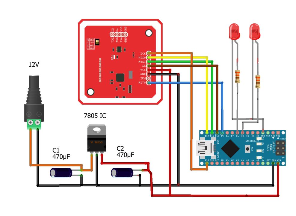
If you want to use the SPI mode of the PN532 RFID module then you will need to connect SCK with the Arduino pin 13, MISO with pin 12, MOSI with pin 11, SS with Pin 10, RST0 with Pin 9 of the Arduino. While everything else remains exactly the same.I connected the PN532 RFID module SPI pins with the Arduino as per the circuit diagram.

Now, to activate the SPI mode on the PN532 RFID module you will need to turn OFF the channel 1 and turn ON the channel 2.
PN532 RFID SPI Programming:
|
1 2 3 4 5 6 7 8 9 10 11 12 13 14 15 16 17 18 19 20 21 22 23 24 25 26 27 28 29 30 31 32 33 34 35 36 37 38 39 40 41 42 43 44 45 46 47 48 49 50 51 52 53 54 55 56 57 58 59 60 61 62 63 64 65 66 67 68 69 70 71 72 73 74 75 76 77 78 79 80 81 82 |
// for SPI Communication #include <SPI.h> #include <PN532_SPI.h> #include <PN532.h> #include <NfcAdapter.h> PN532_SPI interface(SPI, 10); // create a PN532 SPI interface with the SPI CS terminal located at digital pin 10 NfcAdapter nfc = NfcAdapter(interface); // create an NFC adapter object String tagId = "None"; String tagId1 = "FA 5F 99 1A"; String tagId2= "39 0B B6 B0"; int ledpin1=5; int ledpin2=6; void setup(void) { Serial.begin(115200); Serial.println("System initialized"); pinMode(ledpin1,OUTPUT); pinMode(ledpin2,OUTPUT); nfc.begin(); } void loop() { readNFC(); if(tagId==tagId1) { if( digitalRead(ledpin1) == 0) { digitalWrite(ledpin1, HIGH); tagId = ""; delay(1000); } } if(tagId==tagId1) { if( digitalRead(ledpin1) == 1) { digitalWrite(ledpin1, LOW); tagId = ""; delay(1000); } } if(tagId==tagId2) { if( digitalRead(ledpin2) == 0) { digitalWrite(ledpin2, HIGH); tagId = ""; delay(1000); } } if(tagId==tagId2) { if( digitalRead(ledpin2) == 1) { digitalWrite(ledpin2, LOW); tagId = ""; delay(1000); } } } void readNFC() { if (nfc.tagPresent()) { NfcTag tag = nfc.read(); tag.print(); tagId = tag.getUidString(); } delay(1000); } |
This time you can see I have added the SPI library. Everything else remains exactly the same. I have already uploaded this program and now let’s watch PN532 RFID Module SPI mode in action.

I successfully controlled the two LEDs using RFID Key Chain Tag and the RFID Card tag. So, that’s all about how to use the PN532 NFC RFID module with the Arduino and how to use all the three interfaces or modes UART, I2C, and SPI.
In my upcoming tutorial, I will use the same PN532 RFID module with the Nodemcu ESP8266 and Google Spreadsheet. This will be a fun project, so subscribe to my Website and YouTube channel if you don’t want to miss any of my upcoming articles and videos.
Watch Video Tutorial:
Discover more from Electronic Clinic
Subscribe to get the latest posts sent to your email.


Hello, thank you so much for this guide, after a few tweaks i was able to get this working on stm32 bluepill on stm32cubeide. Now I am trying to figure out to modify the tag keys, A and B for security of the content i will be writing to the tag. Any help will be really appreciated
How did you do it?
You wrote that it can read 125kHz and alo 13,56MHz tags. I found that it can reda just 13,56MHz.
Hello. Thanks for this tutorial. Can you explain how to retrieve user-writeable fields?
Thanks.