Invisible Security System using Microwaves Sensor and Sinric Pro, Unbreakable
Table of Contents
Invisible Security System:
Invisible Security System using ESP8266, DFRobot Gravity Digital Microwave Sensor, and Sinric Pro IoT Mobile Application-I am sure you might have seen the best security systems in real life and in movies, but the Security system that I have designed for you guys is going to blow your mind as it’s completely invisible. If you are thinking about lasers and hidden cameras then you are absolutely wrong because those are detectable.
My invisible security system is not physically visible, it can be inside a wall, or it may be inside drawers, or maybe inside a cupboard. So, how anyone can break such a security system that’s not physically visible, undetectable by infrared glasses, night vision cameras, etc. So, this makes my designed security system unbreakable.
Anyway,I installed my invisible security system in the workshop. And I asked my brother and cousins to go and steal something from my workshop without being detected by the security system. I used my cell phone application to activate the Security system.
Just with a single click I can enable and disable my invisible security system. Now, this is a very powerful feature, I don’t have to physically approach the security system in order to enable it or disable it.They tried multiple times and tried different techniques but they were unable to break the Invisible security system.
Each time they entered the workshop, my designed invisible security system immediately detected them.
“For practical demonstration watch my video available on my YouTube channel Electronic Clinic”.
Anyway, I disabled my Invisible security system using my cell phone and I told them to search for it. As expected they searched all the drawers, they looked for it behind the curtains, and they even researched for it behind the TV. They were also looking for any holes, I guess they might have been expecting something similar to a PIR Sensor, or Infrared sensor, or Ultrasonic Sensor, etc. I have no idea what they have been thinking about.
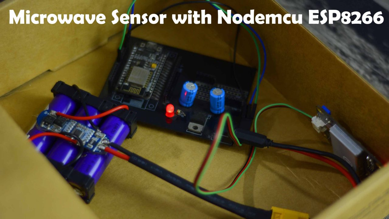
Anyway, the time they were searching for the security system. They completely ignored this box, and you won’t believe!it’s inside this box.
You can see there are no holes. The sensor that I have used for building this invisible security system uses Microwaves and you know microwaves can penetrate through walls, wood sheets, cardboard sheets etc. Instead of keeping this security system inside this box, I can fix it anywhere. Let me open this box and explain how I build this invisible security system.
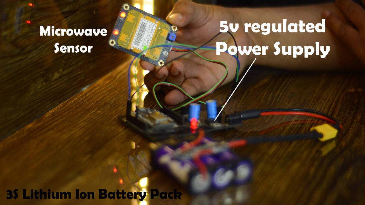
I am using my designed 3S Lithium Ion battery pack for powering the Nodemcu ESP8266 Development board.
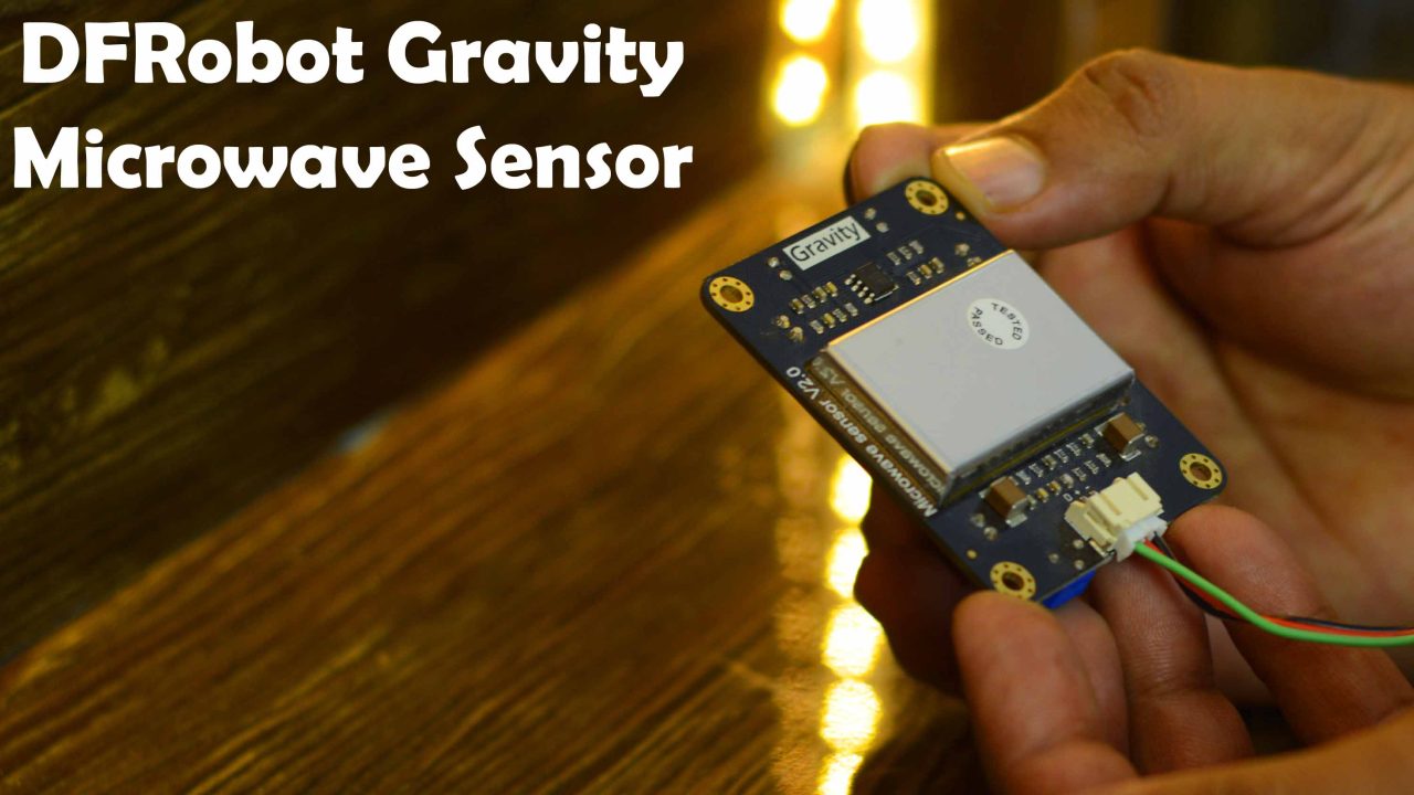
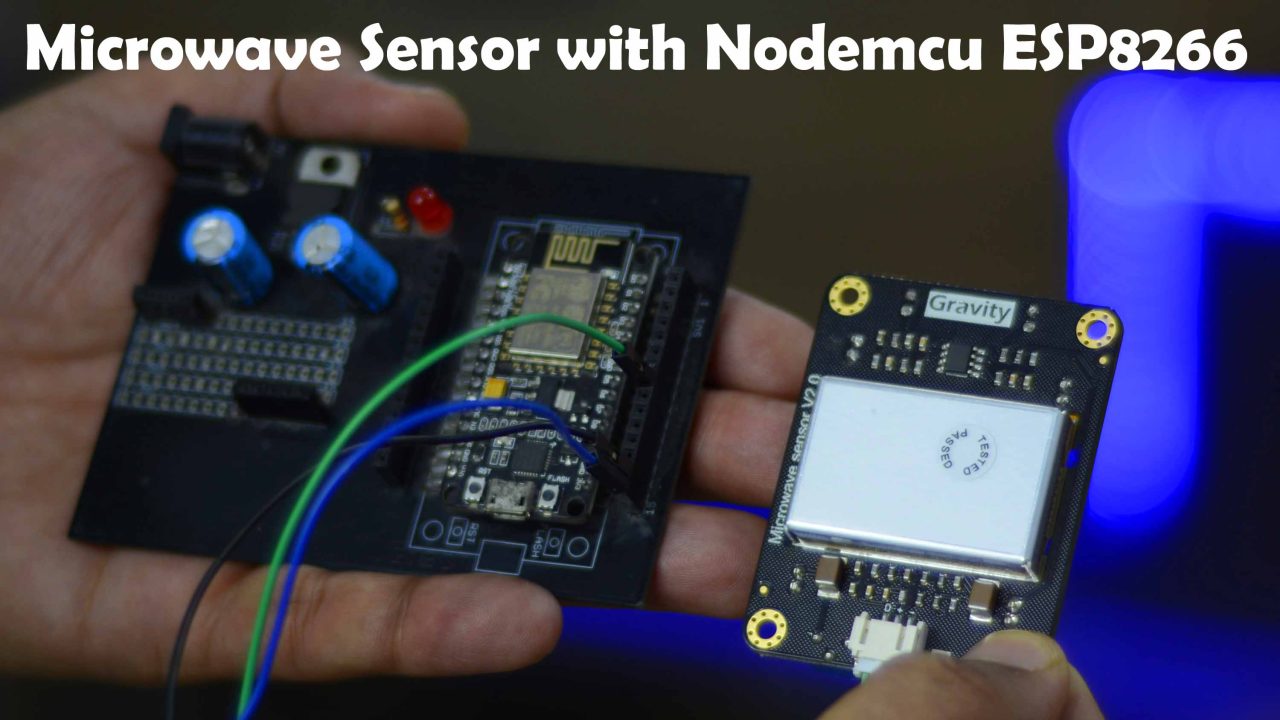
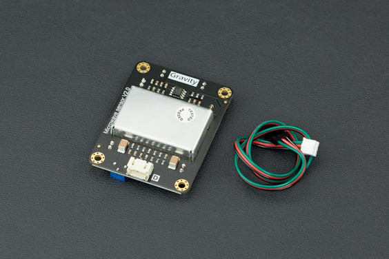
I am using the Gravity Digital Microwave Sensor V2.0 from the Dfrobot. This microwave sensor is able to detect objects without physical contact. It’s readings are not affected by temperature, humidity, noise, air, dust, or light which makes it suitable for harsh environments. This sensor also has strong resistance to radio frequency interference. Due to its low output, it’s not harmful to the human body. Since this sensor uses microwaves and you know microwaves have a wide detection range and velocity equal to the speed of light. This digital microwave sensor also supports non-life-class object detection. I have already used it with Arduino; so, for more technical specifications and basic things you can read my article on Arduino and digital Microwave sensor.
This time round I am using this Digital Microwave Sensor with ESP8266 WiFi module and I am using the Sinric Pro Cell phone application for monitoring. So, basically, it is an IoT-based Invisible security system. And by the way, if you have never used the Sinric Pro IoT platform then I highly recommend read my getting started article on the Sinric Pro IoT Platform.
Altium Designer + Altium 365 + Octopart:
Altium 365 lets you hold the fastest design reviews ever. Share your designs from anywhere and with anyone with a single click. it’s easy, leave a comment tagging your teammate and they’ll instantly receive an email with a link to the design. Anyone you invite can open the design using a web browser. Using the browser interface, you’re able to comment, markup, cross probe, inspect, and more. Comments are attached directly to the project, making them viewable within Altium designer as well as through the browser interface. Design, share, and manufacture, all in the same space with nothing extra to install or configure. Connect to the platform directly from Altium Designer without changing how you already design electronics. Altium 365 requires no additional licenses and comes included with your subscription plan.
Get real-time component insights as you design with Octopart built into Altium 365. Octopart is the fastest search engine for electronic parts and gives you the most up-to-date part data like specs, datasheets, cad models, and how much the part costs at different amounts etc. Right in the design environment so you can focus on your designs. Start with Altium Designer and Activate Altium 365. Search for electronic parts on Octopart.
Amazon Links:
DFRobot Gravity Digital Microwave Sensor
Other Tools and Components:
Super Starter kit for Beginners
PCB small portable drill machines
*Please Note: These are affiliate links. I may make a commission if you buy the components through these links. I would appreciate your support in this way!
Gravity Digital Microwave sensor:
The microwave sensor applies the Doppler effect to detect moving objects using microwaves. This differs from the method used by a regular infrared (IR) sensor as microwave is sensitive to a variety of objects that are microwave-reflective, and its sensor readings are not affected by the ambient temperature.
This type of microwave sensor is widely used in industrial, transportation, and civil applications such as measuring vehicle speed, liquid levels, automatic door motion detection, automatic washing, production line material detection and car reversing sensors, etc.
The microwave detection method has the following advantages compared to other methods:
- Non-contact detection
- Readings not affected by temperature, humidity, noise, air, dust or light – suitable for harsh environments
- Strong resistance to radio frequency interference
- Low output, unharmful to human
- Wide detection range and high velocity
- Supports non-living object detection
APPLICATIONS
The microwave sensor can be useful together with other sensors to enhance its measurement accuracy. For example, Microwave sensor could decrease the pseudo fault report rate of human motion detection. And it does a good job in safety & security work
SPECIFICATION
- Working Voltage: 5V + 0.25V
- Working Current (CW): 60mA max., 37mA typical
- Interface: Gravity 3-Pin interface(Digital)
- Size: 48.5x63mm
- Emission parameters:
- Detection Distance: 2-16M continuously adjustable
- Emission Frequency: 10.525 GHz
- Precision Frequency Setting: 3MHz
- Output Power (minimum): 13dBm EIRP
- Harmonic Emission: < -10dBm
- Average Current (5%DC): 2mA typ.
- Pulse Width (Min.): 5uSec
- Load Cycle (Min.): 1%
- Reception Parameters:
- Sensitivity:(10dB S/N ratio) 3Hz to 80Hz
- Bandwidth: -86dBm
- 3Hz to 80Hz Bandwidth Clutter: 10uV
- Antenna Gain: 8dBi
- Vertical 3dB Beam Width: 36 degrees
- Level 3dB Beam Width: 72 degrees
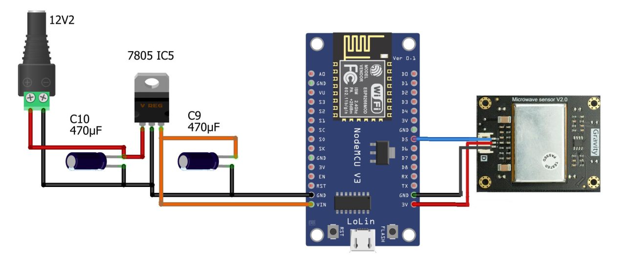
Now, let’s take a look at the circuit diagram.
Invisible Security System, Circuit Diagram:
The circuit diagram is very simple. You can see the Output of the Microwave sensor is connected to the digital Pin D5 of the Nodemcu ESP8266 WiFi module. While the +5v and GND pins are connected to the ESP8266 3.3v and GND pins.
On the top left side is the regulated 5V power supply based on the LM7805 voltage regulator. J1 is the DC female power jack and this is where we connect a 12v adaptor or a battery. If you want to use a 3.7V lithium Ion battery or 3.7V Lipo battery then there is no need to add this 5V power supply.
The reason, I have added this 5V regulated power supply is that; this is a development board and I use it for testing my ESP8266-based projects and mostly I use 12V adaptors or my designed 4S and 3S Lithium Ion Battery packs. I have got plenty of these battery packs. So, for the demonstration purposes I am going to use 3S lithium Ion Battery Pack. If want to make the same 3S and 4S lithium Ion batteries packs then you can read my article on how to make 3S and 4S lithium Ion Battery Packs.
Download ESP8266 PCB Gerber Files:
Anyway, I connected my Digital Microwave sensor as per the circuit diagram and now let’s start with the Sinric Pro setup.
Sinric Pro Web Dashboard design:
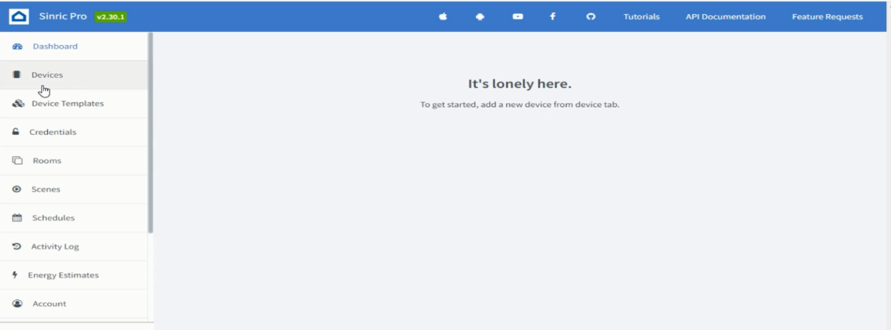
Login into your Sinric Pro account and click on the devices. If you want to learn how to register a free account then you should read my getting started article on the Sinric Pro.
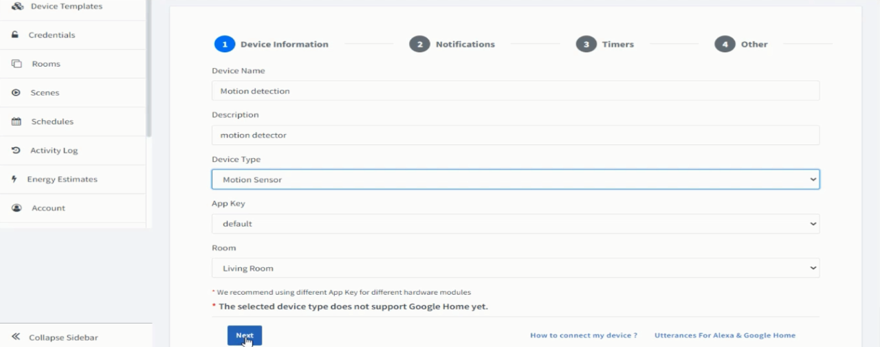
While the Devices is selected, click on the Add Device Button and Fill all the details.
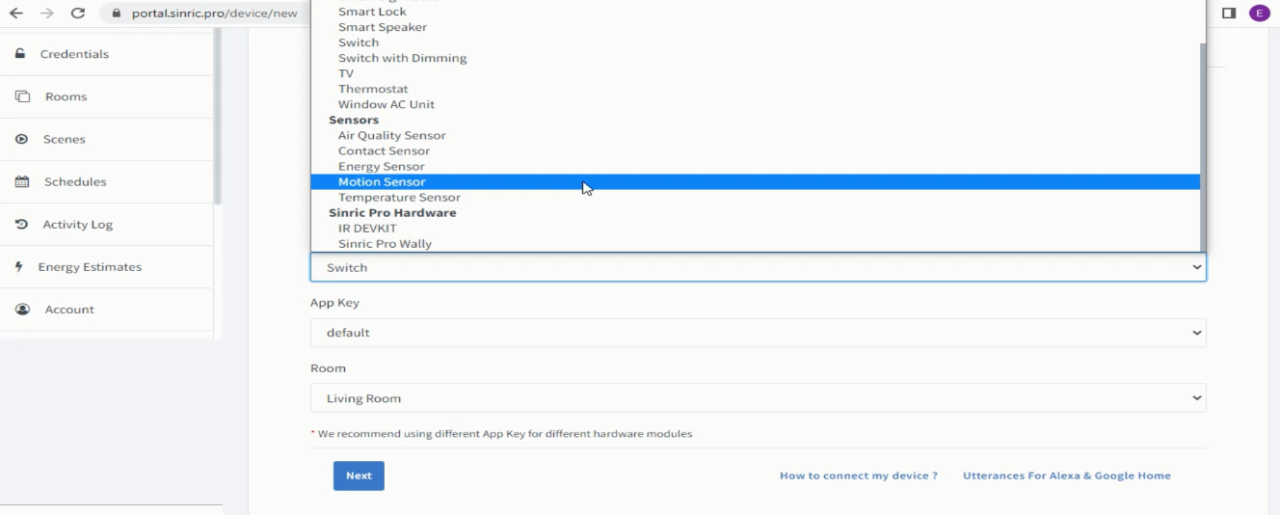
Then click on the device type and select the motion sensor
Then click on the next button
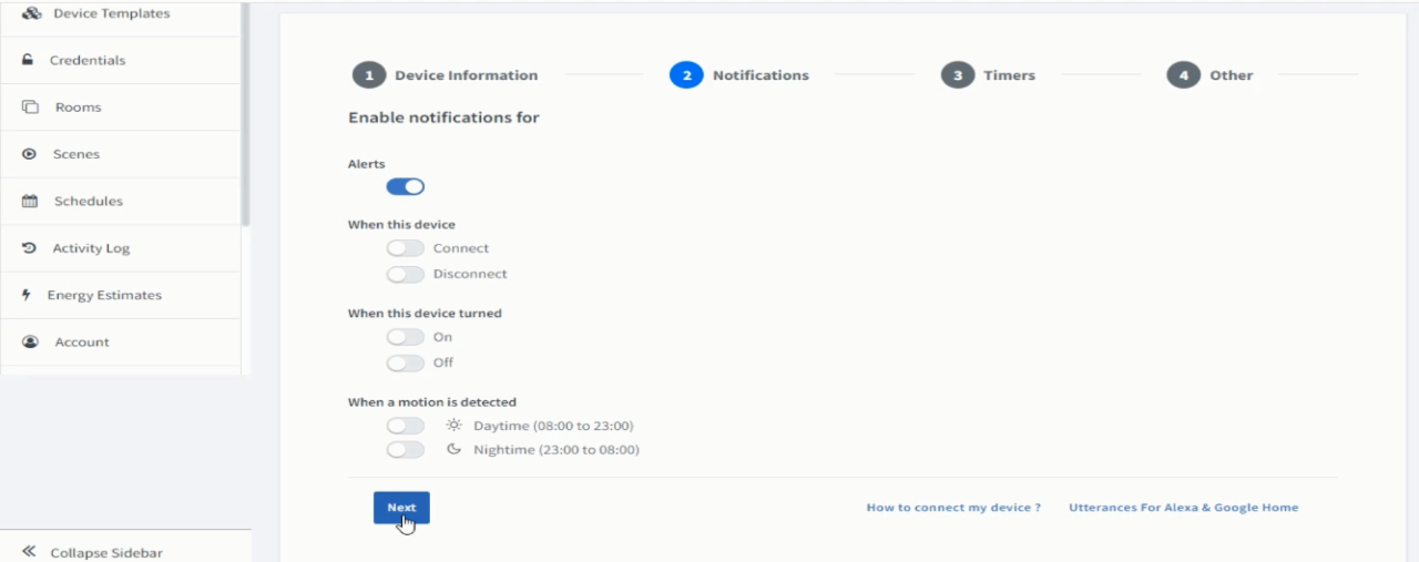
On the Notifications Tab, you can enable notifications for Alerts and when the device is connected or disconnected and when the device is turned ON or turned OFF. For now, I am going to continue with only the Alerts being enabled, so I am going to click on the Next button.
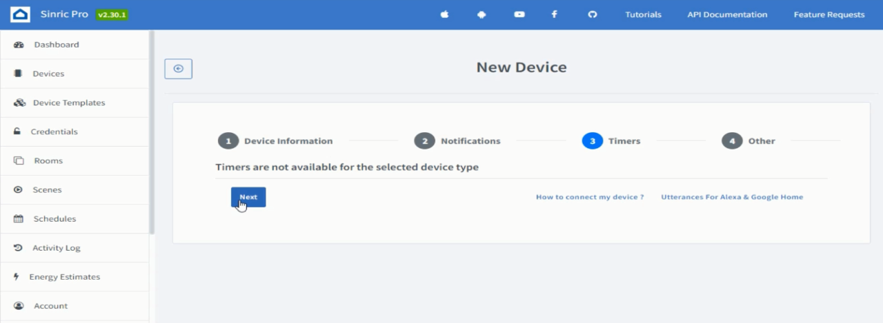
Then in the timers click on the next
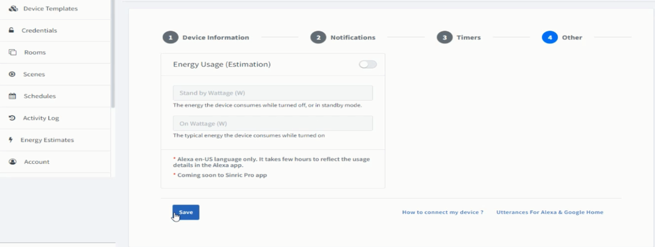
Finally, click on the Save button.
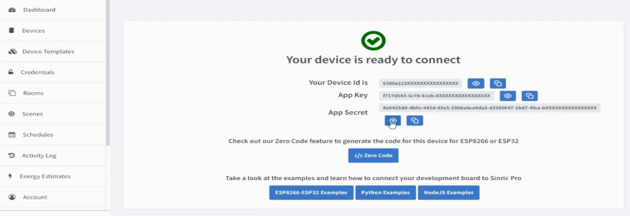
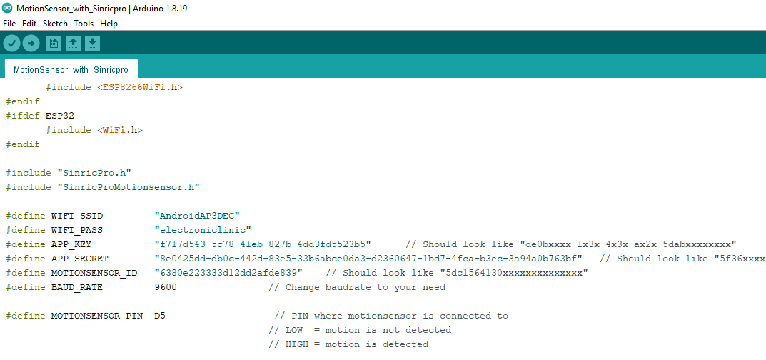
Our device is ready and now we will connect it to Nodemcu ESP8266 WiFi module. For this we will use the Device ID, App Key, and App Secret in the programming. For this, start by copying the Device Id, open the programming and past it next to the MOTIONSENSOR_ID. And follow the same exact steps for the App Key and App Secret.
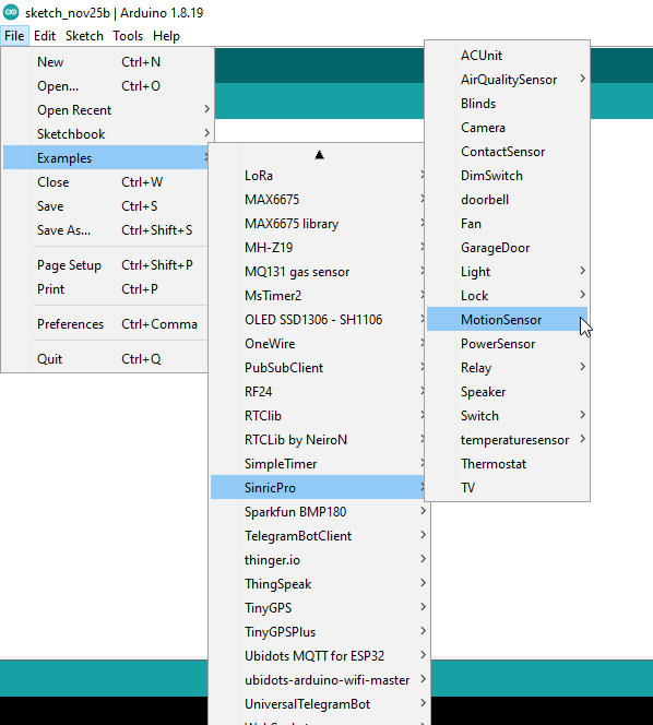
Now open the motion sensor example in the Arduino ide.
If you don’t see SinricPro in Examples, it means you have not installed the Sinric Pro library. To install the Sinric Pro Library read my previous article on the Sinric Pro. Once, you have installed the Sinric Pro library then you will be able to find the SinricPro. So Go ahead and open the MotionSensor example and paste the Credentials.
Invisible Security system Project Code:
/
|
1 2 3 4 5 6 7 8 9 10 11 12 13 14 15 16 17 18 19 20 21 22 23 24 25 26 27 28 29 30 31 32 33 34 35 36 37 38 39 40 41 42 43 44 45 46 47 48 49 50 51 52 53 54 55 56 57 58 59 60 61 62 63 64 65 66 67 68 69 70 71 72 73 74 75 76 77 78 79 80 81 82 83 84 85 86 87 88 89 90 91 92 93 94 95 96 97 98 99 100 101 102 103 104 105 106 107 108 109 110 111 112 113 114 115 116 117 118 119 120 121 122 123 124 125 126 127 128 129 130 131 132 133 134 |
/* * Example for SinricPro Motionsensor device: * - Setup motionsensor device * - Support onPowerState to turn on / turn off motion sensor * - Checks a motion sensor connected to MOTIONSENSOR_PIN and send event if state changed * * If you encounter any issues: * - check the readme.md at https://github.com/sinricpro/esp8266-esp32-sdk/blob/master/README.md * - ensure all dependent libraries are installed * - see https://github.com/sinricpro/esp8266-esp32-sdk/blob/master/README.md#arduinoide * - see https://github.com/sinricpro/esp8266-esp32-sdk/blob/master/README.md#dependencies * - open serial monitor and check whats happening * - check full user documentation at https://sinricpro.github.io/esp8266-esp32-sdk * - visit https://github.com/sinricpro/esp8266-esp32-sdk/issues and check for existing issues or open a new one */ // Uncomment the following line to enable serial debug output //#define ENABLE_DEBUG #ifdef ENABLE_DEBUG #define DEBUG_ESP_PORT Serial #define NODEBUG_WEBSOCKETS #define NDEBUG #endif #include <Arduino.h> #ifdef ESP8266 #include <ESP8266WiFi.h> #endif #ifdef ESP32 #include <WiFi.h> #endif #include "SinricPro.h" #include "SinricProMotionsensor.h" #define WIFI_SSID "AndroidAP3DEC" #define WIFI_PASS "electroniclinic" #define APP_KEY "f717d543-5c78-41eb-827b-4dd3fd5523b5" // Should look like "de0bxxxx-1x3x-4x3x-ax2x-5dabxxxxxxxx" #define APP_SECRET "8e0425dd-db0c-442d-83e5-33b6abce0da3-d2360647-1bd7-4fca-b3ec-3a94a0b763bf" // Should look like "5f36xxxx-x3x7-4x3x-xexe-e86724a9xxxx-4c4axxxx-3x3x-x5xe-x9x3-333d65xxxxxx" #define MOTIONSENSOR_ID "6380e223333d12dd2afde839" // Should look like "5dc1564130xxxxxxxxxxxxxx" #define BAUD_RATE 9600 // Change baudrate to your need #define MOTIONSENSOR_PIN D5 // PIN where motionsensor is connected to // LOW = motion is not detected // HIGH = motion is detected bool myPowerState = true; // assume device is turned on bool lastMotionState = false; unsigned long lastChange = 0; /** * @brief Checks motionsensor connected to MOTIONSENSOR_PIN * * If motion sensor state has changed, send event to SinricPro Server * state from digitalRead(): * HIGH = motion detected * LOW = motion not detected */ void handleMotionsensor() { if (!myPowerState) return; // if device switched off...do nothing unsigned long actualMillis = millis(); if (actualMillis - lastChange < 8000) return; // debounce motionsensor state transitions (same as debouncing a pushbutton) bool actualMotionState = digitalRead(MOTIONSENSOR_PIN); // read actual state of motion sensor if (actualMotionState != lastMotionState) { // if state has changed Serial.printf("Motion %s\r\n", actualMotionState?"detected":"not detected"); lastMotionState = actualMotionState; // update last known state lastChange = actualMillis; // update debounce time SinricProMotionsensor &myMotionsensor = SinricPro[MOTIONSENSOR_ID]; // get motion sensor device myMotionsensor.sendMotionEvent(actualMotionState); } } /** * @brief Callback for setPowerState request * * @param deviceId String containing deviceId (useful if this callback used by multiple devices) * @param[in] state bool true=turn on device / false=turn off device * @param[out] state bool true=device turned on / false=device turned off * @return true request handled properly * @return false request can't be handled because some kind of error happened */ bool onPowerState(const String &deviceId, bool &state) { Serial.printf("Device %s turned %s (via SinricPro) \r\n", deviceId.c_str(), state?"on":"off"); myPowerState = state; return true; // request handled properly } // setup function for WiFi connection void setupWiFi() { Serial.printf("\r\n[Wifi]: Connecting"); WiFi.begin(WIFI_SSID, WIFI_PASS); while (WiFi.status() != WL_CONNECTED) { Serial.printf("."); delay(250); } IPAddress localIP = WiFi.localIP(); Serial.printf("connected!\r\n[WiFi]: IP-Address is %d.%d.%d.%d\r\n", localIP[0], localIP[1], localIP[2], localIP[3]); } // setup function for SinricPro void setupSinricPro() { // add device to SinricPro SinricProMotionsensor& myMotionsensor = SinricPro[MOTIONSENSOR_ID]; // set callback function to device myMotionsensor.onPowerState(onPowerState); // setup SinricPro SinricPro.onConnected([](){ Serial.printf("Connected to SinricPro\r\n"); }); SinricPro.onDisconnected([](){ Serial.printf("Disconnected from SinricPro\r\n"); }); SinricPro.begin(APP_KEY, APP_SECRET); } // main setup function void setup() { Serial.begin(BAUD_RATE); Serial.printf("\r\n\r\n"); pinMode(MOTIONSENSOR_PIN, INPUT); setupWiFi(); setupSinricPro(); } void loop() { handleMotionsensor(); SinricPro.handle(); } |
Now, after you have setup everything correctly. Finally, you can upload the program. Make sure you have installed the Nodemcu ESP8266 Board; if not, then ready my article on how to get started with Nodemcu ESP8266. In this article, I have explained how to install the Nodemcu ESP8266 board manager URL link.
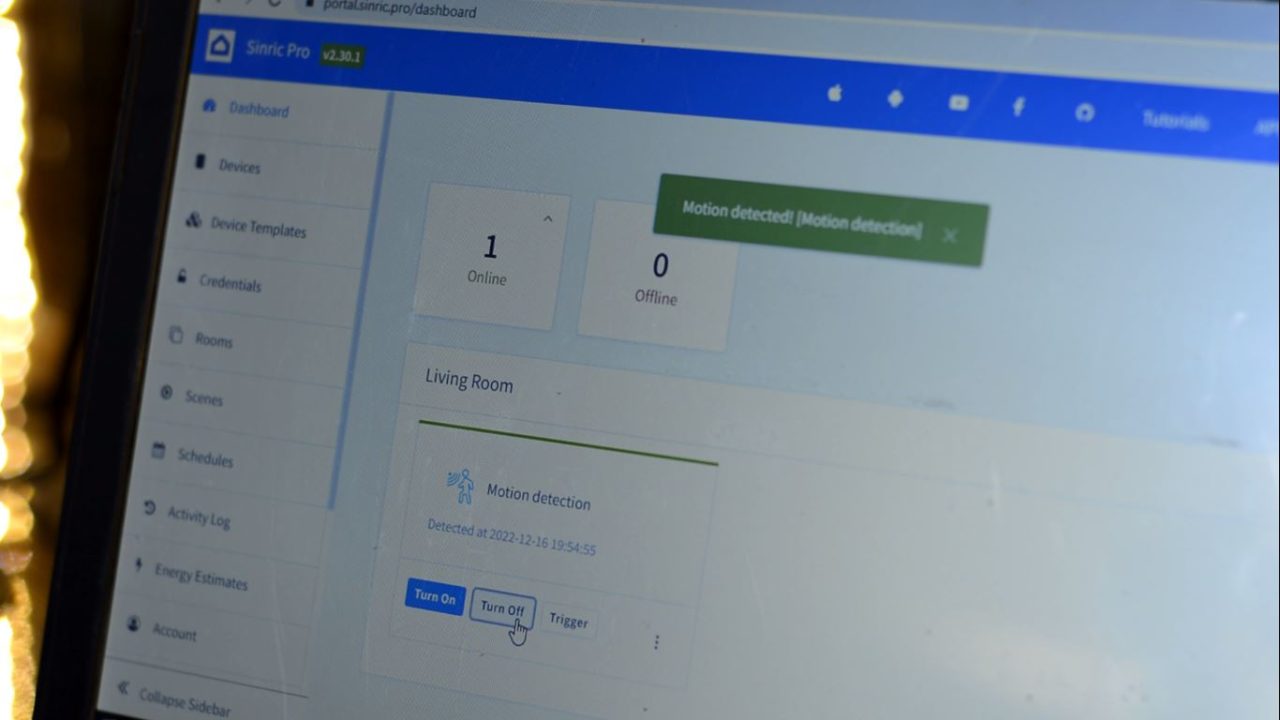
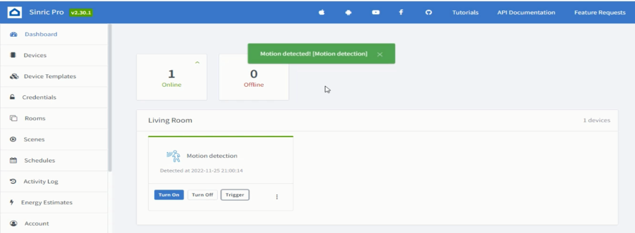
Anyway, after you have successfully upload the program. Make sure your WiFi is ON and your Nodemcu ESP8266 is connected to it. Go back to Sinric Pro. You can see 1 device is online and now if I move my hand it will detect my movement and here it is, it just detected me.
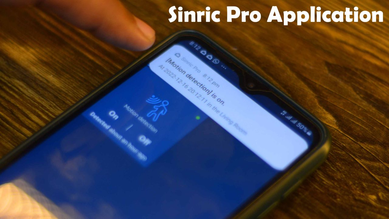
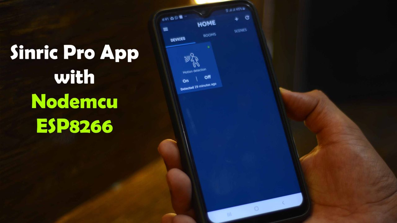
Download and install the Sinric Pro cell phone application and login with your registered email id and that’s it. You will get a readymade APP, you don’t have to do any settings. If you want to make any changes you can go back to your Sinric Pro Dashboard. Any changes you will make in the dashboard will automatically reflect on the Sinric Pro Mobile Application.
Now, I can monitor my workshop from any part of the world. So, if in case I receive any notifications, I can call my brother to go and check if there is someone. So, that’s all for now.
For Practical Demonstration watch video tutorial.
Watch Video Tutorial:
