Sinric Pro ESP32 for Home Automation and Sensor Monitoring
Last Updated on September 21, 2024 by Engr. Shahzada Fahad
Table of Contents
Sinric Pro ESP32:
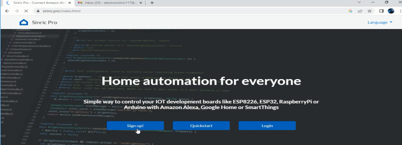
Sinric Pro ESP32 for Home Automation and Sensor Monitoring-If you are a Home Automation Lover and you have been trying different IoT platforms for controlling your home appliances and for monitoring different types of sensors then you need to read this article from start to the very end. Because in this project, the IoT platform that I am going to use is specifically designed for Home Automation.
I am sure only a few of you guys might know about the Sinric Pro which is also an IoT platform and can be used with IoT development boards like ESP8266, ESP32, Raspberry Pi, Arduino, Amazon Alexa, Google Home or SmartThings.
By the way, you can also use Blynk 2.0, Arduino IoT Cloud, Ubidots, ThingSpeak, Firebase, Adafruit Io, InfluxDB, Thinger.io, and so on, there is a long list of IoT platforms. And I have already used all these platforms; you can check my category onIOT projects.
Anyway, all these platforms which I just mentioned are not specifically designed for Home Automation and I am not saying these are bad for Home Automation, but the Sinric Pro gives you that Elite class feeling. You can get it connected to Google Home or SmartThings and Amazon Alexa and start controlling all your Home appliances using voice commands and of course you can also monitor different types of sensors.
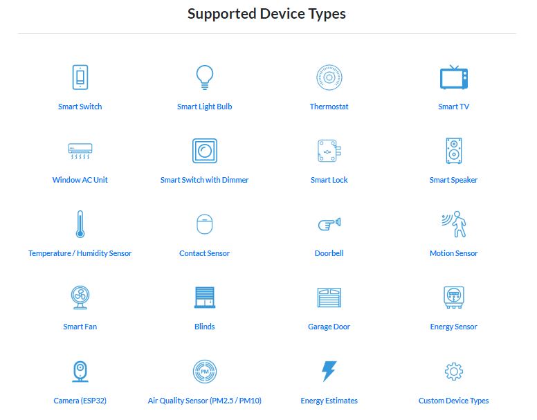
Here is a list of all the supported devices, just click on any device and follow the instructions to set up your device. Besides this, you can also Make Your Own Device Type. I will practically explain this in a few seconds.
Sinric Pro is available on App Store and also on Google Play. So you can use Sinric Pro on iPhones, IPads, and android cell phones.
As I said earlier, you can make your own device type, and here it is.
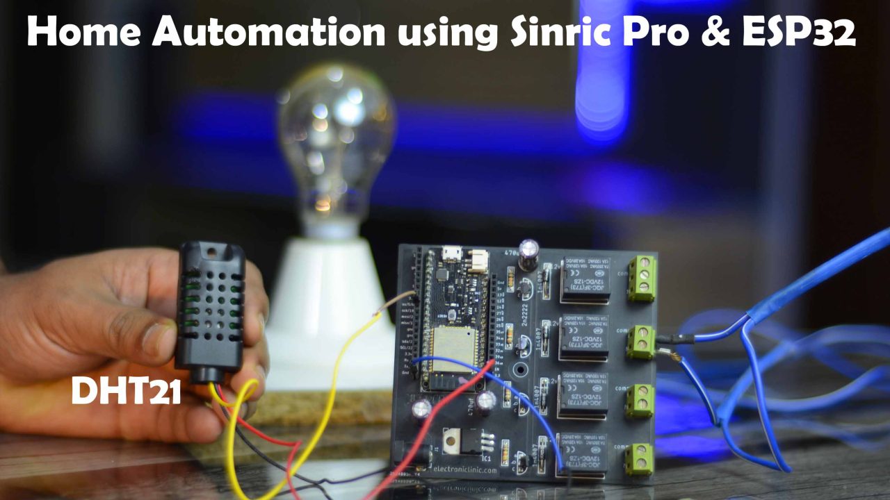
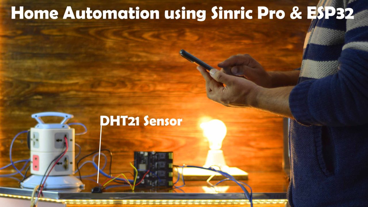
I am using my ESP32 Development board. Right now, out of these 4 relays, I am using only one relay that I am using to control a 220Vac Bulb and I have also connected the DHT21 Temperature and Humidity sensor.
As usual, before, I am going to explain the circuit diagram, Sinric Pro setup, and ESP32 programming, first I am going to share with you the final test results and afterwards I will explain everything else.
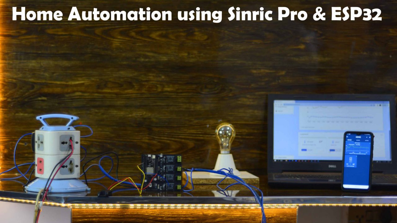
I have powered up the ESP32 development board and I have also connected the Bulb to 220Vac supply. Make sure you wear protective gloves while dealing with the 220Vac supply and when the AC supply is ON never touch the Relay module contacts. Anyway, right now my ESP32 development board, my Laptop, and my cell phone all are connected to the WiFi. You can use the same WiFi network or different WiFi networks it’s totally upto you. Unlike the Blynk 2.0 and Arduino IoT Cloud, you can use the Sinric Prodashboard on the Laptop or you can use the Sinric Pro cell phone application. First, I am going to start with the Sinric Pro Dashboard.
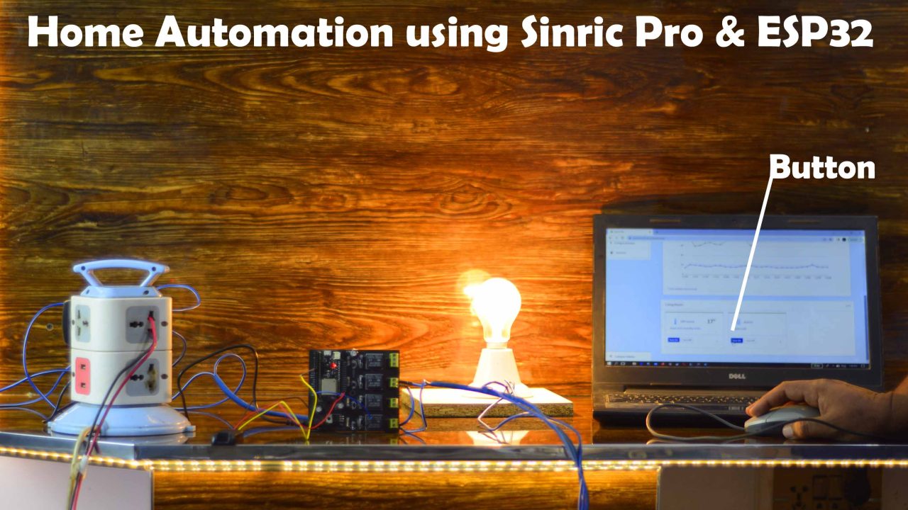
I was able to control this Bulb using a button. For the practical demonstration watch video tutorial available on my YouTube channel Electronic Clinic.
I was also able to control the same light using my Sinric Pro Mobile application.
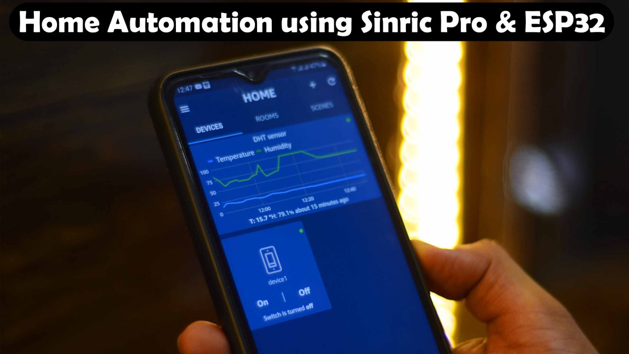
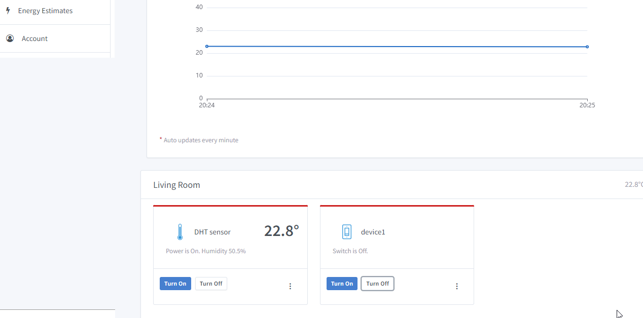
Using the Sinric Pro Mobile Application I was able to control the 110/220Vac light Bulb and I was also able to monitor the Temperature and Humidity values. Its totally up to you; if you want to use Sinric Pro computer dashboard or the Sinric Pro Mobile Application or you want to use both at the same time.
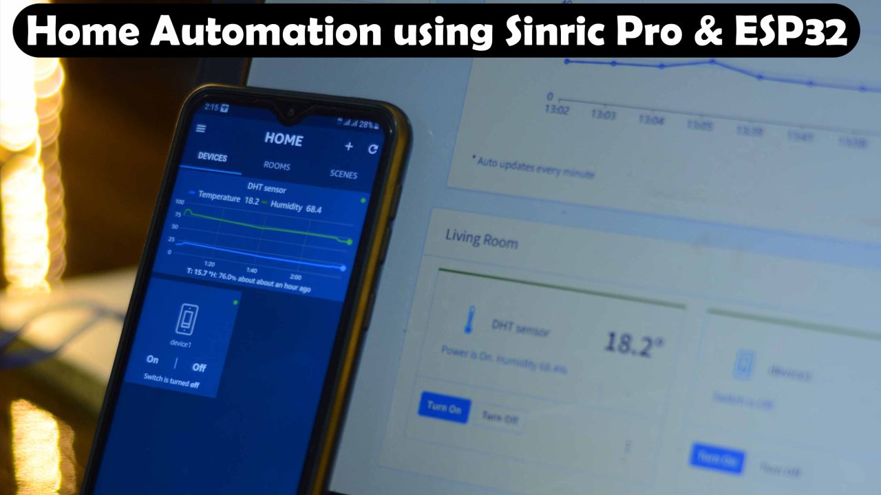
The Sinric Pro Mobile Application and the Sinric Pro Web dashboard both are updated at the same time. You can see the same temperature value 18.2Co . Personally, I really like Sinric Pro for Home automation and in my upcoming tutorial, I will use this in an advanced-level security system. Anyway, I am sure by now, you might have got an idea of how does this system work. So, without any further delay let’s get started!!!
Amazon Links:
- ESP32 WiFi + Bluetooth Module(Recommended)
- DHT21 Temperature and Humidity Sensor
- 5v one channel relay module
*Disclosure: These are affiliate links. As an Amazon Associate I earn from qualifying purchases.
DHT21or AM2301:
AM2301 is a digital temperature and humidity sensor module made using a capacitive humidity sensor, a high precision temperature sensor and an 8 bit microcontroller. Former name of this sensor was DHT21. This module provides extremely accurate outputs as it is digitally calibrated using the coefficients stored in the microcontroller. It has a wide operating voltage range, 3.3V ~ 5.2V makes its interface easy with a wide variety of devices. AM2301 sensor module can be easily interfaced with Arduino Boards, Raspberry Pi and other microcontroller units with its single bus interface.

Features:
- Ultra low power
- Fast response
- Relative humidity and temperature measurement
- Full range temperature compensation
- Excellent long term stability
- Long transmission distance
- High accuracy
- No need of extra components
- Excellent long term stability
- Calibrated digital output
Pin Out
- Red VDD Power (3.3V ~ 5.2V)
- Yellow SDA Serial Data, Dual Port
- Black GND Ground
Applications:
- HVAC (Heating, Ventilating and Air Conditioning)
- Dehumidifier
- Testing and inspection equipment
- Home appliances
- Data loggers
- Humidity regulator
- Weather stations
DHT21 & Relay interfacing with ESP32:
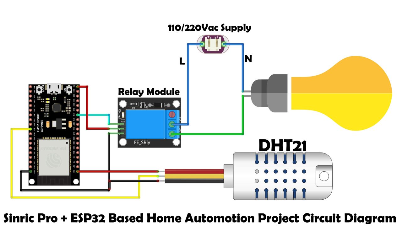
I am using digital pin 12 on the ESP32 to control the relay module that I am using to turn ON/OFF the Bulb. The Neutral wire is directly connected with the Bulb while the live wire from the 110/220Vac supply is connected with the common contact of the relay module and the Normally Open contact of the relay module is connected with the Bulb. Now, by turning ON and turning OFF this relay I can turn ON and turn OFF the bulb.
The VCC and ground pins of the DHT21 Temperature and Humidity sensor are connected with the 3.3V and GND pins while the Data pin of the DHT21 sensor is connected with the digital pin 5 of the ESP32 WiFi + Bluetooth module.
These are the minimal connections you will need to start with. You can clearly see, in the circuit diagram there is no 5V regulated power supply. So, you will have to use your laptop to power up the ESP32 module.
Or you can use my ESP32 development board which has this 5V regulated power supply. So the main advantage of this board is, you won’t need a laptop to power up the ESP32 board. You can use a 12V adaptor, battery, or a solar panel. So, if you want to make the same ESP32 development board for testing all your ESP32 based projects then you can download the PCB Gerber files from the article available on www.electroniclinic.com I will provide a link in the description.
Anyway, I connected the 220Vac Bulb and the DHT21 Temperature and humidity sensor as per the circuit diagram and now let’s start with the Sinric Pro setup.
Sinric Pro Setup:
Open the Sinric Pro website and click on the Sign Up! Button to register a free account.
With free account you are only allowed to use 3 devices for free with no limitations. And if you need more devices then it’s just 3 dollars per device for a year, this is pretty cool and quite affordable. You don’t have to pay for the resources you are not using.
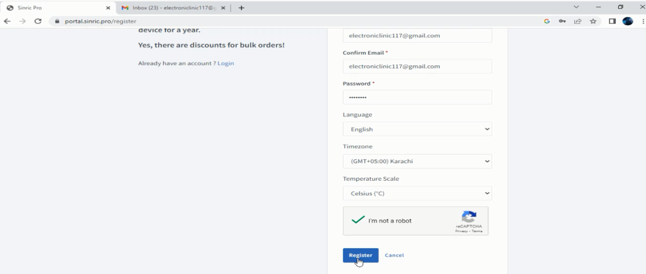
Anyway after filling the form click on the Register button. You will get a confirmation email, so open your email and click on the confirm button.
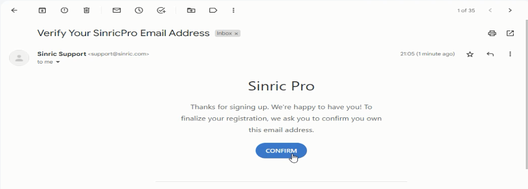
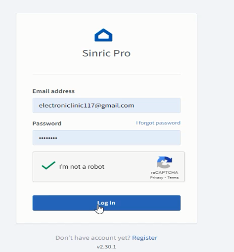
After clicking the CONFIRM button, simply enter your registered email id and password.
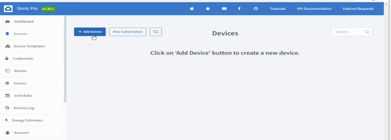
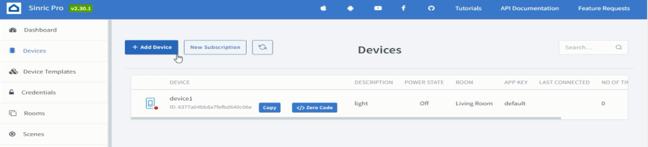
While the Devices is selected, click on the Add Device Button.
Fill all the details.
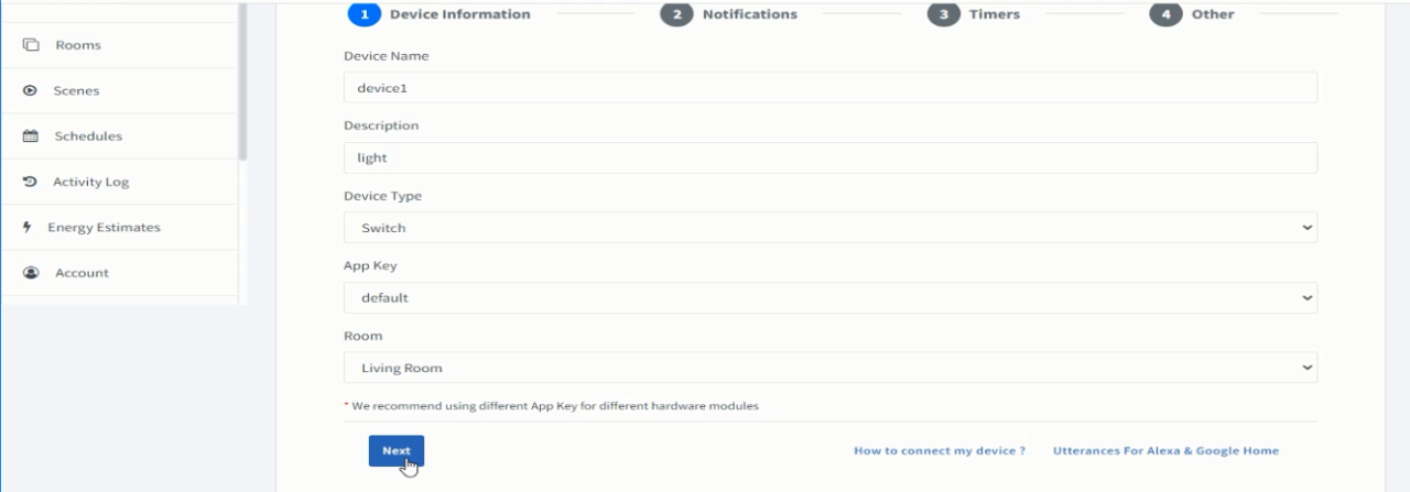
Write the Device name, Description, select the Device Type, App Key, and Room. As I am doing it for the switch so I am going to leave the device type as it is. And I am also going to continue with the default App Key and the Living room is just fine for this example, but if you want you can select a different room. Anyway, when you are done with filling the Device Information, click on the Next button.
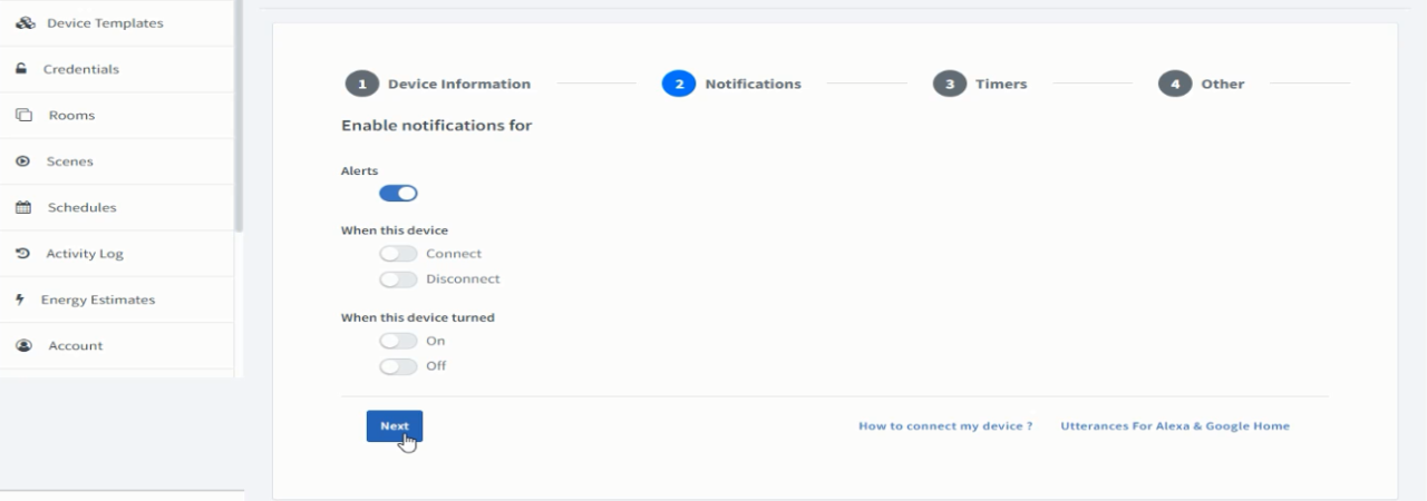
On the Notifications Tab, you can enable notifications for Alerts and when the device is connected or disconnected and when the device is turned ON or turned OFF. For now, I am going to continue with only the Alerts being enabled, so I am going to click on the Next button.
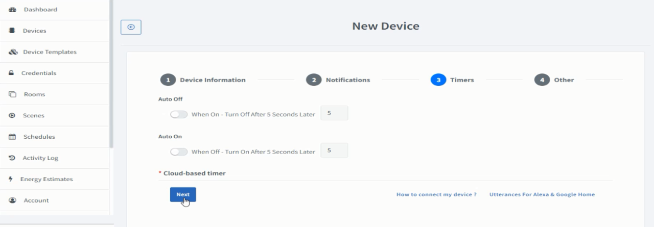
You can use the Cloud-based timer to automatically turn OFF or Turn on the device. Since I want to do it manually so I am not going to use the Cloud-based timer. But I can tell you where to use it. Let’s say you have installed a PIR sensor and when the PIR Sensor detects any movement, you want the Bulb or Alarm to turn ON for a specific period of time then you can use this. Anyway for now, I am going to click on the Next button.
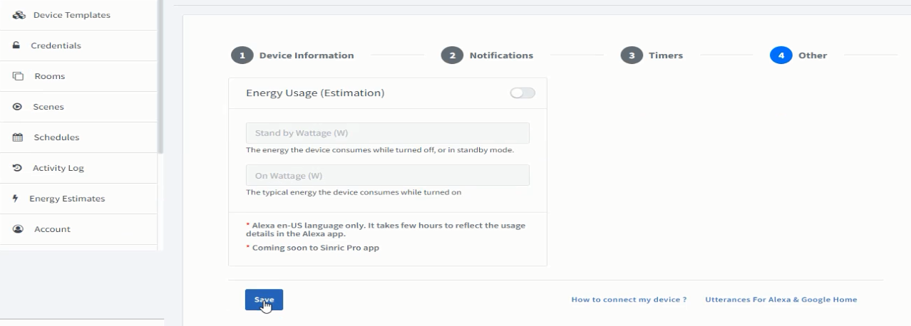
Finally, you can click on the Save button.
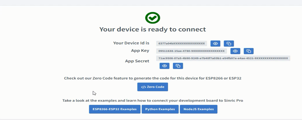
Later we will need the Device ID, App Key, and App Secret to connect the device that we just created with the ESP32 module. Anyway, let’s add another device but this time it’s a sensor not a switch.
Click on the Add Device, write the device name and some description. Now, click on the Device type.
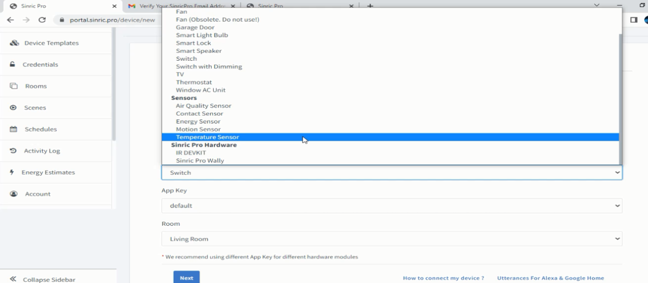
You can see this long list of the devices, select the one as per your needs, in my case I am going to select Temperature Sensor.
On the Notifications tab, you can also turn ON alert for when the temperatures rises above certain value or falls below a certain value. This is pretty cool, on the ESP32 side, you don’t need to write conditions. Anyway, for now, I don’t need this, so I will keep it as it is, I can always come back and change this so I am going to click on the Next button.
No Cloud-based timers are available so click on the Next button.
Finally, click on the save button. Our two devices are ready and now we will connect these devices with the ESP32 WiFi + Bluetooth module.
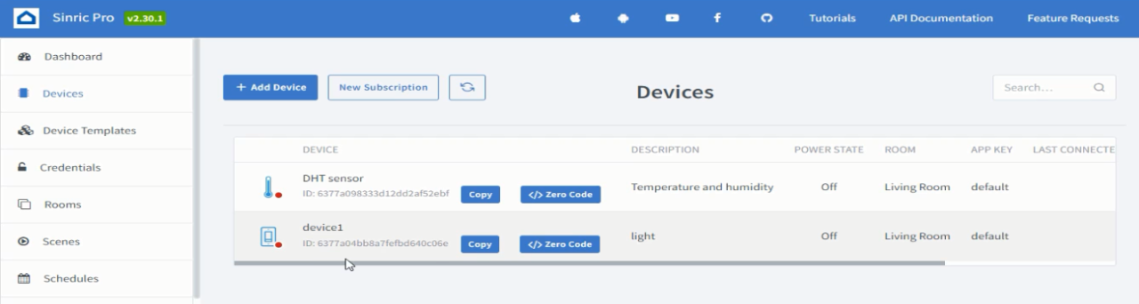
For this click on the devices, you can see the two devices DHT11 Temperature and Humidity sensor and Device1 that’s a light switch.
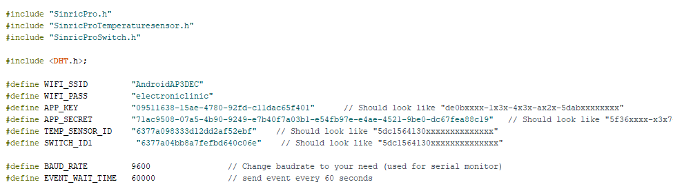
First let’s connect these devices, for this click on the copy button next to the device1, Open the programming, and paste this next to the SWITCH_ID1, and exactly the same way do it for the DHT Sensor as you can see in the image given below. If you don’t get it, you can watch the video tutorial available on my YouTube channel Electronic Clinic.
Now, click on the Credentials.
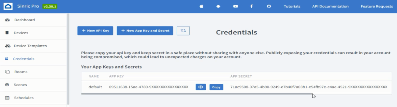
Copy the App key and paste it next to the APP_KEY in the programming. Do the same exact thing for the APP SECRET.
Now, we will install the SinricPro.h library, for this go to the Sketch Menu, then to Include Library, and click on the Manage Libraries. Search for the Sinric Pro.
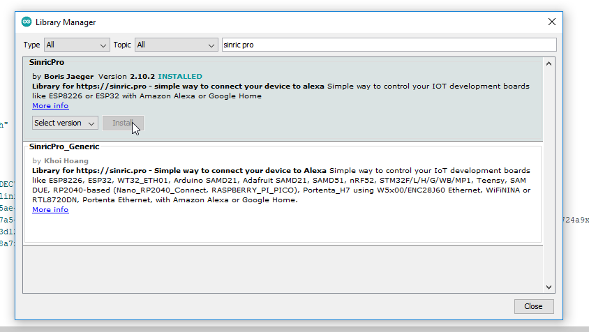
As you can see I have already installed the SinricPro library.
If you are using the ESP32 or Nodemcu ESP8266 for the first time, then you will also need to install the ESP32 or ESP8266 board in the Arduino IDE, for this you can read my getting started articles on the ESP32 and Nodemcu ESP8266 WiFi modules
Sinric Pro ESP32 Programming:
|
1 2 3 4 5 6 7 8 9 10 11 12 13 14 15 16 17 18 19 20 21 22 23 24 25 26 27 28 29 30 31 32 33 34 35 36 37 38 39 40 41 42 43 44 45 46 47 48 49 50 51 52 53 54 55 56 57 58 59 60 61 62 63 64 65 66 67 68 69 70 71 72 73 74 75 76 77 78 79 80 81 82 83 84 85 86 87 88 89 90 91 92 93 94 95 96 97 98 99 100 101 102 103 104 105 106 107 108 109 110 111 112 113 114 115 116 117 118 119 120 121 122 123 124 125 126 127 128 129 130 131 132 133 134 135 136 137 138 139 140 141 142 143 144 145 146 147 148 149 150 151 152 153 154 |
// Uncomment the following line to enable serial debug output //#define ENABLE_DEBUG #ifdef ENABLE_DEBUG #define DEBUG_ESP_PORT Serial #define NODEBUG_WEBSOCKETS #define NDEBUG #endif #include <Arduino.h> #ifdef ESP8266 #include <ESP8266WiFi.h> #endif #ifdef ESP32 #include <WiFi.h> #endif #include "SinricPro.h" #include "SinricProTemperaturesensor.h" #include "SinricProSwitch.h" #include <DHT.h>; #define WIFI_SSID "AndroidAP3DEC" #define WIFI_PASS "electroniclinic" #define APP_KEY "09511638-15ae-4780-92fd-c11dac65f401" // Should look like "de0bxxxx-1x3x-4x3x-ax2x-5dabxxxxxxxx" #define APP_SECRET "71ac9508-07a5-4b90-9249-e7b40f7a03b1-e54fb97e-e4ae-4521-9be0-dc67fea88c19" // Should look like "5f36xxxx-x3x7-4x3x-xexe-e86724a9xxxx-4c4axxxx-3x3x-x5xe-x9x3-333d65xxxxxx" #define TEMP_SENSOR_ID "6377a098333d12dd2af52ebf" // Should look like "5dc1564130xxxxxxxxxxxxxx" #define SWITCH_ID1 "6377a04bb8a7fefbd640c06e" // Should look like "5dc1564130xxxxxxxxxxxxxx" #define BAUD_RATE 9600 // Change baudrate to your need (used for serial monitor) #define EVENT_WAIT_TIME 60000 // send event every 60 seconds #ifdef ESP8266 #define DHT_PIN D5 #endif #ifdef ESP32 #define DHT_PIN 5 #define RELAY_PIN 12 #endif #define DHTTYPE DHT21 //DHT 21 (AM2301) DHT dht(DHT_PIN, DHTTYPE); //Initialize DHT sensor for normal 16mhz Arduino bool deviceIsOn; // Temeprature sensor on/off state float temperature; // actual temperature float humidity; // actual humidity float lastTemperature; // last known temperature (for compare) float lastHumidity; // last known humidity (for compare) unsigned long lastEvent = (-EVENT_WAIT_TIME); // last time event has been sent /* bool onPowerState(String deviceId, bool &state) * * Callback for setPowerState request * parameters * String deviceId (r) * contains deviceId (useful if this callback used by multiple devices) * bool &state (r/w) * contains the requested state (true:on / false:off) * must return the new state * * return * true if request should be marked as handled correctly / false if not */ bool onPowerState(const String &deviceId, bool &state) { Serial.printf("Temperaturesensor turned %s (via SinricPro) \r\n", state?"on":"off"); deviceIsOn = state; // turn on / off temperature sensor digitalWrite(RELAY_PIN, state); return true; // request handled properly } /* handleTemperatatureSensor() * - Checks if Temperaturesensor is turned on * - Checks if time since last event > EVENT_WAIT_TIME to prevent sending too much events * - Get actual temperature and humidity and check if these values are valid * - Compares actual temperature and humidity to last known temperature and humidity * - Send event to SinricPro Server if temperature or humidity changed */ void handleTemperaturesensor() { if (deviceIsOn == false) return; // device is off...do nothing unsigned long actualMillis = millis(); if (actualMillis - lastEvent < EVENT_WAIT_TIME) return; //only check every EVENT_WAIT_TIME milliseconds temperature = dht.readTemperature(); // get actual temperature in °C // temperature = dht.getTemperature() * 1.8f + 32; // get actual temperature in °F humidity = dht.readHumidity(); // get actual humidity if (isnan(temperature) || isnan(humidity)) { // reading failed... Serial.printf("DHT reading failed!\r\n"); // print error message return; // try again next time } if (temperature == lastTemperature || humidity == lastHumidity) return; // if no values changed do nothing... SinricProTemperaturesensor &mySensor = SinricPro[TEMP_SENSOR_ID]; // get temperaturesensor device bool success = mySensor.sendTemperatureEvent(temperature, humidity); // send event if (success) { // if event was sent successfuly, print temperature and humidity to serial Serial.printf("Temperature: %2.1f Celsius\tHumidity: %2.1f%%\r\n", temperature, humidity); } else { // if sending event failed, print error message Serial.printf("Something went wrong...could not send Event to server!\r\n"); } lastTemperature = temperature; // save actual temperature for next compare lastHumidity = humidity; // save actual humidity for next compare lastEvent = actualMillis; // save actual time for next compare } // setup function for WiFi connection void setupWiFi() { Serial.printf("\r\n[Wifi]: Connecting"); WiFi.begin(WIFI_SSID, WIFI_PASS); while (WiFi.status() != WL_CONNECTED) { Serial.printf("."); delay(250); } IPAddress localIP = WiFi.localIP(); Serial.printf("connected!\r\n[WiFi]: IP-Address is %d.%d.%d.%d\r\n", localIP[0], localIP[1], localIP[2], localIP[3]); } // setup function for SinricPro void setupSinricPro() { // add device to SinricPro SinricProTemperaturesensor &mySensor = SinricPro[TEMP_SENSOR_ID]; SinricProSwitch& mySwitch = SinricPro[SWITCH_ID1]; mySensor.onPowerState(onPowerState); mySwitch.onPowerState(onPowerState); // setup SinricPro SinricPro.onConnected([](){ Serial.printf("Connected to SinricPro\r\n"); }); SinricPro.onDisconnected([](){ Serial.printf("Disconnected from SinricPro\r\n"); }); //SinricPro.restoreDeviceStates(true); // Uncomment to restore the last known state from the server. SinricPro.begin(APP_KEY, APP_SECRET); } // main setup function void setup() { Serial.begin(BAUD_RATE); Serial.printf("\r\n\r\n"); pinMode(RELAY_PIN, OUTPUT); SinricProSwitch& mySwitch = SinricPro[SWITCH_ID1]; mySwitch.onPowerState(onPowerState); dht.begin(); setupWiFi(); setupSinricPro(); } void loop() { SinricPro.handle(); handleTemperaturesensor(); } |
Finally, before clicking on the upload button, first, make sure you have selected the correct ESP32 board and the correct communication port. After the program has been uploaded, go back to Sinric Pro and you should be able to see the two devices online.
You can turn ON and turn OFF the devices using the Sinric Pro on your Laptop, you can see the temperature and humidity values and you can also do it using your cell phone.
Sinric Pro ESP32 Mobile Setup:
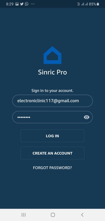
Go to Play Store and search for the Sinric Pro and install it. As you can see I have already installed the Sinric Pro mobile App.

Open the Sinric Pro Home automation App. Enter your registered email id and password.
And here we go, the two devices are automatically added.

We don’t need to do any settings. For the practical demonstration watch video tutorial.
Watch Video Tutorial:

Discover more from Electronic Clinic
Subscribe to get the latest posts sent to your email.


Nice Project. Appreciate you providing so many details.
I think it would also make sense to use ESP32 Module with an adapter board alone instead of a full dev kit in some of the projects.
This will help engineers understand how ESP32 will be used in real products.
There is another issue in using the Dev kit as a whole although I understand this is just a demonstration project.
We see many designs where developers put the USB to UART (with auto reset and boot) on their custom hardware so that with the same interface they will be able to reprogram the board as well in the production & field easily.
But, this is not recommended because this poses a risk.
Someone can hack your hardware to do something else with their own firmware, or break it easy to make you look bad in front of the customer, all these things happen in real life.
So, you should not have an easy way exposed, to reflash your MCU.
What you should do is, have a 6-pin connector(RX, TX, 3.3V, GND, EN, IO0) on the board and buy a programmer board to do the programming in the production. For the field to have a secured OTA or secured physical interface.
I have already designed new boards, very soon I will start a new series on products designing.