Thinger.IO and ESP8266 based Home Automation Project
Last Updated on September 21, 2024 by Engr. Shahzada Fahad
Table of Contents
Thinger.io and ESP8266:
Thinger.IO and ESP8266 based Home Automation Project-Most of you guys might don’t know about Thinger.IO which is basically an IoT Cloud Platform. Unlike other IoT platforms including Arduino IoT Cloud, Blynk, Thingspeak, Adafruit IO, Google spreadsheet, Firebase, Cayenne, Ubidots, etc. The Thinger.io IoT Cloud Platform can also be used for monitoring different types of sensors and for controlling different types of electrical devices. Since this is my first project on the Thinger.io so I am going to start with a very simple project that is the Home automation project.
For this project you will need Nodemcu ESP8266 WiFi Module, You will also need a relay module, and 110/220Vac bulbs. As a beginner, it is good to start with some LEDs; because once you learn how to control LEDs then you can replace those LEDs with transistors, mosfets, and relays for controlling high ampere and high voltage electrical loads.

Anyway, this is the prototype model. I have connected everything as per the circuit diagram which I will explain in a minute.
For demonstration purposes, I am using 4 bulbs which are connected to 4 relays. Besides lights, you can use any other 110/220Vac loads or use any other DC type loads.
If you want to use 110/220Vac supply, you must not forget to use protective gloves, because 110/220Vac can prove fatal. So, as far as possible you must ensure the presence of a friend or any companion while carrying on work on such projects. When the AC supply is ON, do not touch the relay module.Let’s go ahead and start a practical demonstration so that you can see everything for yourself.
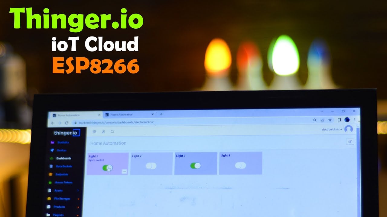
Right now the Nodemcu ESP8266 and Laptop both are connected with the WiFi. It doesn’t matter if you use the same or different WiFi networks. Now, I am going to open my Thinger.io Dashboard.

You can see I have added 4 buttons to control all the 4 lights. Since this is an IoT Platform so these four lights can be controlled from any part of the world provided if the internet connection is available. Anyway, you can see, right now all the 4 bulb are OFF. By turning ON and turn OFF any of these switches I can turn ON and turn OFF any bulb.

Right now, you can see I have turned ON Blub 1 and Bulb 3. I am sure by now, you might have got an idea of how does this system work. So, without any further delay let’s get started!!!
Amazon Links:
Disclosure: These are affiliate links. As an Amazon Associate I earn from qualifying purchases.
ESP8266 Home Automation Circuit:

4 relays are connected with the Nodemcu ESP8266 WiFi module digital pins D0, D1, D3, and D4. If you are using a 5V relay module then connect the VCC and GND pins of the relay module with the 5V and GND of the 5V power supply, and if you are using a 12V relay module then you will need to connect an external 12V DC power supply.
The Neutral wire from the 110/220Vac Supply is directly connected with all the 4 bulbs while the Phase wire is connected with the bulbs through relays. You can see the phase wire from the 110/220Vac supply is connected with the Common contact of all the relays while the Normally open contacts are connected with the Bulbs. Over here the relay is working just like an ordinary switch. So by turning ON and turn OFF the relay you can turn ON or turn OFF the bulb.
PCBs from JLCPCB:

These are the PCBs I received from JLCPCB. As you can see the Quality is really great. The black and blue color solder masks look amazing.

Anyway, this is how the PCB boards look after soldering. This is the Nodemcu ESP8266 development board and I am going to use this for testing all of my Nodemcu ESP8266 based iot projects. And this is the relay module. As I am using 12V SPDT type relays so using this DC Female Power Jack( “to which red and white wires are soldered”) I will use an external 12V power supply. Anyway, if you want to make the same ESP8266 development board and relay module then you can download the Gerber files.
Nodemcu ESP8266 Development board Gerber files
Now, let’s go ahead and start with the Thinger.io.
Thinger.io Dashboard Designing:
Go to the ThingerioIoT Cloud Platformand click on the sign up button.

Then enter the username, email, password, and other details and click on the sign up button

A verification email will be sent to your registered email account, next all you need is to simply login into your email account click on the verification link. Enter your login details and click on the login button.

Once your login into your thinger.io account, then click on the Devices.

Then click on the Create a device.

Then enter all the necessary information for the device.

Now, after filling all the device details, copy the Device id and open the programming which is given in the programming section below, and paste it next to the DEVICE_ID in the arduino_secrets.h.
Next, copy the Device Credentials and past it next to the DEVICE_CREDENTIAL in the programming.
The USERNAME in the arduino_secrets.h should be the same as your gmail id you used to register on the thinger.io cloud platform.

Finally, click on the Add Device. You will see 0 bytes transmitted and received as the device is offline because the program is not yet uploaded. So, let’s go back to the program and upload it to Nodemcu ESP8266.
Before, you upload the program, first you will need to install the ThingerESP8266 library. For this go to the Sketch menu, then to Include Library, and click on Manage Libraries. Search for the thinger.io. As you can see I have already installed the latest version of the thinger.io

If you are using the Nodemcu ESP8266 WiFi module for the first time then you will also need to install the Nodemcu ESP8266 board in the Arduino IDE, for this you can read my getting started article on the Nodemcu ESP8266.
After you have installed your Nodemcu ESP8266 Board and the required library. Next, copy the arduino_secrets.h and the main code given below. Make sure you keep the arduino_secrets.h in the same folder with arduino main code file .ino. If you don’t get it, watch the video tutorial on my YouTube channel Electronic Clinic.
Arduino_secrets.h:
|
1 2 3 4 5 6 |
#define USERNAME "electroniclinic" #define DEVICE_ID "nodemcu" #define DEVICE_CREDENTIAL "electronic" #define SSID "AndroidAP3DEC" #define SSID_PASSWORD "electroniclinic" |
Thinger.io ESP8266 Code:
|
1 2 3 4 5 6 7 8 9 10 11 12 13 14 15 16 17 18 19 20 21 22 23 24 25 26 27 28 29 30 31 32 33 34 35 36 37 38 39 40 |
#define THINGER_SERIAL_DEBUG #include <ThingerESP8266.h> #include "arduino_secrets.h" ThingerESP8266 thing(USERNAME, DEVICE_ID, DEVICE_CREDENTIAL); int light1=D0; int light2=D1; int light3=D3; int light4=D4; void setup() { // open serial for monitoring Serial.begin(115200); // set builtin led as output pinMode(light1, OUTPUT); pinMode(light2, OUTPUT); pinMode(light3, OUTPUT); pinMode(light4, OUTPUT); // add WiFi credentials thing.add_wifi(SSID, SSID_PASSWORD); // // digital pin control example (i.e. turning on/off a light, a relay, configuring a parameter, etc) thing["led"] << digitalPin(light1); thing["led1"] << digitalPin(light2); thing["led2"] << digitalPin(light3); thing["led3"] << digitalPin(light4); // more details at http://docs.thinger.io/arduino/ } void loop() { thing.handle(); } |
Make sure you modify the arduino_secrets.h header file as per your device settings. Anyway, after you are done with all the required things next you can upload the code. Make sure you have selected the right communication port and the right nodemcu board before you click on the Upload button.
After the program has been successfully uploaded, now go back to thinger.io. Wait for a while or click on the refresh button. Now, you can see the device is online as you can see in the image below.

Now we will create a dashboard for controlling all the 4 lights; for this click on the Dashboards and click on the Create a Dashboard.

Then enter the dashboard details and click on the Add Dashboard.

Then click on the edit and click on the Add widget.

Then fill the form for the widget setting and select the on/off state which will be used to control the light or led.

Then enter the target value by selecting the Device Resource.

After selecting Resource another box will open in which we will select the device.

Then select the resource which will be used to turn ON and OFF the light.

After that a button will be added to the dashboard.

In the similar way we will add all the other three buttons.

All the 4 switches have been added and now my Home Automation Dashboard is ready. Now, I can use these buttons to control my Home appliances. For the practical demonstration, watch the video tutorial, the link is given below.
Watch Video Tutorial
Discover more from Electronic Clinic
Subscribe to get the latest posts sent to your email.