Firebase Project using ESP8266, MQ3 Sensor, & Flame Sensor
Last Updated on September 21, 2024 by Engr. Shahzada Fahad
Table of Contents
Firebase and ESP8266:
Firebase Project using ESP8266, MQ3 Sensor, & Flame Sensor– In today’s article, you will learn how to use Google Firebase with ESP8266 for sensor monitoring. For demonstration purposes, I will be using the MQ3 Gas Sensor module and a Flame Sensor.
Before starting this project, there are some important things that I want to share with you. About 2 years ago I made 4 videos related to Google Firebase, which people liked a lot. I used Firebase with ESP8266 for sensor monitoring and I also did the same project using ESP32 WiFi + Bluetooth Module.
Apart from this, I also designed my own Android application for Firebase Database, in which, I monitored the DHT11 Temperature and Humidity sensor.
And in the 4th video, I again used Google Firebase at a slightly more complex level. In which I created a complete student attendance system using Firebase.
Now you guys must be thinking that if I have already made basic and advanced level projects on Google Firebase, then why am I making a basic video again today.
Well, the videos that I just mentioned, I made these videos 2 years ago. 2 years is a long time. In the meantime, there have been some updates in the firebase libraries, due to which you may face some difficulties in following the previous videos.
It’s not that those projects are useless, if you guys update the firebase library, all your issues will be gone. Today I am going to make a complete project again. You are advised to read this article with concentration, if you already have any pending project, then I am sure, after reading this article you guys will be able to resolve the related issues from your firebase database project.
As usual, before I am going to explain the circuit diagram, Firebase setup, and programming. First, I am going to share with you the test results and afterward, I will explain everything else.
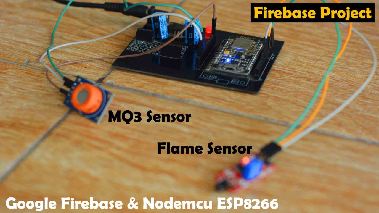
I have connected the MQ3 Gas sensor and Flame Sensor with my ESP8266 Development board as per the circuit diagram which I will explain in a minute.
As you can see I have powered up the ESP8266 and I have also opened my Google Firebase account.

Right now Nodemcu ESP8266 and Laptop are connected to the internet. Right now I am using the same WiFi network. But if you want you can also use different WiFi networks. It’s an IoT “Internet of things” based project. You can monitor your sensors from any part of the world, obviously if the internet connection is available.
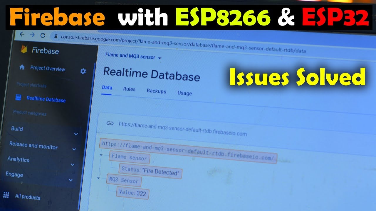
I have created this Realtime Firebase Database with the name Flame and MQ3 Sensor. This realtime Firebase database receives sensors values from the Nodemcu ESP8266 and displays the values over here. I am using digital mode of the Flame sensor, in the digital mode, the output of the flame sensor can be either 1 or 0. So, if no flame is detected then the message “No Fire” is printed and if the Flame is detected then the message “Fire Detected” is printed.
While I am using Analog mode of the MQ3 sensor. You will see different values depending on the amount of Gas leakage. Anyway, let’s go ahead and start the testing.

When the flame sensor detected the fire the status of the Flame sensor on the Google Firebase changed to “Fire Detected”.
Then I also tested the MQ3 Sensor and the value on the Firebase changed to 392. For the practical demonstration watch the video tutorial given at the end of this article.

I am sure by now, you might have got an idea of how does this system work. So, without any further delay let’s get started!!!
Amazon Links:
ESP32 WiFi + Bluetooth Module (Recommended)
Disclosure: These are affiliate links. As an Amazon Associate I earn from qualifying purchases.
Flame sensor:

This is the Flame Sensor Module which is also known as the Infrared IR Fire Sensor Detector. This Flame Sensor is extremely sensitive to IR wavelengths between 760-1100nm light. This flame sensor is ideal for short-range fire detection and can be used to monitor projects or as a safety precaution to cut devices OFF / ON or to turn ON buzzers or Send SMS. It can be used in hundreds of projects. I have found that this Flame Sensor is mostly accurate up to about 3 feet. I think this much range is enough.
Flame Sensor Specifications and Pinout:
On the right we have a black IR LED sensor. The Flame Sensor Module has a total of 4 male headers on the left side which are clearly labeled as
- A0 which is the Analog output pin of the Flame Sensor
- G this is the ground pin and it should be connected with the ground pin of the power supply or the Arduino board.
- + pin the input supply pin and this is where we connect 3.3v or 5v from the Arduino Board.
- D0 is the digital output signal pin which can be connected with any i/o pin of the Arduino board or it can be directly connected with TTL supported circuits for directly controlling the buzzers and relays etc.
This Flame sensor module is also provided with a Potentiometer which can be used for adjusting the Fire Flame detection sensitivity. The Flame sensor module is also provided with two LEDs L1 and L2. One LED is turned ON when you power up the Flame Sensor module while the other LED only lights up when it detects the flame.
Specifications:
- The working voltage: 3.3V-5V
- The output format: DO digital switching outputs (0 and 1) and AO analog voltage output
- Comparator: wide voltage LM393
- Length: 4.5cm / 1.77in
- Weight: 4g
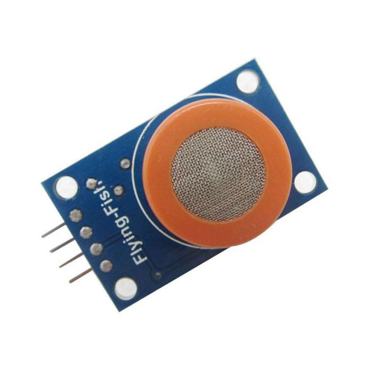
MQ3 Gas sensor:
Features:
- Double panel design, with power indicator and TTL output signal.
- Have DO switch signal (TTL) output and AO analog signal output.
- TTL output signal for low level effectively. (when the low output electric signal lights at ordinary times, can be directly connect single chip microcomputer or relay module)
- Analog output voltage with concentration, the higher concentration, the higher voltage.
- Has better sensitivity with the liquefied petroleum gas, natural gas, city gas, smoke.
- Has long service life and reliable stability
- Rapid response recovery features
Specifications:
- Input voltage: DC5V
- Power consumption (current) : 150 mA
- DO output: TTL digital 1 and 0 (0.1 and 5 V)
- AO output: 0.1-0.3 V
- Highest concentration of voltage: Approx 4 V
- Detection range of alcohol: detection range of 10 ~ 1000 PPM
Connection mode:
- VCC: Positive (5 v)
- GND: Connect power negative
- DO: TTL switch signal output
- AO: Analog signal output
Firebase ESP8266, Circuit Diagram:
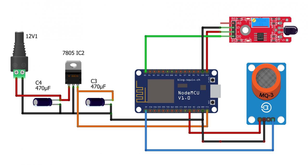
The power supply pins of MQ3 Sensor and Flame Sensor are connected with the 3.3V and GND pins of the Nodemcu ESP8266 WiFi module. The digital output pin D0 of the Flame sensor is connected with the D0 pin on the Nodemcu module. While the Analog output pin of the MQ3 Sensor is connected with the A0 analog pin of the Nodemcu ESP8266 WiFi module.
For the initial testing, you don’t need this 5V regulated power supply, you can use your laptop to power up the Nodemcu module. But if you are thinking about its practical implementation then you will need an external power supply. Now, let’s go ahead and start working on the Google Firebase.
Google Firebase Database setup:
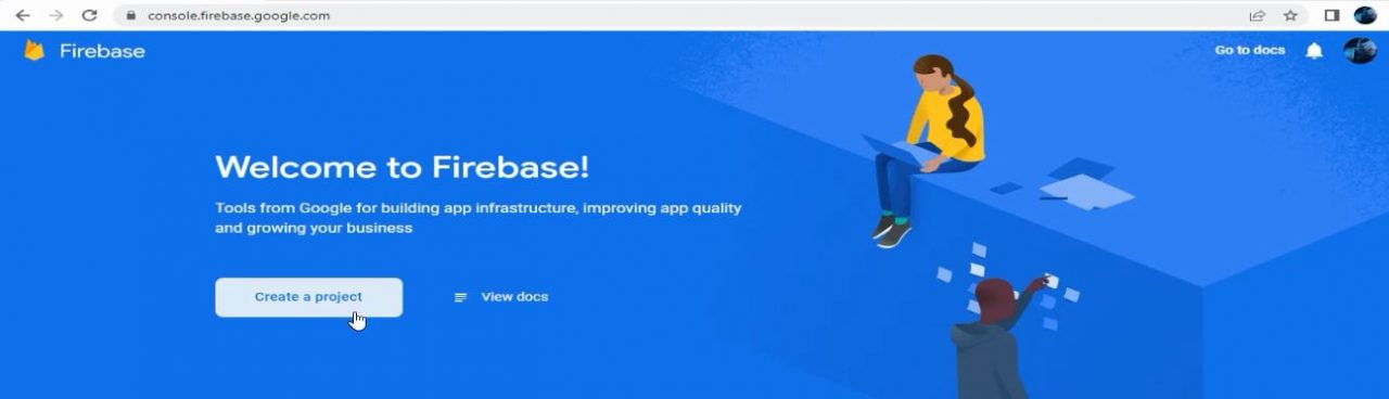
Search for the Firebase and click on the first link

Next, click on Go to console.

Next, click on Create a project.
Enter the Project name, in my case, I am going to select “Flame and MQ3 sensor” avoid long project names. Check the boxes to confirm the Firebase terms and click on the Continue button.

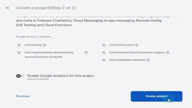
Disable the Google Analytics for this project and click on the Create project button.
Once your project is ready click on the Continue button. This step may take a minute or so. Now, click on the Authentication.
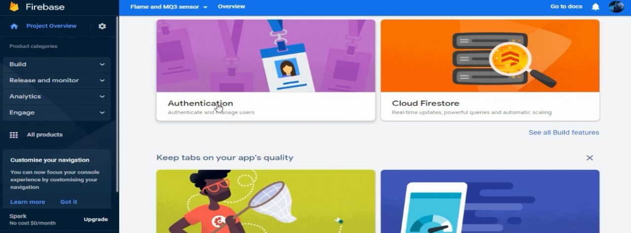
Click on Get started.

Then in Sign-in provider click on Anonymous.

Click on Enable and save the changes.
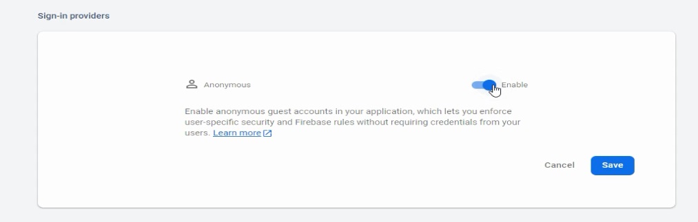
After you click on the save button, on the next page you will see the Status is now changed to Enabled.
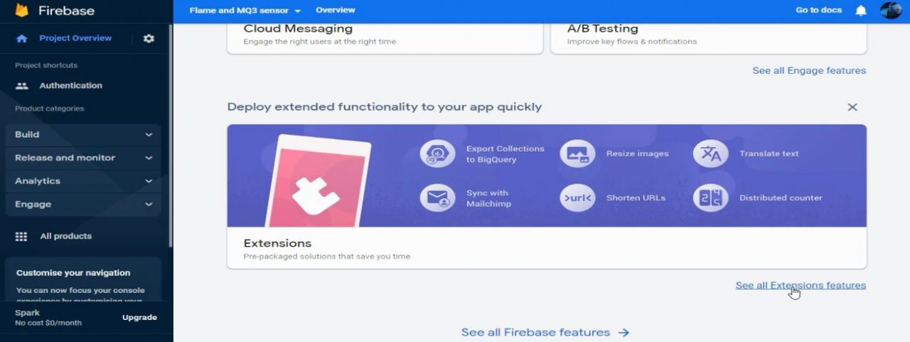
Now, click on the Project Overview on the left side. Scroll down and click on the See all Extensions features.
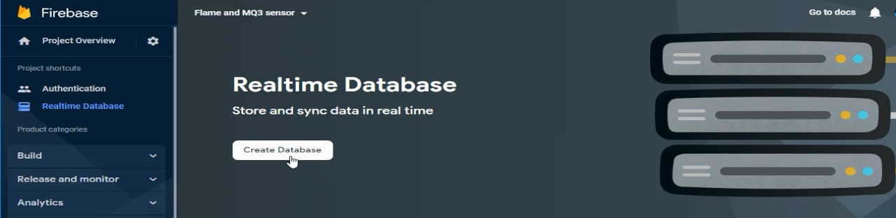
Scroll down and select Realtime Database.

Click on Create Database.
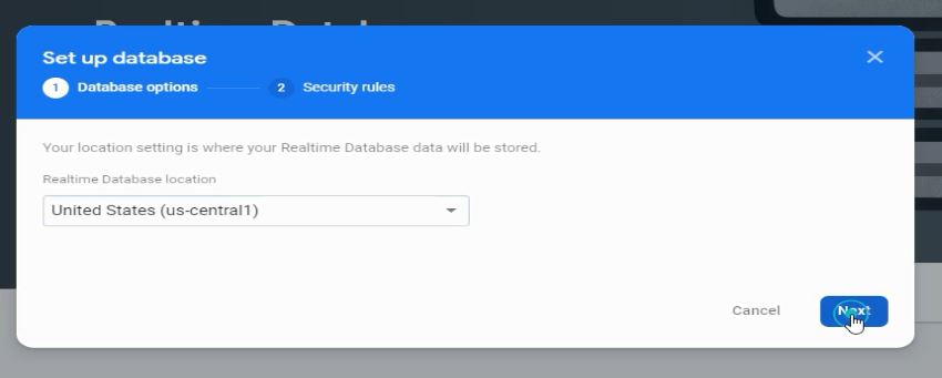
While the United States selected, click on the Next button.
Select Start in test mode and click the Enable button.

Copy this link.

Open the programming file and paste this link next to the DATABASE_URL.

Now, open the Project settings.

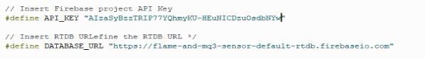
Copy the Web API key.

Again open the programming file and paste it next to the API_KEY.
We are done with all the settings, Now, I can click on the Realtime Database and start monitoring my Sensors. Now, let’s go ahead and take a look at the programming.
ESP8266 Board Manager & Library:
If you have never used the Nodemcu ESP8266 WiFi module, then I highly recommend that you guys should read my getting started article on the Nodemcu ESP8266, in that article I have explained how to install the ESP8266 board manager URL link. If you do not install the ESP8266 board then you won’t be able to find the NodeMCU ESP8266 in the boards list in the Arduino IDE. So, installing the ESP8266 board is the first thing that you have to do.
After you are done with installing the ESP8266 or ESP32, now, In order to connect your Google Firebase Database account with the Nodemcu ESP8266 or ESP32 you will need this Firebase_ESP_Client library. To install this library, simply click on the Sketch menu, then Include Library, and click on the Manage Libraries.
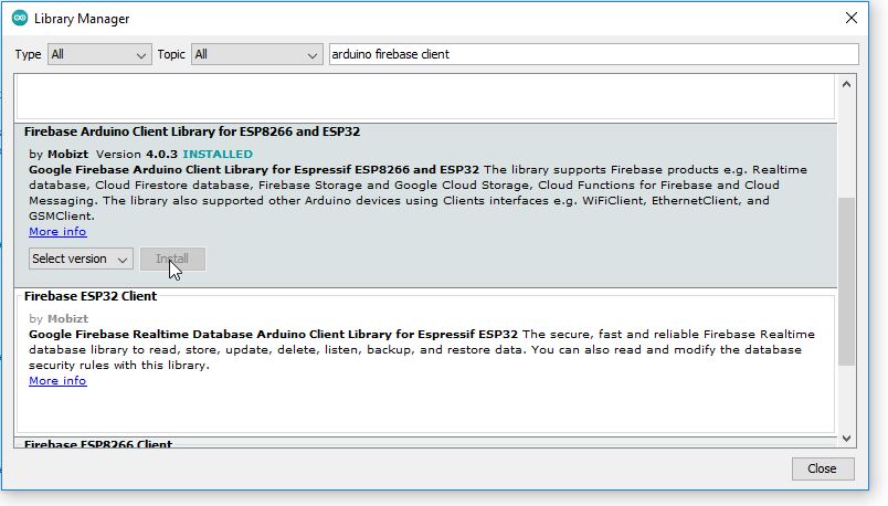
Search for the firebase Arduino. As you can see I have already installed the Firebase Arduino Client Library for ESP8266 and ESP32.
Firebase ESP8266, Programming:
|
1 2 3 4 5 6 7 8 9 10 11 12 13 14 15 16 17 18 19 20 21 22 23 24 25 26 27 28 29 30 31 32 33 34 35 36 37 38 39 40 41 42 43 44 45 46 47 48 49 50 51 52 53 54 55 56 57 58 59 60 61 62 63 64 65 66 67 68 69 70 71 72 73 74 75 76 77 78 79 80 81 82 83 84 85 86 87 88 89 90 91 92 93 94 95 96 97 |
#include <Arduino.h> #if defined(ESP32) #include <WiFi.h> #elif defined(ESP8266) #include <ESP8266WiFi.h> #endif #include <Firebase_ESP_Client.h> //Provide the token generation process info. #include "addons/TokenHelper.h" //Provide the RTDB payload printing info and other helper functions. #include "addons/RTDBHelper.h" // Insert your network credentials #define WIFI_SSID "AndroidAP3DEC" #define WIFI_PASSWORD "electroniclinic" // Insert Firebase project API Key #define API_KEY "AIzaSyBzzTRIP77YQhmyKU-HEuNICDzuOsdbNYw" // Insert RTDB URLefine the RTDB URL */ #define DATABASE_URL "https://flame-and-mq3-sensor-default-rtdb.firebaseio.com" //Define Firebase Data object FirebaseData fbdo; FirebaseAuth auth; FirebaseConfig config; unsigned long sendDataPrevMillis = 0; bool signupOK = false; int fsensor=D0; int mq3sensor=A0; int sensorvalue; String firestatus=""; void setup(){ Serial.begin(115200); pinMode(fsensor, INPUT);//define F_Sensor input pin pinMode(mq3sensor, INPUT);//MQ3 sensor WiFi.begin(WIFI_SSID, WIFI_PASSWORD); Serial.print("Connecting to Wi-Fi"); while (WiFi.status() != WL_CONNECTED){ Serial.print("."); delay(300); } Serial.println(); Serial.print("Connected with IP: "); Serial.println(WiFi.localIP()); Serial.println(); /* Assign the api key (required) */ config.api_key = API_KEY; /* Assign the RTDB URL (required) */ config.database_url = DATABASE_URL; /* Sign up */ if (Firebase.signUp(&config, &auth, "", "")){ Serial.println("ok"); signupOK = true; } else{ Serial.printf("%s\n", config.signer.signupError.message.c_str()); } /* Assign the callback function for the long running token generation task */ config.token_status_callback = tokenStatusCallback; //see addons/TokenHelper.h Firebase.begin(&config, &auth); Firebase.reconnectWiFi(true); } void loop(){ if (Firebase.ready() && signupOK && (millis() - sendDataPrevMillis > 5000 || sendDataPrevMillis == 0)){ sendDataPrevMillis = millis(); // Write an Int number on the database path test/int int fire = digitalRead(fsensor);// read Flame sensor if( fire == HIGH) { firestatus="Fire Detected"; Firebase.RTDB.setString(&fbdo, "Flame sensor/Status", firestatus); Serial.println("Fire Detected"); } else { firestatus="No Fire"; Firebase.RTDB.setString(&fbdo, "Flame sensor/Status", firestatus); Serial.println("No Fire"); } sensorvalue=analogRead(mq3sensor); /// read the MQ3 sensor Serial.println(sensorvalue); Firebase.RTDB.setFloat(&fbdo, "MQ3 Sensor/Value",sensorvalue); } } |
Watch Video Tutorial on YouTube
Discover more from Electronic Clinic
Subscribe to get the latest posts sent to your email.