Arduino IoT Cloud Getting Started Tutorial using ESP32
Table of Contents
Arduino IoT Cloud, Description:
Arduino IoT Cloud Getting Started Tutorial using ESP32- I have been using different IoT platforms including Ubidots, Thingspeak, and Blynk application for remote Sensors monitoring and for controlling different electrical devices. Today for the first time I am going to use the Arduino IoT cloud, so basically this is going to be a getting started tutorial explaining how to use the Arduino IoT Cloud with the ESP32 WiFi + Bluetooth module. To be very fair with you guys, the Arduino IoT cloud is not as powerful as the Blynk application and Ubidots but you can use the Arduino IoT cloud as the Alternative because it’s very easy to use as compared to the other IoT platforms and moreover the Arduino IoT Cloud is becoming very popular and I am sure they will be adding more widgets and features in the future. Anyways with the Arduino IoT cloud, you can monitor and control anything you want but there is a limit which I will explain later in this article.
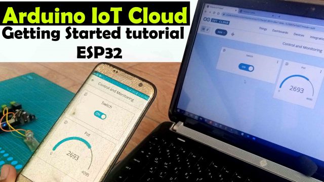
In this tutorial, we will write a very basic program to control the ESP32 onboard LED, and then we will modify the code to monitor an analog sensor, for demonstration purposes I have used a Potentiometer. The very best thing about the Arduino IoT Cloud is that when you make the dashboard on your PC the Android or IOS App is automatically generated and then you can monitor and control things from your cell phone.
Without any further delay let’s get started!!!
Amazon Links:
ESP32 WiFi + Bluetooth Module(Recommended)
Other Tools and Components:
Super Starter kit for Beginners
PCB small portable drill machines
*Please Note: These are affiliate links. I may make a commission if you buy the components through these links. I would appreciate your support in this way!
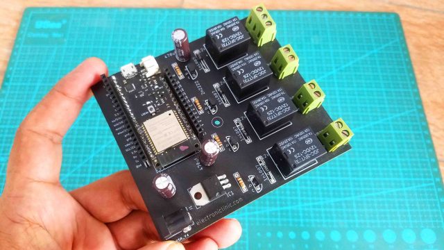
You can use the ESP32 WiFi + Bluetooth module alone or you can use my designed ESP32 development board. This is the same board I used in ESP32 Home automation, IoT Water level Monitoring system, and IoT pH meter.
In the first example we will control the ESP32 onboard LED which is connected with the GPIO5, different versions of the ESP32 modules have onboard LEDs connected with different pins. The one I am using has its LED connected with GPIO5. Now let’s setup the Arduino IoT Cloud.
Altium Designer:
Altium Designer is the world’s most trusted PCB design system. Altium Designer enables engineers to effortlessly connect with every facet of the electronics design process. Over 35 years of innovation and development focused on a truly unified design environment makes it the most widely used PCB design solution. With Altium Designer you can create PCB designs with an intuitive and powerful interface that connects you to every aspect of the electronics design process. Route it your way through any angle, tune for delay, Push, Slide, and Walkaround faster than ever. Interact and collaborate with mechanical designers like never before in a photo-realistic, 3D design environment. If you want to get started with the Altium designer, you can click on the get started.
Arduino IoT Cloud Setup:
Open Google on your internet browser and search for the Arduino IoT cloud.
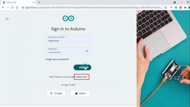
Click on the Create one if you are not registered, I have already created my account so I will simply enter my username and password and finally I will click on the SIGN IN button. After clicking on the Sign in button the page will be opened where the user is asked to activate the 2 step verification.
You can also protect your account with 2-step verification which is something you are already quite familiar with; I am going to skip this.
That’s it; our Arduino IoT cloud account is ready.
let’s take a look at different Plans before we create our first Thing. Click on the UPGRADE PLAN button on the top right side of the page.
We have these 4 Monthly and Yearly Plans, As a beginner you can start with the FREE Plan and then if you like it you can try other PLANS. As a beginner free plan is not bad at all you can create 2 Things, Unlimited dashboards, 100 Mb to store sketches, 1 day data retention, and nice compilation time. I myself using the FREE plan, you can compare FREE Plan with the other three plans and select the one as per your requirement, enough with the talking now let’s go ahead and create our first Thing.
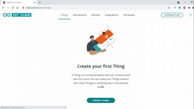
Go back to the previous page and click on the Create Thing button.
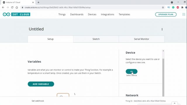
Click on the Select Device button and then Click on the SET UP NEW DEVICE and then Click on the Set up a 3rd Party device.
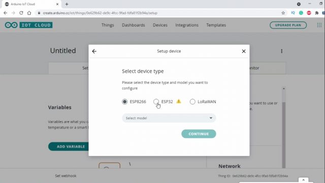
Select the device and model, on the select model drop down menu you can select ESP32 Dev Module and then click on the Continue button. On the next page, give your device a name.
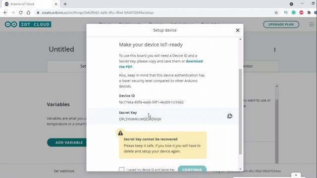
Never share this information with anyone, we will need the Device ID and the Secret Key later, I highly recommend to download the PDF file. Then you can scroll down, check the box, and click on the CONTINUE Button.
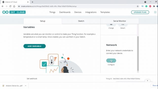
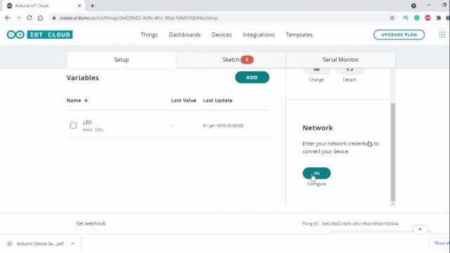
Now scroll down and you can see the Network. You can see the Configure button is disabled, this will become enable after adding at least one variable, so let’s add a variable, for this click on the ADD VARIABLE Button. type the variable name, in my case LED, Select the variable type, in my case, I will select Boolean type because the LED can have only two states High or Low, I am not controlling the brightness.
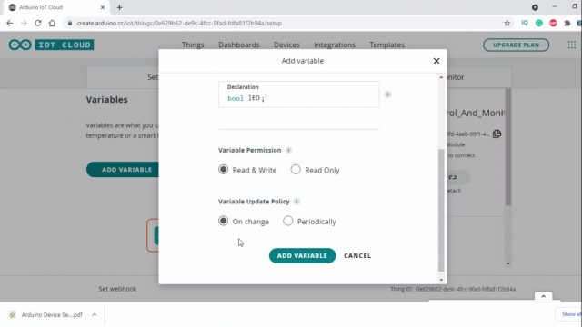
In the variable permission select Read & Write and in the Variable Update Policy select On Change, as I will be using a button to control the ESP32 Onboard LED. So, our variable is setup and now we can click on the ADD VARIABLE Button. The variable will be added.
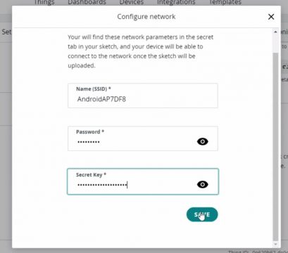
Now, if we go to the Network, we can see the Configure button is now enabled and now we can enter our WiFi credentials. The secret key we will copy from the PDF file.
Now we are ready for the programming.
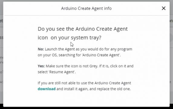
The sketch will be automatically updated, the variable LED that we added will be automatically added. When you first click on the sketch you will get this message “To upload a Sketch via a USB port, make sure the Create Agent is installed and running on this computer”. If this ArduinoCreateAgent is not installed then you won’t be able to upload the code. Click on the learn more.
Read the text and then click on the download button to download and install the ArduinoCreateAgent, Open the ArduinoCreateAgent and follow the onscreen instructions. Click on the sketch and you will see the lED variable near to the top and the onLEDChange() function at the bottom of the sketch, these two are automatically added.
Now to write our code to control an LED let’s open the full editor. While you are still on the sketch scroll up until you see the open full editor button. Select your board type. I started off by defining the pin to which the onboard LED is connected.
|
1 |
<span style="font-size: 18pt; font-family: 'times new roman', times, serif;">int myled = 5;</span> |
Next, in the setup() function I set the led as the output device using the pinMode() function.
|
1 |
<span style="font-size: 18pt; font-family: 'times new roman', times, serif;">pinMode(myled, OUTPUT);</span> |
Finally, in the onLEDChange() function I added an if condition to check if the button is pressed or not, if the button is pressed then turn ON the LED else turn OFF the LED.
|
1 2 3 4 5 6 7 8 9 |
<span style="font-size: 18pt; font-family: 'times new roman', times, serif;">void onLEDChange() { // Do something if(lED) digitalWrite(myled,LOW); else digitalWrite(myled, HIGH); } </span> |
Arduino IoT Cloud Dashboards:
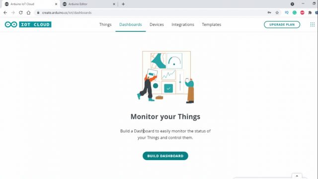
Now open the Dashboards page to add a button and link the variable. Click on the Build Dashboard button.
Set the dashboard name, I chose Control and Monitoring. Now you can click on the Add button to add a switch to the Dashboard. On the Widget Settings, you can set the name, and then you can click on the Link variable button to select the variable that we created before “LED”.
Our dashboard is ready. Again I opened the program, compiled the code, and finally, I uploaded the code. You can use this button to control the LED. For The practical demonstration watch video tutorial given at the end of this article.
Arduino IoT Cloud Analog Sensor Monitoring:
Now, for this next example I have connected the middle leg of the potentiometer with the GPIO pin 35 and the other two legs of the potentiometer with the 3.3V and GND.
Now to add a variable for the Potentiometer click on the Things and follow the same exact steps as we did for the LED, but this time as we are monitoring a sensor so we will set the variable to the read only, I have explained everything in the video. I have explained how to modify the code and how to add the Gauge.
Control and Monitoring, Final Code:
|
1 2 3 4 5 6 7 8 9 10 11 12 13 14 15 16 17 18 19 20 21 22 23 24 25 26 27 28 29 30 31 32 33 34 35 36 37 38 39 40 41 42 43 44 45 46 47 48 49 50 51 52 53 54 55 56 57 58 59 60 61 62 |
<span style="font-size: 14pt; font-family: 'times new roman', times, serif;">/* Sketch generated by the Arduino IoT Cloud Thing "Untitled" https://create.arduino.cc/cloud/things/0e629b62-de9c-4fcc-9fad-fdfa81f2b94a Arduino IoT Cloud Variables description The following variables are automatically generated and updated when changes are made to the Thing int potentiometer; bool lED; Variables which are marked as READ/WRITE in the Cloud Thing will also have functions which are called when their values are changed from the Dashboard. These functions are generated with the Thing and added at the end of this sketch. */ #include "thingProperties.h" int myled = 5; int pot = 35; void setup() { // Initialize serial and wait for port to open: Serial.begin(9600); pinMode(myled, OUTPUT); pinMode(pot,INPUT); // This delay gives the chance to wait for a Serial Monitor without blocking if none is found delay(1500); // Defined in thingProperties.h initProperties(); // Connect to Arduino IoT Cloud ArduinoCloud.begin(ArduinoIoTPreferredConnection); /* The following function allows you to obtain more information related to the state of network and IoT Cloud connection and errors the higher number the more granular information you’ll get. The default is 0 (only errors). Maximum is 4 */ setDebugMessageLevel(2); ArduinoCloud.printDebugInfo(); } void loop() { ArduinoCloud.update(); // Your code here potentiometer = analogRead(pot); } void onLEDChange() { // Do something if(lED) digitalWrite(myled,LOW); else digitalWrite(myled, HIGH); } </span> |
We have just built a two way communication system using ESP32 and Arduino IoT Cloud, we can monitor the sensor and control the Onboard LED at the same time. Now one last step, if it’s hard for you to use your laptop for controlling and monitoring, then you can use the IoS and Android cell phone App. You will need to download the Arduino IoT Cloud Remote App from the Play Store. You don’t need to do anything, this app is automatically generated and this is the best thing I like about the Arduino IoT Cloud as compared to the Blynk.
