ESP32 pH Sensor, IoT pH Sensor Code and Circuit diagram
Table of Contents
ESP32 pH Sensor, Description:
ESP32 pH Sensor– I have been using pH Sensor with Arduino and Nodemcu ESP8266 for measuring the pH value of different liquids. I also used it with the EC Sensor or TDS sensor for measuring the Water Quality and I also used it in the making of a low-cost Hydroponics system which was an Arduino based project. As explained in my previous tutorial which is based on the IoT Water level monitoring system using ToF10120 Laser Rangefinder or Distance senor, I am writing this series of articles to explain how to use each sensor individually before I make the complete IoT based Hydroponics system.
So, in this series of articles, my first article was based on the IoT Water level monitoring system using ESP32, ToF10120, and Blynk application. In this article, I explained each and every detail including interfacing, programming, and how to get rid of the fluctuations.
In today’s tutorial, which is the 2nd article in this series, I am going to explain how to make IoT pH Sensor using the pH sensor kit from the DiyMore, ESP32 WiFi + Bluetooth module, I2C supported Oled display module, and Blynk application. The pH sensor kit from the Diymore is a bit different from the one designed by DFrobot which I have also used in some of my previous tutorials explaining what is a pH sensor, it’s working, Calibration, and how to use a pH sensor to find the pH value of different liquids. I also used the DFrobot pH sensor kit for measuring the water quality using the Arduino board and I also used it in an IoT based water quality monitoring system using the NodeMCU ESP8266 WiFi module.
The Diymore pH sensor kit is cheap as compared to the DFrobot pH sensor kit. I have already explained how to calibrate and use this low-cost pH sensor kit with the Arduino to measure the pH value of different liquids, so I highly recommend first read my previous articles and then you can resume from here, because I will use the same code, but I will do some modifications to make it compatible with the ESP32 WiFi + Bluetooth Module. Anyways, after modifying the code and interfacing the pH Sensor and Oled Display module with the ESP32 Development board, finally I was ready to test the pH Value of different liquids including Water, Acidic solution, and washing powder. Before, I am going to share with you the test results, first, a few words about the sponsor of this project.
Altium Designer:
Altium Designer is the world’s most trusted PCB design system. Altium Designer enables engineers to effortlessly connect with every facet of the electronics design process. Over 35 years of innovation and development focused on a truly unified design environment makes it the most widely used PCB design solution. With Altium Designer you can create PCB designs with an intuitive and powerful interface that connects you to every aspect of the electronics design process. Route it your way through any angle, tune for delay, Push, Slide, and Walkaround faster than ever. Interact and collaborate with mechanical designers like never before in a photo-realistic, 3D design environment. If you want to get started with the Altium designer, you can click on the get started.
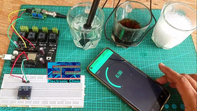
I have already calibrated my pH sensor kit the same way as I explained in my previous article. Initially I started with the water, I waited for a few minutes to let the pH Sensor stabilize.
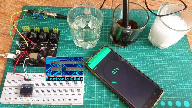
The Water pH value which you can see on the Oled display module is simply amazing, you know The pH of most drinking-water lies within the range 6.5 and 8.5. Natural waters can be of lower pH. The water under test is from Well and the value fluctuates around 7, which means this water is drinkable. I am pretty satisfied with the result. The same value you can also see on the Blynk application. So, no matter where you are, if you have access to the internet, then you can monitor the pH value of any liquid from anywhere in the world. How easy it is to make an IoT pH sensor using just a few low-cost electronics components. Anyways next I am going to check the pH value of this Acidic solution.
This is amazing, the pH sensor is working just fine, a lower pH value means the solution is very acidic. Next, I am going to test the pH value of washing powder.
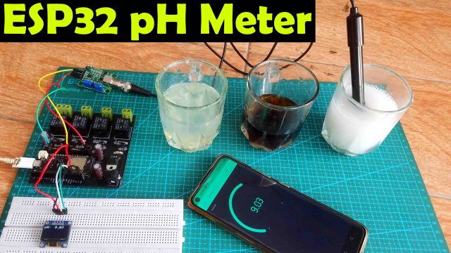
You know mostly the powder detergents pH value is close to 10, you may get a slightly lower value or a high value depending on the chemicals used. I shared the test results with you guys and now you have got the idea of what you are going to learn after reading this article. Without any further delay let’s get started!!!
Note: this old version of the Blynk app is no more functional. For the blynk mobile App setup and Blynk.cloud dashboard setup ready my article on the New Blynk V2.0. In this article I have explained how to migrate your projects from Blynk 1.0 to the new Blynk V2.0. You can also watch the video.
Amazon Links:
ESP32 WiFi + Bluetooth Module(Recommended)
128×64 SSD1306 Oled display Module
Other Tools and Components:
Super Starter kit for Beginners
PCB small portable drill machines
*Please Note: These are affiliate links. I may make a commission if you buy the components through these links. I would appreciate your support in this way!
IoT pH Sensor Circuit Diagram:
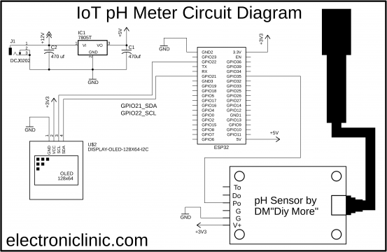
On the top left side you can see a regulated 5v power supply which is used to supply 5 volts to the ESP32 Module. If you want to use an external power source then you will need this power supply and you will need to connect a wire from the output of 7805 regulator with the 5v pin of the ESP32 WiFi + Bluetooth Module. The main advantage of using this regulated 5v power supply is that, you can power up your ESP32 module using a 12v adaptor or a solar panel. But if you are performing basic experiments then you can use your Laptop or computer to power up the ESP32 Module.
The Oled display module power supply pins are connected with the 3.3V and GND pins while the SDA and SCL pins are connected with the GPIO pins 21 and 22.
The pH sensor kit V+ and GND pins are connected with the 3.3V and GND while the Po pin which is the analog output pin is connected with the GPIO pin 35.
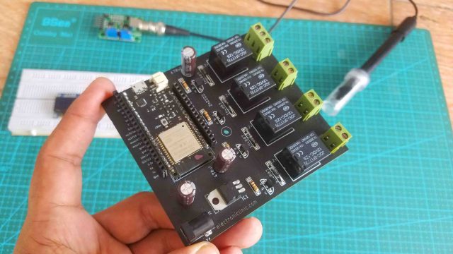
This is the same ESP32 development board which I used with the TOF10120 Sensor, so I am going to use the same board with the pH sensor kit and Oled display module. You can see this board also has the relays, but for now I am not using these relays. If you want to make the same ESP32 Development board then you can read my article on the IoT Home Automation project.
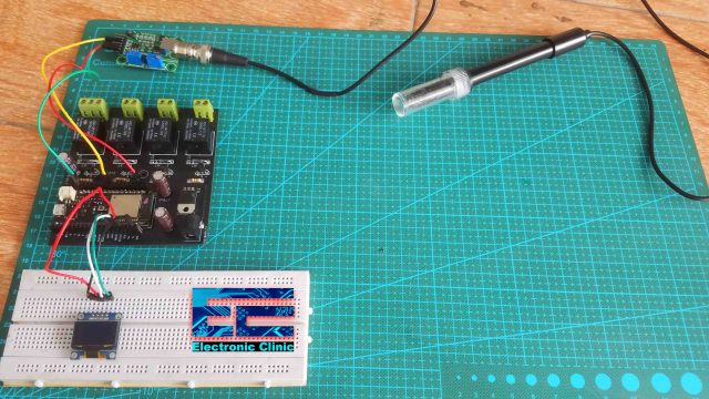
Anyway, I connected the I2C supported Oled display module and the pH sensor kit with the ESP32 as per the circuit diagram which I just explained. So, my interfacing is completed and now let’s take a look at how to make the Blynk application.
Blynk Application making:
Blynk application isn’t difficult at all, just a few steps and you are done. For the step by step explanation watch video tutorial given at the end of this article. Before, you start the programming first of all, make sure you download all the necessary libraries.
IoT ESP32 pH Sensor Programming:
|
1 2 3 4 5 6 7 8 9 10 11 12 13 14 15 16 17 18 19 20 21 22 23 24 25 26 27 28 29 30 31 32 33 34 35 36 37 38 39 40 41 42 43 44 45 46 47 48 49 50 51 52 53 54 55 56 57 58 59 60 61 62 63 64 65 66 67 68 69 70 71 72 73 74 75 76 77 78 79 80 81 82 83 84 85 86 87 88 89 90 91 92 93 94 95 96 97 98 99 100 101 102 103 104 105 106 107 |
//download libraries //https://www.electroniclinic.com/arduino-libraries-download-and-projects-they-are-used-in-project-codes/ #include <Wire.h> #include <Adafruit_GFX.h> #include <Adafruit_SSD1306.h> #include <BlynkSimpleEsp32.h> #include <SimpleTimer.h> // You should get Auth Token in the Blynk App. char auth[] = "3vbf7rpD6vqpvve23wX3LcgknUqh_L31"; // Your WiFi credentials. // Set password to "" for open networks. char ssid[] = "AndroidAP7DF8"; char pass[] = "electroniclinic"; SimpleTimer timer; float calibration_value = 20.24 - 0.7; //21.34 - 0.7 int phval = 0; unsigned long int avgval; int buffer_arr[10],temp; float ph_act; // for the OLED display #define SCREEN_WIDTH 128 // OLED display width, in pixels #define SCREEN_HEIGHT 64 // OLED display height, in pixels // Declaration for an SSD1306 display connected to I2C (SDA, SCL pins) #define OLED_RESET -1 // Reset pin # (or -1 if sharing Arduino reset pin) Adafruit_SSD1306 display(SCREEN_WIDTH, SCREEN_HEIGHT, &Wire, OLED_RESET); void setup() { Wire.begin(); Serial.begin(9600); Blynk.begin(auth, ssid, pass); display.begin(SSD1306_SWITCHCAPVCC, 0x3C); display.clearDisplay(); display.setTextColor(WHITE); timer.setInterval(500L, display_pHValue); } void loop() { Blynk.run(); timer.run(); // Initiates SimpleTimer for(int i=0;i<10;i++) { buffer_arr[i]=analogRead(35); delay(30); } for(int i=0;i<9;i++) { for(int j=i+1;j<10;j++) { if(buffer_arr[i]>buffer_arr[j]) { temp=buffer_arr[i]; buffer_arr[i]=buffer_arr[j]; buffer_arr[j]=temp; } } } avgval=0; for(int i=2;i<8;i++) avgval+=buffer_arr[i]; float volt=(float)avgval*3.3/4096.0/6; //Serial.print("Voltage: "); //Serial.println(volt); ph_act = -5.70 * volt + calibration_value; Serial.print("pH Val: "); Serial.println(ph_act); Blynk.virtualWrite(V2,ph_act); delay(1000); } void display_pHValue() { // display on Oled display // Oled display display.clearDisplay(); display.setTextSize(2); display.setCursor(0,0); // column row display.print("pH:"); display.setTextSize(2); display.setCursor(55, 0); display.print(ph_act); /* display.setTextSize(2); display.setCursor(0,30); display.print("EC:"); display.setTextSize(2); display.setCursor(60, 30); display.print(345); display.setCursor(95, 50); */ display.display(); } |
pH Meter Code Explanation:
This is the same exact code which I used in the getting started tutorial which was based on the Arduino board. But as this time I am using the ESP32 Board with the pH sensor Kit; So, I made a few changes, you can see in the code, I added libraries for the Blynk application, I also added the authentication token which was generated while making the Blynk application and I also added the WiFi credentials.
|
1 2 3 4 5 6 7 8 9 10 11 12 13 |
float volt=(float)avgval*3.3/4096.0/6; //Serial.print("Voltage: "); //Serial.println(volt); ph_act = -5.70 * volt + calibration_value; Serial.print("pH Val: "); Serial.println(ph_act); Blynk.virtualWrite(V2,ph_act); |
Another most important change is the voltage and the adc resolution and finally to send the value to the Blynk application I added this “ Blynk.virtualWrite(V2,ph_act);” line of code and you can see I am using the same V2 virtual pin and the final pH value. Everything else remains exactly the same. So, that’s all for now.
Don’t forget to like and subscribe to my YouTube channel, Electronic Clinic.
Watch Video Tutorial:


Hi, may I know what the usage of multiply of -5.7 on voltage.
Thanks