TDS meter Arduino, water Quality monitoring Project, TDS in Water
Last Updated on August 18, 2024 by Engr. Shahzada Fahad
Table of Contents
TDS meter Arduino Project Description:
TDS meter Arduino, water Quality monitoring Project, TDS in Water– Declining water Quality has become a global issue of concern as human populations grow, industrial and agricultural activities expand, and climate change threatens to cause major alterations to the Hydrological cycle. Every year, more people die from unsafe water than from all forms of violence, including war.
Have you ever tried to find out what is the pH value and TDS value of the water you are drinking? Using a pH sensor and a TDS Sensor you can make a perfect water quality monitoring system. I have already used the pH sensor with Arduino and Nodemcu esp8266 wifi Module for measuring the water quality.
Arduino and pH Sensor getting started tutorial.
Nodemcu ESP8266 Wifi Module and pH Sensor-based Water quality monitoring.
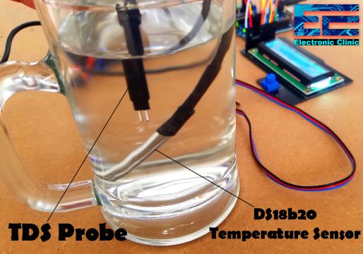
In this tutorial, you will learn how to make a water quality monitoring system using the Gravity TDS Meter V1.0, DS18B20 Waterproof one-wire digital temperature sensor, and 16×2 LCD with Arduino for measuring the TDS value. TDS stands for Total Dissolved Solids.

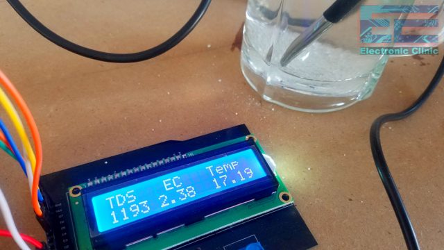
The TDS in water value as you can see on the LCD screen indicates how many milligrams of soluble solids are dissolved in one liter of water. Many TDS meters display the TDS value in ppm which stands for parts per million. In general, the higher the TDS value, the more soluble solids are dissolved in water, and the less clean the water is. Right now the water under test is excellent as the TDS value is less than 300.
During the experiment, I added the Salt to check if the TDS value will increase.
The TDS value starts increasing as I started adding the salt. So, using this small DIY low-cost TDS meter you can find out if the water you are drinking is clean or not.
Along with the TDS value, you can also see the EC and temperature values which I will explain in a minute. I will also explain what TDS value is good for drinking water? I will explain all the three parameters in detail.
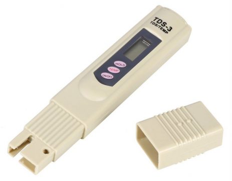
You can also use a TDS pen which is quite cheap and can be used for measuring the TDS value. But, if you are planning to make a hydroponic system that maintains a certain ph level then the TDS pen will never work. Because for the hydroponic systems; you will need an automatic system that can turn on and turn off other electrical devices. Moreover, you cannot use this TDS pen in IOT based projects.
But this TDS Meter can be used in automatic Hydroponic and IOT based water quality monitoring systems. For the practical demonstration watch video given at the end of this article.
Without any further delay let’s get started!!!
Amazon Links:
Arduino Nano USB-C Type (Recommended)
DS18B20 one-wire digital temperature sensor:
*Disclosure: These are affiliate links. As an Amazon Associate I earn from qualifying purchases.
About the Gravity TDS Meter V1.0:
This is the Gravity TDS Meter V1.0 Analog Sensor kit by the DFrobot which is completely compatible with Arduino. One thing that I really like about this TDS Meter is that it supports 3.3 to 5.5 Volts wide voltage input, and 0 to 2.3 Volts analog voltage output, which makes this TDS meter compatible with 5V and 3.3V control systems or boards. This comes with the plug and play type TDS probe which is waterproof and can be immersed in water for long-time measurement. This board has a working current of 3 to 6mA. The TDS measurement Range is from 0 to 1000 ppm. While the measurement accuracy is ±10% at 25 degrees centigrade.
While using this TDS meter you have to be careful, the probe cannot be used in water above 55 degrees centigrade.
The probe cannot be left too close to the edge of the container; otherwise, it will affect the reading.
The head and the cable of the probe are waterproof, but the connector and the signal transmitter board are not waterproof, so be careful while using this TDS meter Analog Sensor kit.
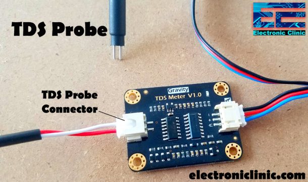
TDS Meter Pin Description/Pinout:

As you can see this Signal Transmitter Board has two connectors. The left one is the TDS Probe Connector and the right side connector is used to interface this module with the Arduino or any other compatible controller board. The connector pins are labeled with A which is the analog output pin and should be connected with the analog pin of the Arduino, + which can be connected with 3.3 or 5 volts, and – which is the ground pin.
Before I am going to explain the circuit diagram and programming, first I am going to explain some basic things, which I believe you should know.
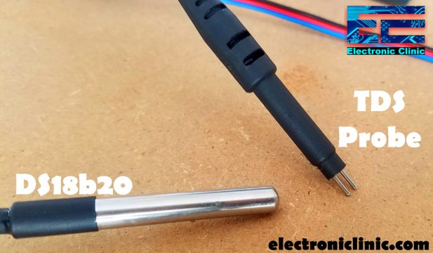
This TDS probe has no temperature sensor, So that’s the reason I am using the DS18B20 waterproof one-wire digital temperature sensor for the temperature compensation, this is important for the accurate values. Although the temperature compensation algorithm is reserved in the sample code the default value is 25 degrees centigrade. But I highly recommend use a temperature sensor if you want accurate values.
0 ppm is considered the most ideal result. TDS meters cannot detect non-ionic particles like sugar and will not contribute to the reading. This can be practically seen in the video given at the end of this article.
This TDS meter is based on the EC “electrical conductivity and 1 EC equal approximately 900 ppm. The EC of most other metals, minerals, and salts will carry a charge. A TDS meter measures that EC level and then converts it to a TDS measurement.
You might be thinking what TDS value is good for drinking water?
Water is considered excellent if it’s less than 300 mg/liter,
water is considered good if it’s between 300 and 600 mg/litre.
Water is considered fair if it’s between 900 and 1200 mg/litre.
Water is considered unacceptable if the value is greater than 1200mg/litre.
As per the TDS regulation, the U.S. EPA sets the maximum contaminant level for TDS at 500 ppm. The World Health Organization (WHO) sets the maximum contaminant for TDS at 1000 ppm.
Circuit Diagram:

A TDS probe is connected with the Signal Transmitter Board. The analog output pin of the TDS meter is connected with the Arduino’s analog pin A1. + pin of the TDS Meter is connected with the Arduino’s 5 volts, while the minus “-“ pin is connected with the Arduino’s ground.
Pin number1 and pin number 16 are connected with the Arduino’s ground. Pin number 2 and pin number 15 are connected with the Arduino’s 5 volts. Pin number 3 is the contrast pin of the 16×2 LCD and is connected with the middle leg of the Variable resistor or Potentiometer. While the other two legs of the variable resistor are connected with the Arduino’s 5 volts and ground. The RS pin of the LCD is connected with the Arduino’s pin number 10, the R/W pin is connected with the ground, the enable pin is connected with the Arduino’s pin number 9. The data pins D4 to D7 of the LCD are connected with the Arduino’s pin number 6, 5, 4, and 3.
As you can see a 330-ohm resistor is connected between the VCC and data wires. You can also use a 4.7k resistor. The data pin is connected with the Arduino’s pin number 7. The VCC is connected with 5 volts, while the ground is connected with the Arduino’s ground.
About the PCB boards and PCBWay:

The PCB boards used in this project are sponsored by the PCBway Company, which is one of the most experienced PCB and PCB assembly manufacturer. They create high-quality PCBs at reasonable prices. As you can see the quality is really great, the silkscreen is quite clear the black and blue solder mask looks amazing. I am 100% satisfied with their work.
Gerber files:
High quality & Only 24 Hours Build time
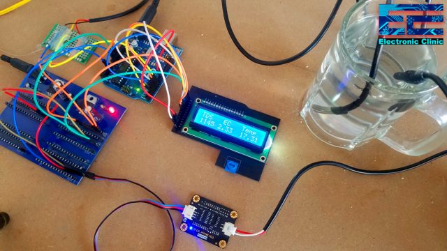
TDS Meter and 16×2 LCD Interfacing with Arduino:
All the connections are done as per the circuit diagram already explained. The power supply board is used to distribute the 5V and ground wires.
TDS Meter Arduino Programming:
|
1 2 3 4 5 6 7 8 9 10 11 12 13 14 15 16 17 18 19 20 21 22 23 24 25 26 27 28 29 30 31 32 33 34 35 36 37 38 39 40 41 42 43 44 45 46 47 48 49 50 51 52 53 54 55 56 57 58 59 60 61 62 63 64 65 66 67 |
#include <OneWire.h> #include <DallasTemperature.h> #include <LiquidCrystal.h> // 16x2 LCD #define rs 10 #define en 9 #define d4 6 #define d5 5 #define d6 4 #define d7 3 // initialize the library with the numbers of the interface pins LiquidCrystal lcd(rs, en, d4, d5, d6, d7); namespace pin { const byte tds_sensor = A1; const byte one_wire_bus = 7; // Dallas Temperature Sensor } namespace device { float aref = 4.3; } namespace sensor { float ec = 0; unsigned int tds = 0; float waterTemp = 0; float ecCalibration = 1; } OneWire oneWire(pin::one_wire_bus); DallasTemperature dallasTemperature(&oneWire); void setup() { Serial.begin(115200); // Dubugging on hardware Serial 0 lcd.begin(16, 2); dallasTemperature.begin(); } void loop() { readTdsQuick(); delay(1000); } void readTdsQuick() { dallasTemperature.requestTemperatures(); sensor::waterTemp = dallasTemperature.getTempCByIndex(0); float rawEc = analogRead(pin::tds_sensor) * device::aref / 1024.0; // read the analog value more stable by the median filtering algorithm, and convert to voltage value float temperatureCoefficient = 1.0 + 0.02 * (sensor::waterTemp - 25.0); // temperature compensation formula: fFinalResult(25^C) = fFinalResult(current)/(1.0+0.02*(fTP-25.0)); sensor::ec = (rawEc / temperatureCoefficient) * sensor::ecCalibration; // temperature and calibration compensation sensor::tds = (133.42 * pow(sensor::ec, 3) - 255.86 * sensor::ec * sensor::ec + 857.39 * sensor::ec) * 0.5; //convert voltage value to tds value Serial.print(F("TDS:")); Serial.println(sensor::tds); Serial.print(F("EC:")); Serial.println(sensor::ec, 2); Serial.print(F("Temperature:")); Serial.println(sensor::waterTemp,2); lcd.clear(); lcd.print("TDS EC Temp"); lcd.setCursor(0,1); lcd.print(sensor::tds); lcd.setCursor(5,1); lcd.print(sensor::ec, 2); lcd.setCursor(11,1); lcd.print(sensor::waterTemp,2); } |
TDS Meter Arduino Code Explanation:
Before you start the programming, first of all, make sure you download all the necessary libraries.
#include <OneWire.h>
#include <DallasTemperature.h>
#include <LiquidCrystal.h>
// 16×2 LCD
#define rs 10
#define en 9
#define d4 6
#define d5 5
#define d6 4
#define d7 3
The rs pin of the LCD is connected with the Arduino’s pin number 10, en pin is connected with pin number 9 of the Arduino, while the data pins d4 to d7 of the LCD are connected with pin number 6, 5, 4, and 3.
LiquidCrystal lcd(rs, en, d4, d5, d6, d7);
Initialize the library with the numbers of the interface pins.
namespace pin {
const byte tds_sensor = A1;
const byte one_wire_bus = 7; // Dallas Temperature Sensor
}
namespace device {
float aref = 4.3;
}
namespace sensor {
float ec = 0;
unsigned int tds = 0;
float waterTemp = 0;
float ecCalibration = 1;
}
These are the pins and variables.
void setup() {
Serial.begin(115200); // Dubugging on hardware Serial 0
lcd.begin(16, 2);
dallasTemperature.begin();
}
In the void setup() function I activated the serial communication for the debugging purposes. Activated the 16×2 LCD and DS18B20 temperature sensor.
void loop() {
readTdsQuick();
delay(1000);
}
Inside the void loop() function I have used only one function which is the readTdsQuick() function. This is a user defined function. This function is called after every 1 second. The purpose of this function is to read the TDS meter and Temperature sensor and print the final values on the 16×2 LCD. So, that’s all about the programming.
For the practical demonstration watch a complete video tutorial given below. Don’t forget to subscribe to my Website and YouTube channel “Electronic Clinic”.
Watch Video Tutorial:
Discover more from Electronic Clinic
Subscribe to get the latest posts sent to your email.


Very good info provided in the article, thanks for sharing
Also do checkout Manual Water Meters Watflux Mechanical Water Meters are available from 15mm to 80mm.
Thanks for sharing. Just a question: for calculating the voltage you are using 1024 instead of 1023. Is this for a reason? Saw the same value in the example of the tds library.
aref = 4.3 or 2.3 ?
I purchased the probe you used in this build to allow me to build an EC monitoring device. When I researched the GRAVITY probe further I found that the probe is not suitable for continuous immersion; meaning that it is not suitable for my needs. I really liked your project, but question your probe selection.
fantastic code, however i can not understand why aref it is 4.3 and not 5.0?
could you explain me or it is amistake?
thanks