Nodemcu ESP8266 with DHT11, MQ2 Smoke Sensor, 5v Relay, and Blynk
Last Updated on September 19, 2024 by Engr. Shahzada Fahad
Table of Contents
Description:
Nodemcu ESP8266 with DHT11, MQ2 Smoke Sensor, 5v Relay, and Blynk– In this tutorial you will learn how to use DHT11 Temperature and humidity sensor, MQ-2 Smoke Sensor, and 5V 1-Channel Relay with Nodemcu ESP8266 WiFi module; and display the desired values on the Blynk application. As this project is based on the IoT ”Internet of things” based technology, so the Temperature, Humidity, and Smoke values can be monitored from anywhere around the world. The Blynk application is also provided with a button which can be used to control the 5V 1-channel relay module.
A few months back I posted an article “IoT Weather Station Project using Nodemcu ESP8266 and Arduino Uno” in this article, I used Arduino Uno with the DHT11 Sensor and sent the temperature and humidity values to the Nodemcu ESP8266 WiFi Module. People started asking question, why am I using Arduino with ESP8266, if I can do it only using the Nodemcu ESP8266. Well, in this project I demonstrated how to perform serial communication with Nodemcu ESP8266. This idea can help you if you want to use more sensors. Using the same technique you can also interface Arduino Mega with Nodemcu ESP8266.
This time I will only use Nodemcu ESP8266 with DHT11, Smoke Sensor MQ2, and relay module. I will try to keep things simple, so that you can easily follow all the steps. Without any further delay, let’s get started!!!
Note: this old version of the Blynk app is no more functional. For the blynk mobile App setup and Blynk.cloud dashboard setup ready my article on the New Blynk V2.0. In this article I have explained how to migrate your projects from Blynk 1.0 to the new Blynk V2.0. You can also watch the video.
Amazon Purchase Links:
DHT11 Temperature and Humidity Module:
*Please Note: These are affiliate links. I may make a commission if you buy the components through these links. I would appreciate your support in this way!
Before, I am going to explain the circuit diagram, and programming; there are things that you need to know.
If you are using the Nodemcu ESP8266 Wifi Module then you should read the above article, as it explains the Pinout, features, and specifications. In this article you will also learn how to use the Arduino IDE for programming the Nodemcu ESP8266. The Arduino IDE doesn’t come with Nodemcu board, you will need to install the Nodemcu board, which is already explained in the above article. So, if you have installed the Nodemcu ESP8266 board then you are ready for the next.
Interfacing DHT11, Smoke Sensor MQ2, and 5v Relay with Nodemcu ESP8266, Circuit Diagram:

The above circuit diagram is designed using the CadSoft Eagle Schematic and PCB designing software. The circuit diagram is pretty straight forward. The entire project is powered up using the 5V regulated power supply based on the 7805 linear voltage regulator. On the left side you can see J1, this is the DC female power jack and this is where we connect the input supply. The input supply can be a 12V adaptor, it can be a battery, or even a solar panel. Make sure the input power supply voltage doesn’t exceed the regulator input voltage, or else it will damage the 7805 voltage regulator. Two 470uf decoupling capacitor are connected at the input and output of the 7805 voltage regulator. The regulated 5V is then connected with the VIN pin of the Nodemcu ESP8266 Wifi Module, and this voltage is also connected with the 5v pin of the 1-channel relay module. Don’t forget to connect the GND of the power supply with the ground of the Nodemcu Module.
If the LM7805 voltage heats up, then you can also add a heatsink.
On the right side you can see the DHT11 Temperature and Humidity sensor is connected with the Nodemcu ESP8266 module. the + pin is connected with the 3.3v, – pin is connected with the ground, while the S pin is connected with the Nodemcu ESP8266 pin D4.
The MQ-2 Sensor is connected with the Nodemcu module using three pins VCC, AOUT, and GND. AOUT pin is the analog output pin, and is connected with the A0 pin of the Nodemcu module. while the other two pins of the MQ-2 Sensor are connected with the 3.3v and GND.
The relay module is controlled using the D0 pin of the Nodemcu ESP8266 WiFi module.
You can follow these connections and connect all the components using a breadboard, or you can use a vero board to solder everything, or you can design your own PCB to reduce the wiring and soldering. You can use my designed PCB which is available for free.
Nodemcu ESP8266 Power Supply PCB board designed in Eagle:
To reduce the wiring, and to make everything look good, I designed my own PCB board for the Nodemcu ESP8266 Wifi module using the CadeSoft Eagle PCB designing software. This best thing about this PCB board is, it can be used as the development board. I have used this in so many IoT based projects.

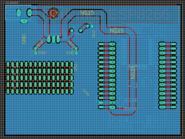
After I completed the PCB design, then I sent my PCB board Gerber files to the PCBWay Company for making High-Quality PCB’s. After generating the Gerber files, I double checked all the connections using the PCBWay online Gerber Viewer. After I was satisfied, then I placed an online order on the PCBWay official website.
About the Sponsor, PCBWay:

High quality & Only 24 Hours Build time
This PCB is sponsored and manufactured by the PCBWay Company, which is one of the most experienced PCB and PCB assembly manufacturer. They create high-quality PCBs at reasonable prices, Only 5 dollars for 10 PCBs and 30 dollars in total for 20 PCBs assembly; besides this the new members also get a 5 Dollars bonus. As you can see the quality is really great, the silkscreen is quite clear and the black solder mask looks amazing. I am 100% satisfied with their work. What are you waiting for? Go and get your first order for free.
Download link of the Nodemcu library for Cadsoft eagle:

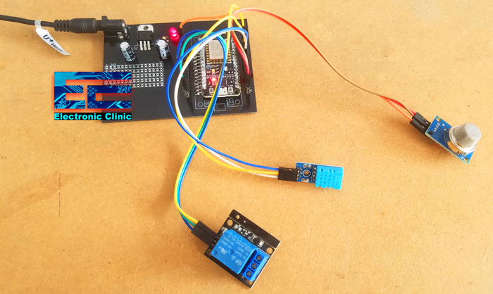
I completed the soldering and connected the DHT11, Smoke Sensor, and relay module with the Nodemcu ESP8266 module as per the circuit diagram already explained.
Blynk Application for monitoring:
I always first start with the Blynk application designing, this way I know which digital and virtual pins I have to use in the programming. Moreover this also helps me in checking my code, as I keep testing my project. Make sure you have downloaded and installed the Blynk application.
- First of all open the blynk application.
- Click on the new project and enter the project name as “Nodemcu DHT11”. If you want you can select any other name. Later you can also modify the name.
- Click on the choose device and select Nodemcu.
- Make sure the connection type is set to WIFI.
- Finally, click on the create button, an authentication token will be sent on your email id, which later will be used in the Nodemcu programming.
- Click anywhere on the screen and search for the Value Display Widget and add it to the screen. Add three Value Display Widgets. We will use these for displaying the Smoke, Humidity, and temperature values.
- Again click on the screen and this time search for the button and add it.
- Again click on the screen and this time search for the notification widget and add it.
- After adding all the required widgets, next step is to do some settings.
- Click on the first Value Display widget, set the name as smoke, select input type as the virtual pin V2, and select reading rate 1 Sec.
- Click on the 2nd Value display widget, set the name as Humidity, select the input type as the virtual pin V3, and select reading rate 1 Sec.
- Click on the 3rd Value Display Widget, set the name as Temperature, select the input type as the virtual pin V4, and select reading rate 1 Sec.
- Finally, click on the button, select D0 as the OUTPUT, Mode as Switch.
Your application should look something like this

Pay no attention to the exit1, exit2, and exit3, these are just the tabs I added. One you press on the play button you will see a red dot like thing, which means it’s not connected with the Nodemcu ESP8266.
DHT11, relay Module, and MQ2 Nodemcu ESP8266 Programming:
|
1 2 3 4 5 6 7 8 9 10 11 12 13 14 15 16 17 18 19 20 21 22 23 24 25 26 27 28 29 30 31 32 33 34 35 36 37 38 39 40 41 42 43 44 45 46 47 48 49 50 51 52 53 54 55 56 57 58 59 60 61 62 63 64 |
/* Download Libraries: https://www.electroniclinic.com/arduino-libraries-download-and-projects-they-are-used-in-project-codes/ */ #include "DHTesp.h" #include<stdlib.h> /* ESP & Blynk */ #include <ESP8266WiFi.h> #include <BlynkSimpleEsp8266.h> #include <SimpleTimer.h> #define BLYNK_PRINT Serial // Comment this out to disable prints and save space char auth[] = "6pPE2EYSdEAg0LJwvbEZBfbzW3oAJDa5"; /* WiFi credentials */ char ssid[] = "AndroidAP7DF8"; char pass[] = "electroniClinic"; SimpleTimer timer; #define DHTpin 2 // D4 on the nodemcu ESP8266 DHTesp dht; int mq135 = A0; // smoke sensor is connected with the analog pin A0 int data = 0; String mytemp; String myhum; void setup(){ Serial.begin(9600); dht.setup(DHTpin, DHTesp::DHT11); Blynk.begin(auth, ssid, pass); pinMode(D0, OUTPUT); timer.setInterval(1000L, getSendData); } void loop(){ timer.run(); // Initiates SimpleTimer Blynk.run(); } void getSendData() { delay(dht.getMinimumSamplingPeriod()); delay(1000); float humidity = dht.getHumidity(); float temperature = dht.getTemperature(); Blynk.virtualWrite(V3, humidity); Blynk.virtualWrite(V4, temperature); data = analogRead(mq135); Blynk.virtualWrite(V2, data); //virtual pin V2 if (data > 600 ) { Blynk.notify("Smoke Detected!!!"); } } |
After uploading the above code, I powered up my circuit.
I then opened my Blynk application, and I was able to receive the values.

For the testing purposes, I created some smoke to check if the value changes.

I was able to monitor the Smoke, Humidity, and temperature values. I was also able to get the notifications. If you don’t want to receive the notifications, then you can simply delete the notification widget and there is no need to delete the code on the Nodemcu side.
Related Projects:
- Firebase Android Application Designing using Android Studio, ESP32 DHT11
- Landslide detection system using wireless sensor network based on IOT
- Arduino Weather Station using dht11 and Display Data on Gauges
- ThingSpeak Nodemcu ESP8266, Send Sensors Data to ThingSpeak
- IoT Weather Station Project using Nodemcu ESP8266 and Arduino Uno
- Request Temperature Data Using GSM and Arduino
- Email in VB.net to send Arduino Sensors Data “2010 Express”
- How to use GSM and Bluetooth Together To monitor Any Sensors wirelessly using Arduino
- Sensors Data on Graphs using Arduino and vb.net
- Wireless Temperature monitoring system using Bluetooth
Discover more from Electronic Clinic
Subscribe to get the latest posts sent to your email.