Landslide detection system using wireless sensor network based on IOT
Last Updated on September 20, 2024 by Engr. Shahzada Fahad
Table of Contents
Description:
Landslide detection system- In this article you will learn how to make an advanced level early warning Landslide detection system using the Wireless Sensor Network based on the IoT “Internet of things”. This is quite an advanced level project capable of monitoring the earth vibration, Temperature, Humidity, and the Soil moisture. All these sensors are connected with different IoT Nodes which make the complete network. The number of nodes can be increased and decreased as per the requirement. All the Landslide detection nodes are monitored using a single smart phone app designed in Blynk. The IoT supported nodes are developed using the Nodemcu ESP8266 Wifi Modules. This article can be a bit longer, as I will be explaining each and every detail.
Without any further delay, let’s get started!!!
Amazon Links:
DHT11 Temperature and Humidity Module:
Arduino Nano USB C type (Recommended)
*Please Note: These are affiliate links. I may make a commission if you buy the components through these links. I would appreciate your support in this way!
Landslides are one of the major catastrophic disasters, caused by geological, hydrological effects and human activities. It is important to study the landslide induced vibrations that occur inside the earth surface, to analyze those vibrations and to correlate them with the landslide events. Though there exist systems for monitoring landslides there is an urgent need for improving the same for better monitoring of the landslide-prone areas and early warning dissemination.
Aim and objective of the Landslide Detection System:
Development of an affordable landslide detection and monitoring system using a cell phone application designed in Blynk based on the Wireless Sensor Network using IOT support devices like Nodemcu ESP8266. Though there exist systems for monitoring landslides there is an urgent need for improving the same for better monitoring of the landslide-prone areas and early warning dissemination. This landslide detection system aims for the Development of an affordable landslide monitoring system using based on the Wireless Sensor Network for efficient data collection of landslide precursor signals.
Landslide Detection System Problem Statement:
Though there exist systems for monitoring landslides there is an urgent need for improving the same for better monitoring of the landslide-prone areas and early warning dissemination, thus saving lives. In the previously designed Landslide Detection systems, no temperature, Humidity, and Soil Moisture sensors are added, they only take decisions on the basis of vibration.
In my designed project I have added the Soil moisture sensor, Temperature, and Humidity Sensor, and also the Vibration sensor. All these sensors can be monitored in real-time using the Cell phone application. From the Soil moisture values, we can decide the possible outcomes, and this way we can generate early warning alerts/messages.
Why IOT Wireless Sensor Network?
As you know IoT stands for “internet of things” using the IoT technology in the landslide detection system project, all the connected sensors can be monitored from anywhere around the world using just a cell phone. All the sensors can be monitored in real-time, automatic alerts can be generated if in case anything goes wrong.
In this project, I have used multiple monitoring nodes that make a network and acts as the wireless sensor network based on the IoT supported devices Nodemcu ESP8266 Wifi Modules.
Using IoT based Wireless Sensor Network can have so many advantages like e.g.
- Worldwide monitoring
- Real-time alerts
- Reduced wiring
- Reduce cost
- Easy installation
- Easy maintenance and so on.
Using the IoT based wireless sensor network technology for the Landslide detection system, many new nodes can be connected, without affecting the other nodes. Larger areas can be covered, and each area can be monitored in real-time. Many people use Lora and Xbee for developing the wireless sensor network which can be very expensive and needs complicated programming as you will need to send data from one node to the other node, then to the other node till the data is delivered to the final receiving module. Why do we need to do this? This technique should only be used in areas where there is no 3G or 4G technology.
Today the technology is so advanced that the internet is available everywhere, so instead of using the Lora or Xbee we can use wifi supported devices and make a complete network. All the nodes send data to the single receiving device which can be a smartphone or an IoT platform.
Working of my Landslide detection system:
In this project, I have designed three nodes.
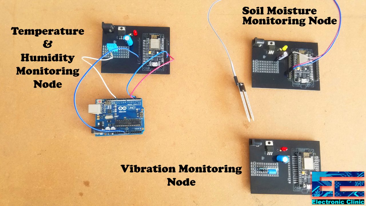
Landslide Detection System Node 1:
In node 1 a vibration Sensor “SW-420” is connected with the Nodemcu ESP8266 Wifi module. This Node is responsible for monitoring the vibrations. The vibration data is sent after every 1 second to the Blynk application. When the vibration exceeds a predefined value an alert is also generated.
Landslide Detection System Node 2:
In node 2 the DHT11 temperature and humidity sensor is connected with the Nodemcu ESP8266 Wifi module. This Node is responsible for monitoring the temperature and humidity. The temperature and humidity data is sent after every 1 second to the Blynk application where the data is displayed on the gauges. When the temperature and humidity values exceed the predefined values an alert is generated.
Landslide Detection System Node 3:
In node 3 a soil moisture sensor is connected with the Nodemcu ESP8266 Wifi module. This Node is responsible for monitoring the soil moisture. The soil moisture data is sent after every 1 second to the Blynk application. When the soil moisture exceeds a predefined value an alert is generated. The soil moisture is also monitored in real-time, this way precaution steps can be taken in advance.
I think I have shared enough data with you guys and I am sure now you have a complete understanding of what this project is all about and how this works. Now it’s time to discuss the circuit diagrams and programs.
Vibration Monitoring Node 1:
About the SW-420 Vibration Sensor:
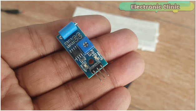
This is the SW-420 vibration sensor. As you can see it has three male headers which are clearly labeled with D0, ground and Vcc.
This Vibration sensor can be used in places where you need to monitor the vibration.
Landslide Detection System Circuit Diagram “Vibration Sensor” Node 1:

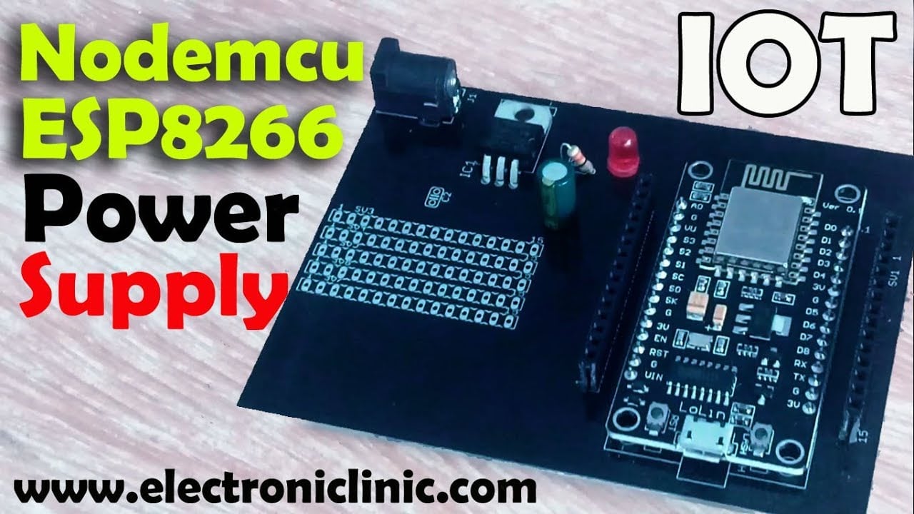
This is the complete circuit diagram of the Nodemcu esp8266 power supply. This Power Supply is based on the famous LM7805 voltage regulator. J1 is the female power jack and this is where we connect a 12v adaptor, battery, or a solar panel. Two 470uf capacitors are connected at the input and output sides of the voltage regulator. A 330-ohm resistor is connected in series with a 2.5v led. This is a current limiting resistor. The output of the voltage regulator is connected with the Vin pin of the Nodemcu esp8266 wifi module and the ground is connected with the ground. SV1 and SV2 are the female headers… D0 pin of the Vibration sensor is connected with D0 pin of the Nodemcu module, the ground pin of the vibration sensor is connected with Nodemcu ground while the VCC of the vibration sensor is connected with the 3.3v pin of the Nodemcu esp8266 wifi module.
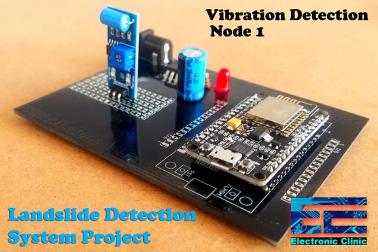
This is the final circuit, The PCB designing and online order placement is already explained in the video below. This is the basic development board which I will also use in the other 2 nodes. Thanks to the PCBWay Company for sponsoring the PCBs. The Gerber files of this PCB board can be downloaded by clicking on the link given below.
Before, you start the programming, first of all, make sure you download all the necessary libraries used in this project.
Landslide Detection System Programming “Vibration Sensor” Node 1:
|
1 2 3 4 5 6 7 8 9 10 11 12 13 14 15 16 17 18 19 20 21 22 23 24 25 26 27 28 29 30 31 32 33 34 35 36 37 38 39 40 41 42 43 44 45 46 47 48 49 50 51 52 53 54 55 56 57 58 59 60 61 62 63 64 65 66 67 68 69 70 71 72 73 74 75 76 77 |
// for vibration sensor #define BLYNK_PRINT Serial #include <ESP8266WiFi.h> #include <BlynkSimpleEsp8266.h> #include <SimpleTimer.h> // You should get Auth Token in the Blynk App. // Go to the Project Settings (nut icon). char auth[] = "2ZDyPYwAWQ3tmq7emmy_D0ypRduA_g91"; // Your WiFi credentials. // Set password to "" for open networks. char ssid[] = "AndroidAP7DF8";//ZONG MBB-E8231-6E63 char pass[] = "jamshaid"; SimpleTimer timer; // sensors int vs = D0; // vibration sensor int sdata = 0; // sensor data will be stored in this variable. String vdata = ""; // This function sends Arduino's up time every second to Virtual Pin (1). // In the app, Widget's reading frequency should be set to PUSH. This means // that you define how often to send data to Blynk App. void myTimerEvent() { // You can send any value at any time. // Please don't send more that 10 values per second. Blynk.virtualWrite(V1, millis() / 1000); } void setup() { // Debug console Serial.begin(9600); pinMode(vs ,INPUT); Blynk.begin(auth, ssid, pass); // Setup a function to be called every second timer.setInterval(10L,sensorvalue); // 1000L } void loop() { Blynk.run(); timer.run(); // Initiates BlynkTimer } void sensorvalue() { long measurement =vibration(); //delay(50); Serial.println(measurement); Blynk.virtualWrite(V3, measurement); if( measurement > 1000 ) { Blynk.notify("Vibration detected!!"); } vdata = vdata + "Vibration: " + measurement; // You can send any value at any time. // Please don't send more that 10 values per second. Blynk.virtualWrite(V4, vdata); vdata = ""; } long vibration(){ long measurement=pulseIn (vs, HIGH); //wait for the pin to get HIGH and returns measurement return measurement; } |
Temperature and Humidity Monitoring Node 2:
About the DHT11 temperature and Humidity Sensor:
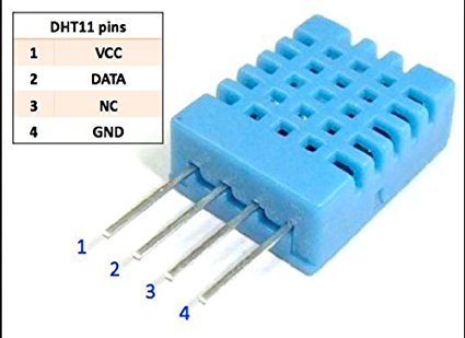
This is the DHT11 temperature and humidity sensor which is used in this project for monitoring the Humidity and temperature. DHT11 Sensor has total of 4 pins. Pin number 1 is the VCC, pin number 2 is the data, pin number 3 is not connected while pin number 4 is the Ground.
Landslide Detection System Circuit Diagram “DHT11” Node 2:

The power supply I already explained above, this power supply will be used to power up the Nodemcu ESP8266 Wifi Module.
Dht11 sensor is connected with pin12 of the Arduino. The TX and RX pin’s of the Nodemcu module are connected with pin 2 and pin 3 of the Arduino. So the Nodemcu will communicate serially with Arduino Uno through pin 2 and pin 3. Pin2 is RX and pin3 is TX, which will be defined in the programming using the software serial library.
You might be wondering why I used Arduino with the Nodemcu ESP8266 Wifi module. Well, as you know in the Nodemcu module we have only 1 analog pin A0 so the reason I added the Arduino is if in case you want to use the multiple analog sensors. Moreover, you will also learn how to use the Arduino and Nodemcu together.
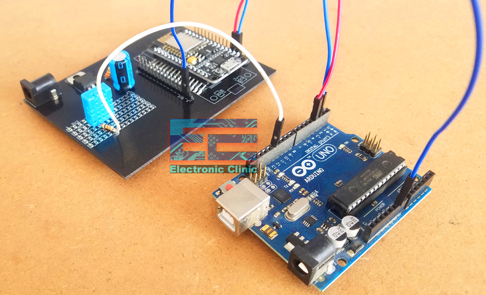
Finally, I connected everything as per the circuit diagram.
Landslide Detection System programming “Temperature and Humidity” Node 2:
As you know this node of the Landslide detection system is based on the Arduino and Nodemcu ESP8266 Wifi so for this node, we have basically two programs. One program is written for the Arduino while the other program is written for the Nodemcu ESP8266 Wifi module.
Arduino Program:
|
1 2 3 4 5 6 7 8 9 10 11 12 13 14 15 16 17 18 19 20 21 22 23 24 25 26 27 28 29 30 31 32 33 34 35 36 37 38 39 40 41 42 43 44 45 46 47 48 49 50 51 52 53 54 55 56 57 58 59 60 61 62 63 64 65 66 67 68 69 70 71 72 73 74 75 76 77 78 79 80 81 |
#include "DHT.h" #include <SoftwareSerial.h> SoftwareSerial nodemcu(2,3); #define DHTPIN 12 // what pin we're connected to //Uncomment whatever the type of sensor we are using. #define DHTTYPE DHT11 // DHT 11 //#define DHTTYPE DHT22 // DHT 22 (AM2302) //#define DHTTYPE DHT21 // DHT 21 (AM2301) // Initialize DHT sensor for normal 16mhz Arduino DHT dht(DHTPIN, DHTTYPE); boolean tflag = false; // temperature flag. // this flag will be used to stop unnecessary repetition of code. int relay = 13; int sdata1 = 0; // humidity int sdata2 = 0; // temperature String cdata; // complete data, consisting of sensors values void setup() { Serial.begin(9600); nodemcu.begin(9600); dht.begin(); pinMode(4, OUTPUT); // dht11 vcc pin is connected with pin 4 digitalWrite(4, HIGH); } void loop() { // Wait a few seconds between measurements. delay(2000); // Reading temperature or humidity takes about 250 milliseconds! // Sensor readings may also be up to 2 seconds 'old' (its a very slow sensor) int h = dht.readHumidity(); // Read temperature as Celsius int t = dht.readTemperature(); // Read temperature as Fahrenheit int f = dht.readTemperature(true); // Check if any reads failed and exit early (to try again). if (isnan(h) || isnan(t) || isnan(f)) { Serial.println("Failed to read from DHT sensor!"); return; } // Compute heat index // Must send in temp in Fahrenheit! int hi = dht.computeHeatIndex(f, h); if ( (t > 32 ) && ( tflag == false ) ) { digitalWrite(relay, HIGH); Serial.println("Fan is On"); tflag = true; } if ( (t <= 32 ) && ( tflag == true ) ) { digitalWrite(relay, LOW); Serial.println("Fan is Off"); tflag = false; } sdata1 = h; sdata2 = t; cdata = cdata + sdata1+","+sdata2; // comma will be used a delimeter Serial.println(cdata); nodemcu.println(cdata); delay(500); cdata = ""; } |
Nodemcu ESP8266 Program:
|
1 2 3 4 5 6 7 8 9 10 11 12 13 14 15 16 17 18 19 20 21 22 23 24 25 26 27 28 29 30 31 32 33 34 35 36 37 38 39 40 41 42 43 44 45 46 47 48 49 50 51 52 53 54 55 56 57 58 59 60 61 62 63 64 65 66 67 68 69 70 71 72 73 74 75 76 77 78 79 80 81 82 83 84 85 86 87 88 89 90 91 92 93 94 95 96 97 98 99 100 101 102 103 104 105 106 107 108 109 110 |
#define BLYNK_PRINT Serial #include <ESP8266WiFi.h> #include <BlynkSimpleEsp8266.h> #include <SoftwareSerial.h> #include <SimpleTimer.h> char auth[] = "2ZDyPYwAWQ3tmq7emmy_D0ypRduA_g91"; // Your WiFi credentials. // Set password to "" for open networks. char ssid[] = "AndroidAP7DF8";//ZONG MBB-E8231-6E63 char pass[] = "jamshaid"; SimpleTimer timer; String myString; // complete message from arduino, which consists of snesors data char rdata; // received characters int firstVal, secondVal,thirdVal; // sensors // This function sends Arduino's up time every second to Virtual Pin (1). // In the app, Widget's reading frequency should be set to PUSH. This means // that you define how often to send data to Blynk App. void myTimerEvent() { // You can send any value at any time. // Please don't send more that 10 values per second. Blynk.virtualWrite(V1, millis() / 1000); } void setup() { // Debug console Serial.begin(9600); Blynk.begin(auth, ssid, pass); timer.setInterval(1000L,sensorvalue1); timer.setInterval(1000L,sensorvalue2); } void loop() { if (Serial.available() == 0 ) { Blynk.run(); timer.run(); // Initiates BlynkTimer } if (Serial.available() > 0 ) { rdata = Serial.read(); myString = myString+ rdata; // Serial.print(rdata); if( rdata == '\n') { String l = getValue(myString, ',', 0); String m = getValue(myString, ',', 1); firstVal = l.toInt(); secondVal = m.toInt(); myString = ""; // end new code } } } void sensorvalue1() { int sdata = firstVal; // humidity value // You can send any value at any time. // Please don't send more that 10 values per second. Blynk.virtualWrite(V5, sdata); } void sensorvalue2() { int sdata = secondVal; // temperature value // You can send any value at any time. // Please don't send more that 10 values per second. Blynk.virtualWrite(V6, sdata); } String getValue(String data, char separator, int index) { int found = 0; int strIndex[] = { 0, -1 }; int maxIndex = data.length() - 1; for (int i = 0; i <= maxIndex && found <= index; i++) { if (data.charAt(i) == separator || i == maxIndex) { found++; strIndex[0] = strIndex[1] + 1; strIndex[1] = (i == maxIndex) ? i+1 : i; } } return found > index ? data.substring(strIndex[0], strIndex[1]) : ""; } |
Soil Moisture Monitoring Node 3:
About the FC-28 Soil Moisture Sensor:
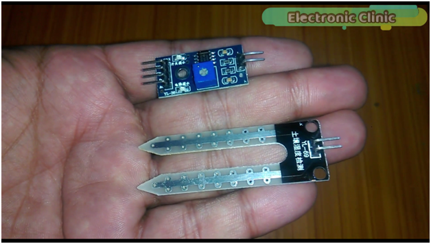
As you can see in the picture above, the soil moisture sensor consists of two components. Component number 1 is basically a two-legged lead, that goes into the soil, as you can see this component has two male headers which connect to the component number 2 which is an amplifier/ Analog to digital converter circuit.
The amplifier circuit is connected with the Arduino using the 4 male headers. These 4 male headers are labeled with Vcc, Ground, D0, and A0. D is for the digital while A is for the analog. So it means we can get values in both Digital and Analog. The digital output is in the form of 0 or 1which can be controlled using this potentiometer. This module has also two led’s, one led is the power ON led, while the other led works with the digital output pin. When the moisture is below a certain value which is set using the potentiometer then led remains off. When there is moisture, this led turns ON. While the analog output can be any number between 0 and 1024. This value will entirely depend on the water content present in the soil. So now we can say that the soil moisture sensor has two modes
- Analog Mode and
- Digital Mode.
In this project, I have used this sensor in the Analog Mode as I want to monitor the water content in real-time.
Landslide Detection System Circuit Diagram “Soil Moisture” Node 3:

This schematic is designed in cadsoft eagle 9.1.0 version. If you want to learn how to make schematics and PCB then watch my tutorial, available in the related projects section. The 5v regulated power supply remains the same.
The soil moisture Vcc pin is connected with the Nodemcu ESP8266 Wifi module 3.3v, the ground is connected with the Nodemcu ground while the A0 pin of the moisture sensor which is the analog output pin of the moisture sensor is connected with the Nodemcu analog pin A0. While the digital output pin of the moisture sensor is not connected. While the two-legged lead is connected with the SENS 1 and SENS 2 pins of the moisture sensor.

Landslide Detection System programming “Soil Moisture” Node 3:
|
1 2 3 4 5 6 7 8 9 10 11 12 13 14 15 16 17 18 19 20 21 22 23 24 25 26 27 28 29 30 31 32 33 34 35 36 37 38 39 40 41 42 43 44 45 46 47 48 49 50 51 52 53 54 55 56 57 58 59 60 61 62 63 64 65 66 67 |
// nodemcu "Soil Moisture" #define BLYNK_PRINT Serial #include <ESP8266WiFi.h> #include <BlynkSimpleEsp8266.h> #include <SimpleTimer.h> // You should get Auth Token in the Blynk App. // Go to the Project Settings (nut icon). char auth[] = "2ZDyPYwAWQ3tmq7emmy_D0ypRduA_g91"; // Your WiFi credentials. // Set password to "" for open networks. char ssid[] = "Infinix S5";//ZONG MBB-E8231-6E63 char pass[] = "12345678"; SimpleTimer timer; // sensors int vr = A0; // moisture sensor connected int sdata = 0; // sensor data will be stored in this variable. // This function sends Arduino's up time every second to Virtual Pin (1). // In the app, Widget's reading frequency should be set to PUSH. This means // that you define how often to send data to Blynk App. void myTimerEvent() { // You can send any value at any time. // Please don't send more that 10 values per second. Blynk.virtualWrite(V1, millis() / 1000); } void setup() { // Debug console Serial.begin(9600); pinMode(vr ,INPUT); Blynk.begin(auth, ssid, pass); // Setup a function to be called every second timer.setInterval(1000L,sensorvalue); } void loop() { Blynk.run(); timer.run(); // Initiates BlynkTimer } void sensorvalue() { sdata = analogRead(vr); // You can send any value at any time. // Please don't send more that 10 values per second. Blynk.virtualWrite(V2, sdata); if (sdata < 500 ) // the moisture increase as the value decreases. { Blynk.notify("Soil Moisture increased!!!"); } } |
All the three nodes “Final Look”:
Now, it’s time to make the Blynk application.
Note: this old version of the Blynk app is no more functional. For the blynk mobile App setup and Blynk.cloud dashboard setup ready my article on the New Blynk V2.0. In this article I have explained how to migrate your projects from Blynk 1.0 to the new Blynk V2.0. You can also watch the video.
- First of all open the blynk application.
- Click on the new project and enter the project name as “Land Sliding”. Or any other name which like.
- Click on the choose device and select Nodemcu.
- Make sure the connection type is set to WIFI.
- Finally, click on the create button, an authentication token will be sent on your email id, which later will be used in the Nodemcu programming. Make sure you use the same authentication code in all the nodes. As we will be using this application for monitoring all the sensors.
- Click anywhere on the screen and search for the tabs and add it. Now, click on the tab and add three tabs with names “SOIL MOISTURE”, “VIBRATION”, and “TEMP & HUMIDITY”. As you can see in the picture given below.

- While the moisture tab is selected add a gauge and select the virtual pin V2.
- Again click on the screen and this time add the notification widget.

- Now, select the VIBRATION tab. Click on the screen and add the terminal widget and select virtual pin V4.

- Now, select the TEM & HUMIDITY tab. Click on the screen and this add two gauges. Set the names as HUMIDITY and TEMP. Select the virtual pins V5 and V6.
All the virtual pins used in the Blynk app are already defined in the Nodemcu programming. If you want to use different virtual pins then you will also have to change them in the Nodemcu programming. So that’s all about the Blynk application designing.
Landslide detection System final testing:
In the end I powered up all the nodes and I successfully monitored all the nodes in real time. I was able to generate the alerts.


For the best understanding I recommend you should watch my getting started tutorials available in the related projects section. If you have any questions regarding this project let me know in a comment. Don’t forget to Subscribe to my Website and YouTube channel “Electronic Clinic”.
Related Projects:
Moisture sensor Getting started tutorial:

Temperature and Humidity Sensor weather station:

IoT Vibration Sensor:

Nodemcu power supply pcb designing in cadsoft eagle:

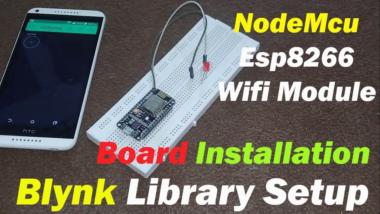
Nodemcu esp8266 wifi module board installation and blynk library:
Discover more from Electronic Clinic
Subscribe to get the latest posts sent to your email.

Hi sir, In the circuit diagram of node 1 there is a component named R2 is it a switch? because it looks like a switch and that isnt mentioned anywhere in the article. please clarify what it does sir.