Diy Internet of Things Fridge, Smart IoT Refrigerator “Nodemcu ESP8266, DS18b20, Blynk”
Last Updated on September 21, 2024 by Engr. Shahzada Fahad
Table of Contents
Description:
Diy Internet of Things Fridge or Smart IoT Refrigerator- The internet of things based Fridge or smart IoT Refrigerators are becoming very popular because with the help of a smart IoT refrigerator you can check the temperature, food items expiry date, Door opening and closing status from anywhere around the world using the Wifi technology. this project is also ideal for the temperature-controlled storage. In this article, you will learn how to convert any Fridge or Refrigerator into a smart internet of things based Fridge or Refrigerator using a Push Button or a limit Switch, Nodemcu ESP8266 Wifi Module, a variable resistor, DS18b20 one wire waterproof digital temperature sensor capable of measuring the temperature from -55C to 125 Centigrade, and a cell phone application designed in Blynk.
The Values are updated every second, the notification messages are sent to the owner each time the temperature increase above or decreases below a certain predefined value which can be adjusted using a variable resistor. Any value between -40 and +40 can be selected; this limit is specified in the programming which can be changed as per the requirement.
A pushbutton or a limit switch can be used with the Fridge or a refrigerator to check if the Fridge door is opened or closed. If the door remains open for 3 minutes a notification message is sent to the owner, the three minutes delay can be increased or decreased as per the requirement.
The notification messages are sent even if the application is running in the background. If in case due to some problem the Wifi connection is disconnected a notification message is sent to the owner or supervisor. This project can be easily modified by adding more sensors and some relays for controlling the Fridge or Refrigerator.
In this tutorial, we will cover,
- DS18B20 introduction
- Complete Circuit diagram
- Interfacing
- Blynk application designing and finally number
- Testing
Without any further delay, let’s get started!!!
Note: this old version of the Blynk app is no more functional. For the blynk mobile App setup and Blynk.cloud dashboard setup ready my article on the New Blynk V2.0. In this article I have explained how to migrate your projects from Blynk 1.0 to the new Blynk V2.0. You can also watch the video.
Amazon Product links:
DS18B20 one-wire digital temperature sensor:
*Please Note: These are affiliate links. I may make a commission if you buy the components through these links. I would appreciate your support in this way!
DS18B20 One-Wire Waterproof Temperature Sensor:

One-wire temperature sensors like the DS18B20 are devices that can measure temperature with a minimal amount of hardware and wiring. These sensors use a digital protocol to send accurate temperature readings directly to your development board without the need of an analog to digital converter or other extra hardware. You can get one-wire sensors in different form factors like waterproof and high-temperature probes–these are perfect for sensing temperature in many different projects and applications. And since these sensors use the one-wire protocol you can even have multiple of them connected to the same pin and read all their temperature values independently.
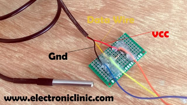
The DS18B20 Waterproof Temperature Sensor has three wires
- The red wire is the VCC wire: the operating voltage is 3 to 5 volts. In my case, I will use 3.3 volts.
- Yellow Wire is the Data wire: we usually connect a resistor between the data wire and VCC wire, I will explain this in the circuit diagram.
- The black wire is the ground wire. This wire is connected with the Nodemcu Esp8266 wifi module ground.
This temperature sensor is capable of measuring the temperature ranging from -55°C to 125°C
Internet of things Fridge Circuit Diagram:

This is the complete circuit diagram of the Smart IoT refrigerator based on the Nodemcu ESP8266 Wifi Module and DS18B20 waterproof one-wire digital temperature sensor. This Schematic is designed in cadsoft Eagle 9.1.0 version. If you want to learn how to make a schematic and PCB then watch my tutorial given below.
Let’s first of all, start with the 5v regulated Power supply which is used to power up the Nodemcu esp8266 wifi module. This Power Supply is based on the famous LM7805 voltage regulator. J1 is the female power jack and this is where we connect a 12v adaptor, battery or a solar panel. Two 470uf capacitors are connected at the input and output sides of the voltage regulator. A 330-ohm resistor is connected in series with a 2.5v led. This is a current limiting resistor. The output of the voltage regulator is connected with the Vin pin of the Nodemcu esp8266 wifi module and the ground is connected with the ground. SV1 and SV2 are the female headers.
As you can see a 4.7 Kilo ohm resistor is connected between the VCC and data wire. You can also use a 10k resistor. The VCC is connected with 3.3 volts. The ground is connected with the Nodemcu esp8266 module ground. While the Data wire is connected with digital Pin D4 of the Nodemcu ESP8266 wifi module.
The middle leg of the potentiometer or variable resistor is connected with the Analog pin A0 of the Nodemcu ESP8266 Wifi Module. While the other two legs are connected with the 3.3v and ground pins of the Nodemcu Module.
A pushbutton is connected in series with a 10k resistor. this is a pull-up resistor. A wire from the middle of the 10k resistor and pushbutton is connected with the digital pin D0 of the Nodemcu ESP8266 Wifi Module. While the switch is open 3.3v is given as the input to the D0 pin which means that the door is open. When the switch is closed means when the door is closed, the ground will be connected with the D0 pin. So, that’s all about the circuit diagram.
Interfacing of DS18b20, Potentiometer, & Pushbutton with Nodemcu:
About the PCBWay:

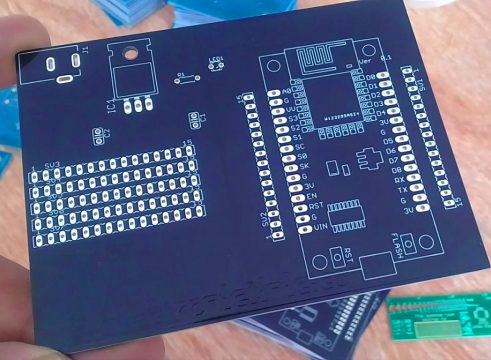
The PCB board used in this project is sponsored by the PCBway Company, which is one of the most experienced PCB and PCB assembly manufacturer. They create high-quality PCBs at reasonable prices. The Gerber files of the PCB board used in this project can be downloaded from the PCBway
High quality & Only 24 Hours Build time:
This is the Final Circuit Board manufactured by the PCBWay Company, as you can see the quality is really great, the silkscreen is quite clear and the black solder mask looks amazing.
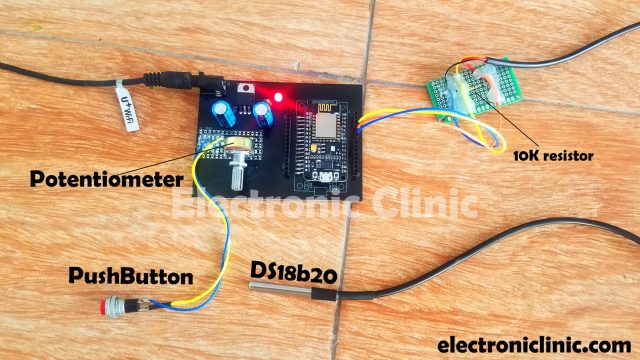
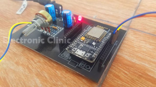
As you can see the orange wire which is the VCC wire is connected with the 3.3v, the ground wire of the DS18b20 temperature sensor is connected with the Nodemcu module ground pin, while the yellow wire which is the data wire is connected with the digital Pin D4 of the Nodemcu module.
Pushbutton is connected with the D0 pin while the Variable resistor is connected with the Analog pin A0. All the connections are exactly the same as explained in the circuit diagram. Now, let’s make the cell phone application using the Blynk.
Blynk Application designing for the Nodemcu esp8266 DS18b20:
For the Blynk application designing watch video given at the end of this article or follow the steps given below:
- First of all, open the Blynk application.
- Set the project name as IoT Refrigerator.
- Click on the choose device and select Nodemcu.
- Make sure you set the connection type to wifi. then click on the create button, an authentication token will be sent on your email id, which will be then used in the programming, simply copy and paste it in the programming.
- Click anywhere on the screen and search for the Tabs in the Widget Box and add it.
- Add three Tabs and select the Tab names as Temperature, Door Status, and Set Temp.
- While the Temperature Tab is selected click on the screen and search for the Gauge and add it. Click on the Gauge and hold it for a few seconds, change the width and height of the Gauge widget. Now click on the Gauge, enter the name as Temperature. Click on the Pin and select virtual Pin V2. Enter the minimum value -50 and the maximum value of 125. Change the font size if desired and then click on the push and select 1 second.
- Again click on the screen and this time search for the terminal and add it. Click on the terminal widget and select the virtual pin V3. Set add new line to yes and the input line to no.
- Now again click on the screen and this time search for the notification widget and add it.
- Click on the notification widget, set the Notify when hardware goes offline to ON. Finally, set the priority to High.
- While the Door Status Tab is selected, click on the screen and search for the LED widget and add it, we will need two of these. Click on the first LED set the name as Door is Opened, click on the pin and select virtual pin V4. Now, click on the 2nd LED, set the name as the Door is Closed and select the virtual pin V5.
- While the Set Temp Tab is selected, click on the screen and search for the Gauge widget and add it. Set the name as Set temperature. Select the virtual pin V6. Enter the min value as -50 and the maximum value as 50. Change the Font size and then click on the push button and select 1 second.

Application is ready, now let’s discuss the programming
Internet of Things Fridge Nodemcu Programming:
|
1 2 3 4 5 6 7 8 9 10 11 12 13 14 15 16 17 18 19 20 21 22 23 24 25 26 27 28 29 30 31 32 33 34 35 36 37 38 39 40 41 42 43 44 45 46 47 48 49 50 51 52 53 54 55 56 57 58 59 60 61 62 63 64 65 66 67 68 69 70 71 72 73 74 75 76 77 78 79 80 81 82 83 84 85 86 87 88 89 90 91 92 93 94 95 96 97 98 99 100 101 102 103 104 105 106 107 108 109 110 111 112 113 114 115 116 117 118 119 120 121 122 123 124 125 126 127 128 129 130 131 |
// temperature range of the DS18b20 // Temperature Range: -55°C to +125°C. /* ESP & Blynk */ #include <ESP8266WiFi.h> #include <BlynkSimpleEsp8266.h> #include <SimpleTimer.h> #include <OneWire.h> #include <DallasTemperature.h> #define BLYNK_PRINT Serial // Comment this out to disable prints and save space char auth[] = "1-k0JQKmFbYR5dBidgi8iRKq8XRtGMyZ"; /* WiFi credentials */ char ssid[] = "ZONG MBB-E8231-6E63"; char pass[] = "electroniclinic"; SimpleTimer timer; #define ONE_WIRE_BUS 2 // DS18B20 on arduino pin2 corresponds to D4 on physical board "D4 pin on the ndoemcu Module" OneWire oneWire(ONE_WIRE_BUS); DallasTemperature DS18B20(&oneWire); float temp; float Fahrenheit=0; int Dsensor = D0; // Refrigerator door sensor // Tracks the time since last event fired unsigned long previousMillis=0; unsigned long int previoussecs = 0; unsigned long int currentsecs = 0; unsigned long currentMillis = 0; int interval= 1; // 1 second interval int secs = 0; // current seconds int mints = 0; // current minutes int pmints = 3; // predefined minutes for the refrigerator Door int tempf = 0; // temperature flag int tvr = A0; // temperature variable resistor, variable resistor to set the temperature int Ptemp; // preset temperature. void setup() { Serial.begin(115200); Blynk.begin(auth, ssid, pass); DS18B20.begin(); pinMode(Dsensor, INPUT_PULLUP); pinMode(tvr, INPUT); timer.setInterval(1000L, getSendData); timer.setInterval(1000L, DoorSensor); } void loop() { timer.run(); // Initiates SimpleTimer Blynk.run(); } /*************************************************** * Send Sensor data to Blynk **************************************************/ void getSendData() { Ptemp = analogRead(tvr); Ptemp = map(Ptemp, 0, 1023, -40,40); DS18B20.requestTemperatures(); temp = DS18B20.getTempCByIndex(0); // Celcius Fahrenheit = DS18B20.toFahrenheit(temp); // Fahrenheit Serial.println(temp); Serial.println(Fahrenheit); Blynk.virtualWrite(V6,Ptemp); Blynk.virtualWrite(V2, temp); //virtual pin V3 if ( (temp >= Ptemp) && (tempf == 0)) { Blynk.notify("Check temperature"); tempf = 1; } if ( (temp < Ptemp) && (tempf == 1)) { Blynk.notify("looks good"); tempf = 0; } } void DoorSensor() { if(digitalRead(Dsensor) == LOW) { Blynk.virtualWrite(V4,0); Blynk.virtualWrite(V5,255); secs = 0; mints = 0; } if(digitalRead(Dsensor) == HIGH) { Blynk.virtualWrite(V4,255); Blynk.virtualWrite(V5,0); currentMillis = millis(); currentsecs = currentMillis / 1000; if ((unsigned long)(currentsecs - previoussecs) >= interval) { secs = secs + 1; if (secs >59 ) { secs = 0; mints = mints + 1; if(mints >= pmints ) { secs = 0; mints = 0; Blynk.notify("Door is opened for the last 3 mints"); } } previoussecs = currentsecs; } } Blynk.virtualWrite(V3, "Seconds"); Blynk.virtualWrite(V3, secs); Blynk.virtualWrite(V3, "Mints"); Blynk.virtualWrite(V3, mints); Blynk.virtualWrite(V3,"*********"); } |
Program explanation:
|
1 2 3 4 5 6 7 8 9 |
#include <ESP8266WiFi.h> #include <BlynkSimpleEsp8266.h> #include <SimpleTimer.h> #include <OneWire.h> #include <DallasTemperature.h> |
Before you start the programming first of all, make sure that you download all the necessary libraries by clicking on the download link given below.
Make sure you update the Nodemcu board.
|
1 |
char auth[] = "1-k0JQKmFbYR5dBidgi8iRKq8XRtGMyZ"; |
This is the Authentication token which was sent via Email. I simply copied and paste it over
here.
|
1 2 3 |
char ssid[] = "ZONG MBB-E8231-6E63"; char pass[] = "electroniclinic"; |
This is the name of the wifi router and password.
|
1 2 3 4 5 6 7 |
SimpleTimer timer; #define ONE_WIRE_BUS 2 // DS18B20 on Arduino pin2 corresponds to D4 on physical board "D4 pin on the Ndoemcu Module" OneWire oneWire(ONE_WIRE_BUS); DallasTemperature DS18B20(&oneWire); |
The data wire of the ds18b20 is connected with the digital Pin D4 of the Nodemcu Module.
|
1 2 3 |
float temp; float Fahrenheit=0; |
Then I defined two variables of the type float for storing the temperature.
|
1 |
int Dsensor = D0; // Refrigerator door sensor |
A push-button is connected with the digital pin D0 of the Nodemcu esp8266 wifi module. This button is used to check whether the Refrigerator / Fridge door is opened or closed. You can replace this button with any other digital sensor as per your requirement.
|
1 2 3 4 5 6 7 8 9 10 11 12 13 14 15 |
// Tracks the time since the last event fired unsigned long previousMillis=0; unsigned long int previoussecs = 0; unsigned long int currentsecs = 0; unsigned long currentMillis = 0; int interval= 1; // 1 second interval int secs = 0; // current seconds int mints = 0; // current minutes |
These variables are used for calculating the seconds and minutes.
|
1 |
int pmints = 3; // predefined minutes for the refrigerator Door |
This is the predefined value for the refrigerator door if the refrigerator door is kept open for 3 minutes a notification message will be sent to the Owner or Supervisor.
|
1 |
int tempf = 0; // temperature flag |
Tempf is a variable of the type integer which is used as the flag. This is used to stop the unnecessary repetition.
|
1 |
int tvr = A0; // temperature variable resistor, variable resistor to set the temperature |
A variable resistor is connected with the Analog pin A0 of the Nodemcu Module. This is used to set the temperature.
|
1 |
int Ptemp; // preset temperature. |
While the Ptemp variable is used to store the predefined temperature value which is set using the variable resistor.
|
1 2 3 4 5 6 7 8 9 10 11 12 13 14 15 16 17 18 19 |
void setup() { Serial.begin(115200); Blynk.begin(auth, ssid, pass); DS18B20.begin(); pinMode(Dsensor, INPUT_PULLUP); pinMode(tvr, INPUT); timer.setInterval(1000L, getSendData); timer.setInterval(1000L, DoorSensor); } |
In the void setup() function the door sensor and the variable resistor are set as the input.
getSendData() and DoorSensor() functions are the user defined functions which are executed after every 1 second.
Then starts the void loop function, which consists of only two functions timer.run() and blynk.run().
getSendData() is a user-defined function, it has no return type and does not take any arguments as the input. The purpose of this function is to read the variable resistor and temperature sensor. First, we read the variable resistor, set the range from -40 to +40. You can change this limit. Then we read the temperature and send the preset temperature value and the actual temperature sensor value to the Blynk application using the virtual pins V6 and V2, where these values are displayed on the Gauges.
Next, two conditions are used to check whether the temperature value is greater than or less than the predefined value…
The DoorSensor() is a user-defined function, it has no return type and does not take any argument as the input. This function is used to check if the Refrigerator/fridge door is opened or closed.
|
1 2 3 4 5 6 7 8 9 10 11 12 13 14 15 16 |
if(digitalRead(Dsensor) == LOW) { Blynk.virtualWrite(V4,0); Blynk.virtualWrite(V5,255); secs = 0; mints = 0; } |
This condition means if the door is closed, then turn off the door open led and turn ON the door closed led, and make the seconds and minutes equal to 0.
|
1 2 3 4 5 6 7 8 9 10 11 12 13 14 15 16 17 18 19 20 21 22 23 24 25 26 27 28 29 30 31 32 33 34 35 36 37 38 39 40 41 42 43 |
if(digitalRead(Dsensor) == HIGH) { Blynk.virtualWrite(V4,255); Blynk.virtualWrite(V5,0); currentMillis = millis(); currentsecs = currentMillis / 1000; if ((unsigned long)(currentsecs - previoussecs) >= interval) { secs = secs + 1; if (secs >59 ) { secs = 0; mints = mints + 1; if(mints >= pmints ) { secs = 0; mints = 0; Blynk.notify("Door is opened for the last 3 mints"); } } previoussecs = currentsecs; } } |
While this condition means if the door is opened, then turn ON the door opened LED and turn OFF the door closed LED and start counting the seconds and minutes. So, if the mints are greater than the pmints which are equal to 3 minutes, then reset the seconds and mints and send a notification message to the Owner or Supervisor.
|
1 2 3 4 5 6 7 8 9 |
Blynk.virtualWrite(V3, "Seconds"); Blynk.virtualWrite(V3, secs); Blynk.virtualWrite(V3, "Mints"); Blynk.virtualWrite(V3, mints); Blynk.virtualWrite(V3,"*********"); |
While these instructions are used to send the current seconds and minutes to the Blynk application terminal widget.
The internet of things fridge or Smart IoT Refrigerator was a great success. For the practical demonstration watch video given below. Don’t forget to Subscriber to my Website and YouTube channel.
Watch Video Tutorial:

Discover more from Electronic Clinic
Subscribe to get the latest posts sent to your email.


Hi Shahzada
I like your project Iot fridge however I have a problem when trying to verify the code:
at line 26 it states :int Dsensor = D0; // Refrigerator door sensor
when trying to verify I get the error: ‘D0’ was not declared in this scope
any help appreciated