SSD1306 Oled with ESP32 and ESP8266 WiFi Module, SSD1306 Oled ESP32, SSD1306 Oled ESP8266
Table of Contents
SSD1306 Oled with ESP32 and ESP8266, Description:
SSD1306 Oled Display Module Interfacing with ESP32 and ESP8266– In this tutorial, you will learn how to use the SSD1306 Oled Display with ESP32 WiFi + Bluetooth Module and Nodemcu ESP8266 WiFi Module.
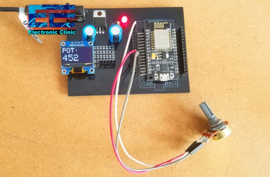
A Potentiometer is connected with the Analog pin A0 of the Nodemcu Module, while the Oled display module is connected with the I2C pins D1 and D2. The value on the LCD is updated after every 2 seconds.
About the Sponsor PCBWay:
High quality & Only 24 Hours Build time
Download PCB Boards Gerber Files:
The Nodemcu ESP8266 and ESP32 power supply PCB boards used in this project are sponsored by the PCBWay Company. PCBWay is quite professional in the field of PCB manufacturing; you can try their services at extremely low prices, Only 5 dollars for 10 PCBs and 30 dollars in total for 20 PCBs assembly, besides this the new members also get a 5 Dollars bonus. The Gerber files of the PCB boards used in this project can be downloaded from the PCBWay official website; the Gerber files download links are given above.
I also connected the same Potentiometer with the analog pin A0 of the ESP32. The Oled display module is connected with the GPIO pins 21 and 22 which are the I2C pins.
In my previous article, I have already covered the extreme basics including
- Oled Interfacing with Arduino,
- How to fix some common issues
- How to select a proper library
- How to use the basic Oled functions
- How to print text messages and Numbers, and
- How to draw different shapes
There are two versions of the same Oled display the one is SH1106 and the other one is the SSD1306. If you look at both the modules it’s hard to tell which one is the SSD1306 and which one is the SH1106 Oled display Module. So, if you want to learn how to differentiate between the two Oled display modules, How to find the I2C address, and how to fix the most common issues then I highly recommend read my previous article.
Without any further delay, let’s get started!!!
Amazon Purchase Links:
ESP32 WiFi + Bluetooth Module(Recommended)
SSD1306 128×64 Oled i2c display Module
Other Tools and Components:
Super Starter kit for Beginners
PCB small portable drill machines
*Please Note: These are affiliate links. I may make a commission if you buy the components through these links. I would appreciate your support in this way!
SSD1306 Oled Display Module:
This is the 128×64 I2C supported SSD1306 Oled Display Module. It has a total of 4 male headers, clearly labeled as GND, VCC, SCL, and SDA. This Oled display module can be easily powered up using 3.3 to 5 volts. As the ESP32 and ESP8266 are 3.3V controller boards, so we will use 3.3 volts to power up the Oled Display module.
ESP32 I2C Pins:
If you take a look at the Pinout of the ESP32, you will find GPIO21 is the SDA and GPIO22 is the SCL. So using these two pins multiple I2C supported devices can be connected with ESP32 WiFi + Bluetooth module.
Nodemcu ESP8266 I2C Pins:
Now, if you take a look at the Pinout of the Nodemcu ESP8266, D1 is the SCL and D2 is the SDA. D1 and D2 can be used to connect multiple I2C supported devices.
SSD1306 Oled Interfacing with ESP32, Circuit Diagram:
The 5v regulated power supply based on the 7805 voltage regulator is used to power up the ESP32. A wire from the output of the voltage regulator is connected with the 5V pin of the ESP32. Make sure the GND of the 5V power supply is connected with the GND of the ESP32.
A potentiometer is connected with the Analog Pin A0 which is the GPIO36. The other two legs of the Potentiometer are connected with 3.3V and GND.
The Oled display Module SCL and SDA pins are connected with the GPIO Pins 22 and 21. While the VCC and ground pins of the 128×64 Oled display Module are connected with the 3.3V and GND.
SSD1306 Oled Interfacing with ESP8266 Nodemcu, Circuit Diagram:
For the Nodemcu ESP8266, I am using the same 5V regulated power supply. The output of the voltage regulator is connected with the VIN pin of the Nodemcu ESP8266 WiFi module. Don’t forget to connect the GND of the power supply with the GND pin of the Nodemcu ESP8266.
The same value potentiometer is connected with the Analog pin A0 of the Nodemcu ESP8266. You know in Nodemcu ESP8266 we have only one Analog pin, while in ESP32 we have got multiple analog pins. So, if you need more analog pins you can switch to ESP32. Anyhow, the SCL and SDA pins of the SSD1306 Oled display module are connected with the D1 and D2 pins which are the I2C pins; while the VCC and GND pins of the Oled display module are connected with the 3.3v and GND pins of the Nodemcu ESP8266 Wifi Module.
SSD1306 Oled with ESP32 and ESP8266 Programming:
|
1 2 3 4 5 6 7 8 9 10 11 12 13 14 15 16 17 18 19 20 21 22 23 24 25 26 27 28 29 30 31 32 33 34 35 36 37 38 39 40 41 42 43 44 45 46 47 48 49 50 51 52 53 54 55 56 57 58 59 60 61 62 63 64 65 66 67 68 69 70 71 72 73 74 75 76 77 |
/* Download Libraries: https://www.electroniclinic.com/arduino-libraries-download-and-projects-they-are-used-in-project-codes/ */ #include <Wire.h> #include <Adafruit_GFX.h> #include <Adafruit_SSD1306.h> #include <SimpleTimer.h> #define REPORTING_PERIOD_MS 2000 SimpleTimer timer; uint32_t tsLastReport = 0; // for the OLED display #define SCREEN_WIDTH 128 // OLED display width, in pixels #define SCREEN_HEIGHT 64 // OLED display height, in pixels // Declaration for an SSD1306 display connected to I2C (SDA, SCL pins) #define OLED_RESET -1 // Reset pin # (or -1 if sharing Arduino reset pin) Adafruit_SSD1306 display(SCREEN_WIDTH, SCREEN_HEIGHT, &Wire, OLED_RESET); int Potentiometer = A0; int PotVal = 0; void setup() { Serial.begin(115200); pinMode(Potentiometer,INPUT); display.begin(SSD1306_SWITCHCAPVCC, 0x3C); timer.setInterval(2000L, getSendData); display.clearDisplay(); display.setTextColor(WHITE); } void loop() { timer.run(); // Initiates SimpleTimer if (millis() - tsLastReport > REPORTING_PERIOD_MS) { PotVal = analogRead(Potentiometer); tsLastReport = millis(); } } void getSendData() { // Oled display display.clearDisplay(); // display R G B Values display.setTextSize(3); display.setCursor(0,0); // column row display.print("POT:"); display.setTextSize(4); display.setCursor(0,30); display.print(PotVal); display.display(); } |
This code works with the ESP32 and also with the ESP8266 without even changing a single instruction. Only the connections on the Hardware side are different. As usual, before you start the programming, first of all, make sure you download all the necessary libraries.
The purpose of this program is to read the Potentiometer connected with the Analog pin A0, and then display the value on the SSD1306 Oled display module using ESP32 and ESP8266. The value on the Oled display is updated after every 2 seconds.
