Centrifugal Pump Working with impeller types explained
Centrifugal Pump Working:
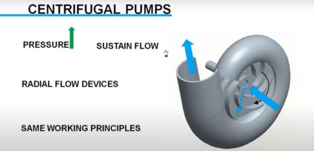
Centrifugal pumps are most commonly used turbo machinery devices which are used to raise pressure or induce flow in the control volume. They are radial flow devices, various kinds of centrifugal pumps are available in market with different construction details but working principle behind all of them remains same. In this article, we will analyze working principle of a centrifugal pump with single suction semi-open impeller. One of such pump is shown in Figure with one part of its casing removed for ease of understanding.
Watch Video Tutorial, by Learn Engineering:
Working of centrifugal pump is simple as the impeller rotates, it sucks fluid from outside through I of impeller the fluid is pushed radially along the impeller to the casing. Casing collects the fluid and it is pumped out through discharged nozzle. Now, we will discuss in detail the main components of a centrifugal pump.
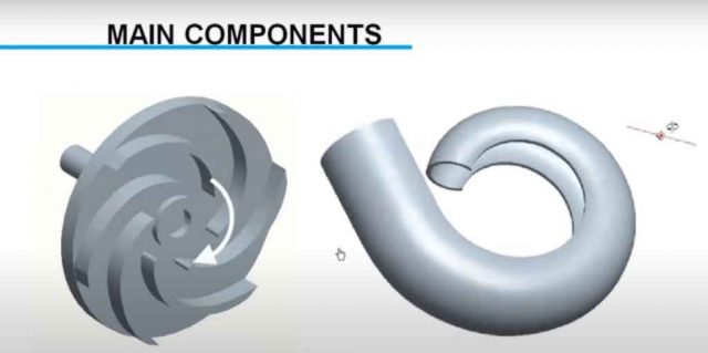
First impeller, Impeller is the device which rotates and transfer energy to fluid it has got collection of veins fitted to a hub plate. Next component is casing which collects fluid from impeller in an efficient way, the casing has got a special shape with area of cross-section increases from Inlet to outlet. As the impeller rejects fluid throughout casing along length of casing mass flow rate increases. Almost same velocity can be maintained if the area of casing is increased. Thus volute casing helps in converting dynamic part of fluid energy to static part. It will be interesting to know about instruction details of volute casing.
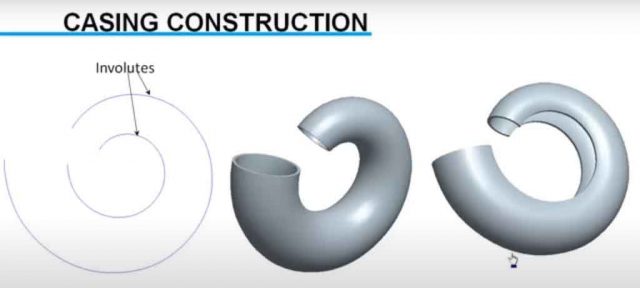
Casing is made on Tuvalu curves which are at offset. A three-dimensional volute is made from this curves. a portion is removed from volute shape in order to accommodate the impeller in it. On the exit portion of the casing a discharge nozzle is fitted. Usually the discharge nozzle is diverging in shape.
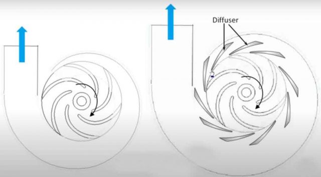
For centrifugal pumps of small capacity as we discussed impeller and casing or its main components, but for larger centrifugal pumps there will be additional diffuser blades also present in order to reduce velocity further or they aid in dynamic to static energy conversion.
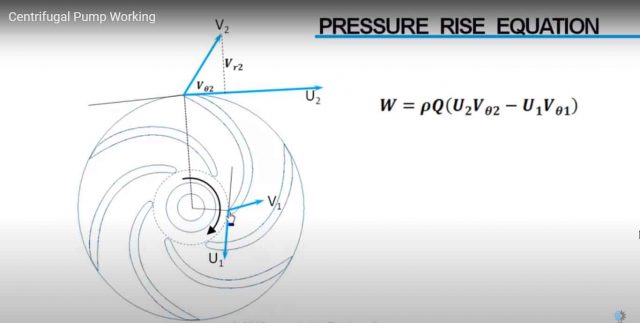
Now we will see how to predict pressure rise, blade velocities at Inlet and outlet are shown here.
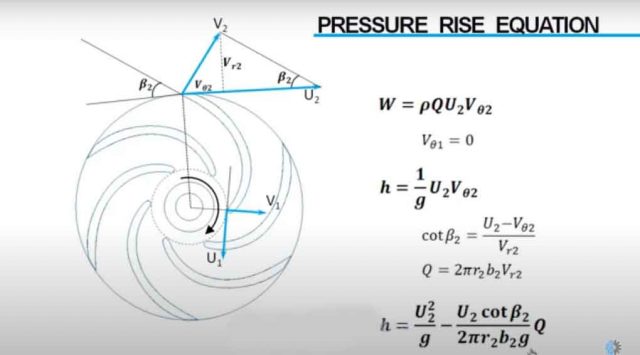
Fluid velocities at Inlet and outlet are also marked. Here you can see fluid velocity increases from Inlet to outlet due to energy addition to fluid. The work required for changing Inlet velocity condition to outlet is given by this equation W = pQ(U2Vθ2 – U1Vθ1). Here Q is the flow rate and V theta represents tangential velocity component of flow for a centrifugal pump. Inlet velocity will be parallel to radius so tangential component at Inlet is zero.
From here we can find, what’s the head rise in meters of fluid. Outlet blade angle beta can be derived in terms of velocities also flow rate through impeller is given as flow area times radial velocity so head rise in a centrifugal pump can be derived in terms of flow rate.
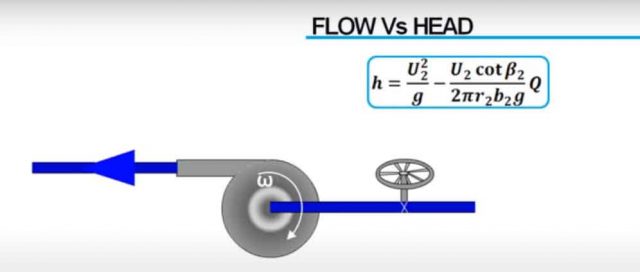
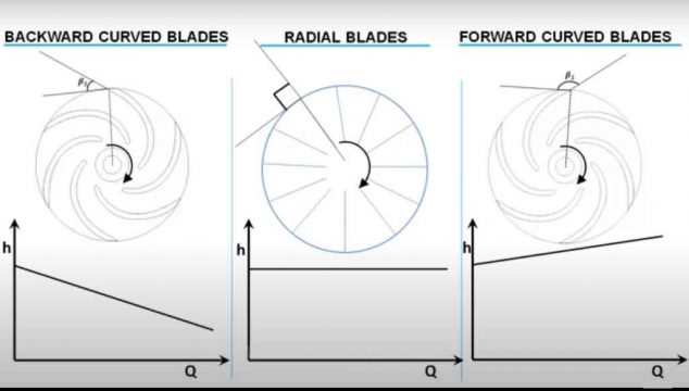
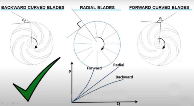
Using this we can predict what’s the head rise as we change the flow rate for a particular pump geometry and a particular impeller angular velocity. Most important parameter in this equation is blade outlet angle beta. there can be three different pop characteristics depending upon value of this angle.
First case,
If beta is less than 90 degree, since this term is positive in this case pressure head decreases with increase in flow.
These kinds of impellers are called backward curved. If beta is 90 degree with flow rate there is no change in pressure rise because this term is zero here. They are called radial type. If beta is more than 90 degree pressure increases with increase in flow rate. Such blades are called forward curved blades. The big question out of these which one is the most suited for industrial use, to get answer for this question let’s see how power consumption varies with discharge for each of these cases.
For backward curved blades as pressure head decreases with discharge power consumption stabilizes with flow. In radial blades since pressure does not have any connection with flow rate power consumption increases linearly. In forward curved blades sense pressure head increases with flow power consumption increases exponentially making the operation unstable this will lead to burnout of motor. so backward curved blades which has got self-stabilizing characteristics in power consumption is the most preferred one in industry.
