Electrical Instruments And Circuits Installation For: Fire Alarm and Smoke Alarm Security System
Last Updated on October 18, 2023 by Engr. Shahzada Fahad
Table of Contents
Signal Communication Circuits
Electrical Instruments And Circuits Installation For: Fire Alarm and Smoke Alarm Security System- In industries and commercial buildings, such electrical instruments and circuits are installed keeping in view security measures, which do not deal directly with the extension of industrial production or expanding the business activities of the commercial buildings, rather these circuits and equipment continuously supervise the system of which they are part and immediately pass on a danger signal to the control system through its circuits in a situation of any abnormal happening. However, it must be remembered that signals are also transmitted and fetched in situations of normal circumstances as well. Thus, transmission or receipt of signals during normal or abnormal conditions is called signal communication. Whereas the circuits being used for this purpose are known as signal communication circuits. In other words, circuits used for information, communication, or transmission, through which communications signals can be transmitted or received, are called signal communication circuits. Remember that communication of signals in the signal communication circuits can be done in the following forms;
(1). Audio signal communication e.g., call bells installed in houses or offices, industrial horns or hooters, fire alarms, alarm clocks, telephone bells, etc.
(2). Video signal communication e.g., multi-colored signals in a control room which indicate normal or abnormal levels of temperature, moisture, pressure, coolness, etc. Besides this, traffic control signals which consist of red, yellow, and green lights, which control the traffic system, are also an example of video signal communication.
(3). The protection signal communication is that type of communication in which signals are transmitted or received as a result of an abnormal happening as protective measures e.g., motor switching off signal as a result of water tank filling, the overload relay trip signal upon excessive heating of a motor and signal or sound upon stealing of any item, etc.
(4). Voice communication or telephonic communication, telephone, intercom, wireless and mobile are typical examples of wireless communication in present times.
(5). Control signal communication, controlling the temperature levels of fridges and air conditioners in industries and homes, setting up various operations taking place in industries at various levels, and running of motors at different speeds; all these tasks are performed through control signal communication.
Fire Alarm
In medium and large size commercial buildings and factories, such distinct circuits are installed to invite the attention of employees and ordinary people during a fire incidence, which runs a peculiar type of alarm in the event of a fire break out. These circuits are called fire alarm circuits whereas the honking alarm in the event of a fire, is known as a fire alarm. In other words, alarms installed at a specified place, which turn ON only in the situation of a fire incidence to intimate or alarm people about the fire danger or which point out the presence of fire, are called fire alarms.
According to section 36 (7) of the 1937 factories Act, it is necessary to install protective circuits and equipment like a fire alarm in all those commercial buildings, industrial organizations, and factories where 20 or more people work. The objective of a fire alarm system is to immediately alert about the danger of a fire breaking out, so that loss of human lives can be avoided. Apart from this, its objective is also to gain the immediate attention of the fire-fighting staff. As a fire alarm informs about an unforeseen situation, therefore it must be such that its sound must spread across the entire commercial building or factory, or at least to the place, where concerned fire extinguisher staff is stationed (i.e., a fire alarm system should be such that its sound can easily be heard by any person working in the factory or commercial building). To convey the alarm sound to every person, alarm points used to turn ON alarms must be easily accessible at prominent spots within the factory or a commercial building, so that in case of emergency, an alarm can be manually turned ON immediately from the nearest located alarm point. A fire alarm must comprise one or more than one siren, horn or bells, or similar other warning devices and its points should be manually operated or driven. Every point of a fire alarm generally consists of a red color knob or key, which can be pressed or turned manually to turn ON an alarm. Such automatic fire alarms are also available, which start running after the eruption of smoke within a building or when its temperature increases. In fact, some points of such alarms are associated with smoke detectors and heat-sensitive relays, which sense heat or smoke within a building to turn it ON. As such, fire alarm tends to run as a result of the presence of smoke in a building, or an increase in its temperature.
The manually operated fire alarm circuits are designed through the following two methods;
(1). Open circuit fire alarm
(2). Closed-circuit fire alarm
Open Circuit Fire Alarm
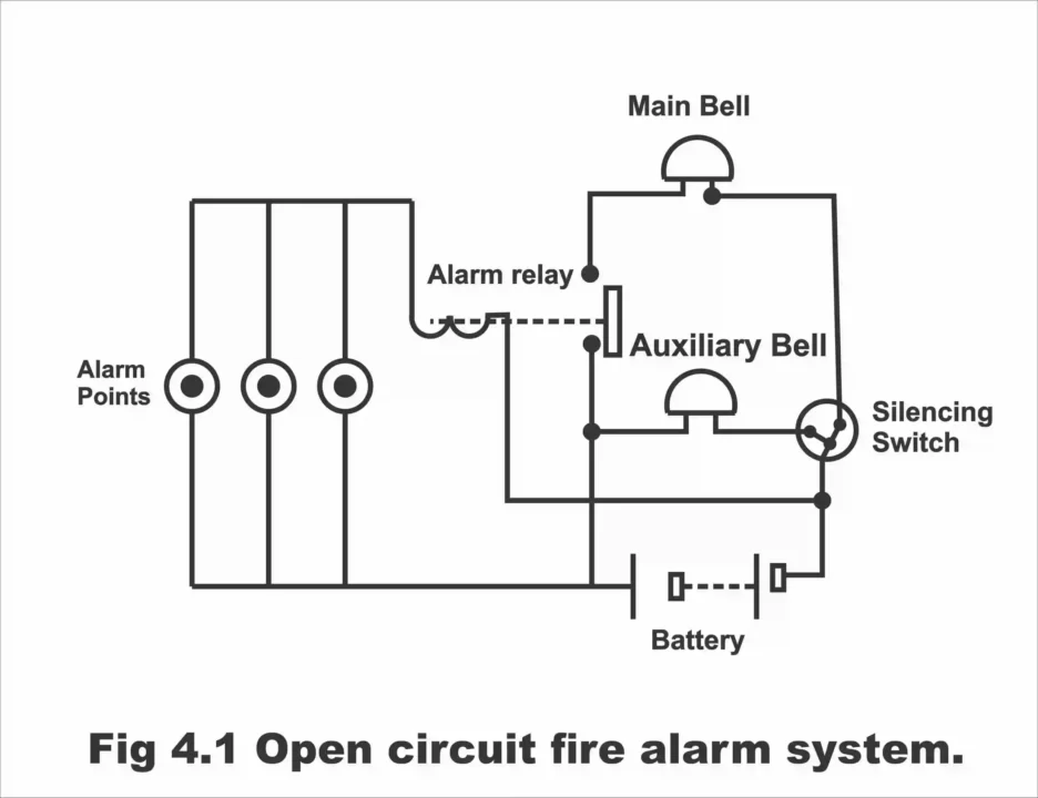
A fire alarm circuit consisting of alarm points set in parallel, wherein alarm relay are de-energized and alarm circuit is open, is called an open circuit fire alarm. These types of fire alarms are mostly used in small buildings or installations. In figure 4.1, an open circuit fire alarm system has been illustrated.
Figure 4.1 – open circuit fire alarm system
Construction
An open circuit fire alarm consists of the main bell, alarm relay with normally open contacts, an auxiliary bell, a supply source, a silencing switch the task of which is to silence the electric bell, and several red color alarm points, or bell pushers, the number of which depends on the number of fire alarm control spots apart from installation needs and the size of a commercial or industrial building. Remember that all alarm points along with an open circuit fire alarm, are fitted parallel to each other in suitable places at a height of 1.5m. In the figure, three-alarm points set in parallel have been depicted. These points are normally fixed at a distance of about 30 meters both within and outside the building.
Working Method
When any of the alarm points or alarm buttons is pushed manually, in such a situation alarm relay coil energizes and closes its normally opened contacts. As a consequence of the closing of the open contacts of the alarm relay or as a result of their joining together, the alarm circuit gets complete and closes (i.e., contacts of the sound circuit close) and the main bell starts to ring. As long as the alarm circuit remains complete, this bell rings continuously. The main bell can sometimes be silenced through a cut-off switch or a silencing switch, which is a two-way switch. However, an auxiliary bell starts to ring by doing so (because owing to the operation of the silencing switch, the circuit of the main bell remains opened whereas the circuit of the auxiliary bell closes, as has been illustrated in the figure. Thus, the main bell stops ringing while the auxiliary bell starts ringing). The auxiliary or small bell continues ringing until the pushed button is reverted to its original condition (i.e., until it is reset). Therefore, when the pushed alarm point is closed by bringing it back to its original state (i.e., by resetting it) the auxiliary or small bell silences, and the main bell fully cuts-off from the supply. However, if a small bell is turned OFF before resetting the alarm point, the main alarm or main bell starts ringing once again. Thus, an alarm circuit can be turned OFF only through the resetting of an alarm point. As a result of resetting the alarm point, the alarm relay coil de-energizes, due to which, its closed contacts re-open again and the supply to the main bell disconnects (i.e., the circuit of the main bell opens) and the entire alarm circuit turns OFF.
Closed Circuit Fire Alarm
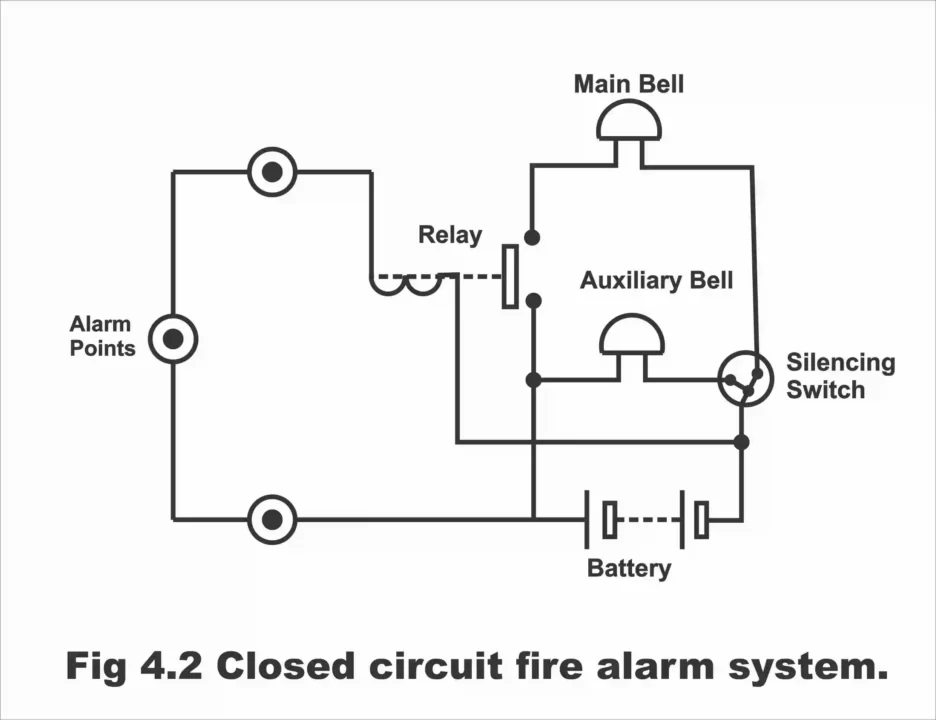
A fire alarm circuit consisting of alarm points fitted on a series, in which the installed fire alarm relay energizes in normal conditions and the alarm circuit is normally closed, is called a closed-circuit fire alarm. As such, the alarm relay remains energized in normal conditions and keeps the sounder’s circuit contacts open. In figure 4.2, a closed-circuit fire alarm system consisting of three-alarm points has been illustrated.
Figure 4.2 – close circuit fire alarm system
Construction
A closed-circuit fire alarm consists of the main bell, a normally closed contacts alarm relay, an auxiliary or small bell, a silencing switch for silencing the main bell, and several red-colored alarm points fitted together in a series the number of which depends on the number of places for fire alarm control, and a supply source. Remember that this circuit normally remains closed (as can be deduced from its name). The coil of the alarm relay remains energized during normal circumstances, whereas its contacts remain open.
Working Method
During abnormal situations or emergencies, whenever any alarm point or bell push is operated or turned ON or pushed manually, then as a result of the breaking of the alarm circuit, the coil of the already energized relay de-energizes, and relay’s normally open contacts close immediately (i.e., sounder contacts connect), due to which the main alarm starts ringing, which can be turned OFF through bringing back the pushed alarm point to its original condition (i.e., through resetting). The operation of a silencing switch in a closed-circuit fire alarm is also exactly similar to the function of the switch installed in an open circuit fire alarm.
Fire Alarm in Larger Installations
In a larger installation, where it is difficult to track or see the source of alarm or accident place, installation of some type of an indicating system is necessary for such places. The source of an alarm can easily be tracked by doing so (that’s fire location or accident spot can easily be found out). Moreover, a proposed action can also be decided quickly in the case of a fire incidence. In figure 4.3, the fire alarm circuit being used in a larger installation has been illustrated. In this figure, indicator lamps installed on an indicator board, have also been displayed to track down the accident spot. All the alarm points in this circuit have been fitted on a series and relay coils always tend to remain energized.
The operation of this circuit is as follows;
When any one of the three-alarm points fitted above the top line is turned ON, then already energized relay coil No. 1, de-energizes, and its normally open contacts, close. As such, the sounder circuit completes via indicator lamp No. 1. As a result, indicator lamp No. 1 illuminates or flashes and all the alarm bells start ringing simultaneously. Now, if no further action is taken, these bells will continue ringing non-stop until the turned-on alarm point is reset. If the main alarm bells are desired to be closed, then the cut-off switch installed on lamp number 1 is operated. However, by doing so, auxiliary or small bells start ringing and indicator lamp number 1 will continue to be irradiated. It must be kept in mind that despite operating the cut-off switch installed on lamp number 1, turning ON any alarm points associated with relay number 2 and relay number 3, the operation of re-ringing of alarms cannot be stopped (i.e., despite the operation of the cut-off switch installed on lamp number 1, if a person turns ON any one of the alarm points fitted on a series of relay number 2 and relay number 3, then fire alarm starts ringing once again). To close the auxiliary or small sounder, the original alarm point which has been turned ON is reset. By doing so, the cut-off switch reverts automatically to its original position.
Figure 4.3- fire alarm circuit with indicator lamps used in large installations
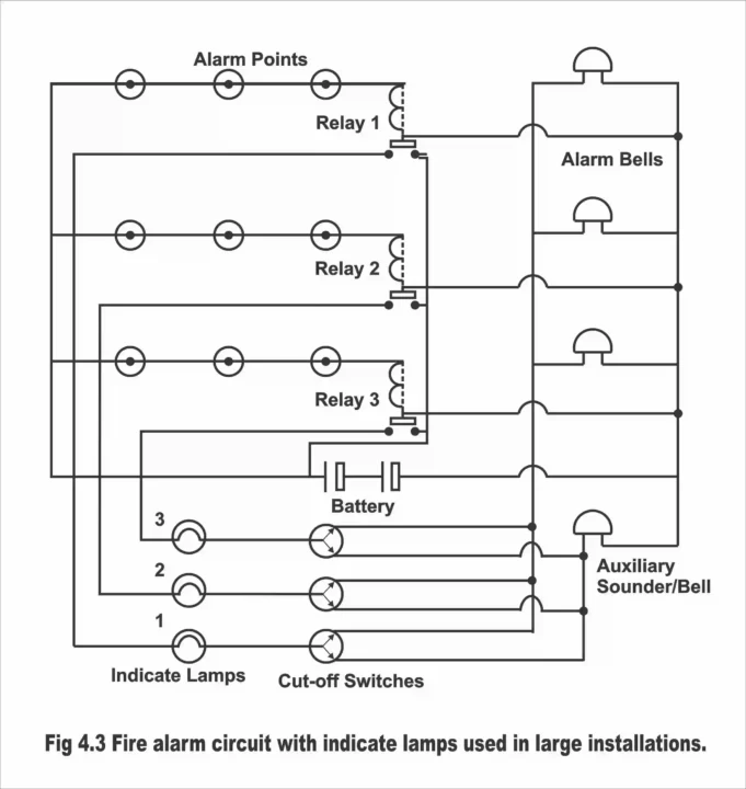
The required power for this type of alarm system is obtained from a continuous trickle-charged secondary battery through a joint of batteries, wherein one of the batteries is on load, whereas the other one keeps charging or it is in a standby state. The manually operated alarm points in a fire-protected building should be set on such spots, where access of people could be easy. No one must travel for more than 30 meters (100 feet) to ring the bell (i.e., an alarm point must necessarily exist after every 30 meters). Alarm points should be available on exit points of the building, particularly stairs and outward alleys or paths leading towards the road. So that during coming out of the building, anybody can run the alarm without wasting any sort of time. Alarm points should be painted in red, and clear instructions about their operation or turning ON should be available on it. All alarm points must be lighted and they should also be properly numbered so that they could be identified easily. Moreover, every alarm point should be approx. 1.5 meters or 4 feet and 6 inches above the ground or floor.
Sprinkler
Water sprinkles set at different angles around gigantic electric equipment, which automatically sprinkles water on this electric equipment as a result of their warming up intensively or emission of smoke as a result of setting on fire, are known as sprinklers. In other words, a piece of protective equipment, which automatically starts sprinkling water on an electric installation after its temperature exceeds a certain limit or sensing smoke, is called a sprinkler.
Sprinklers are normally built around all the electrical installations mounted on a power station especially huge turbines, generators, front parts of boilers, and transformers which are at risk of getting heated excessively, which turn ON automatically as a result of an increase in the temperature beyond a certain limit or appearance of smoke, and which cools down huge transformers through the sparkling of water in pressure from all sides or help in putting out a fire on them. The heat detectors or smoke detectors are installed along with all such electrical installations, which emit heat extensively. By means of sensing immense heat and smoke, they open water valves through an electrical operation. Thus, water sprinkles on a desired spot or installation via a sprinkler, as a result of which it cools down. The use of sprinklers is normally done in very large power stations and substations. Remember that a sensor is also installed with a piece of equipment on which a sprinkle has been mounted, which tends to be in the form of a heat detector or smoke detector.
Operation
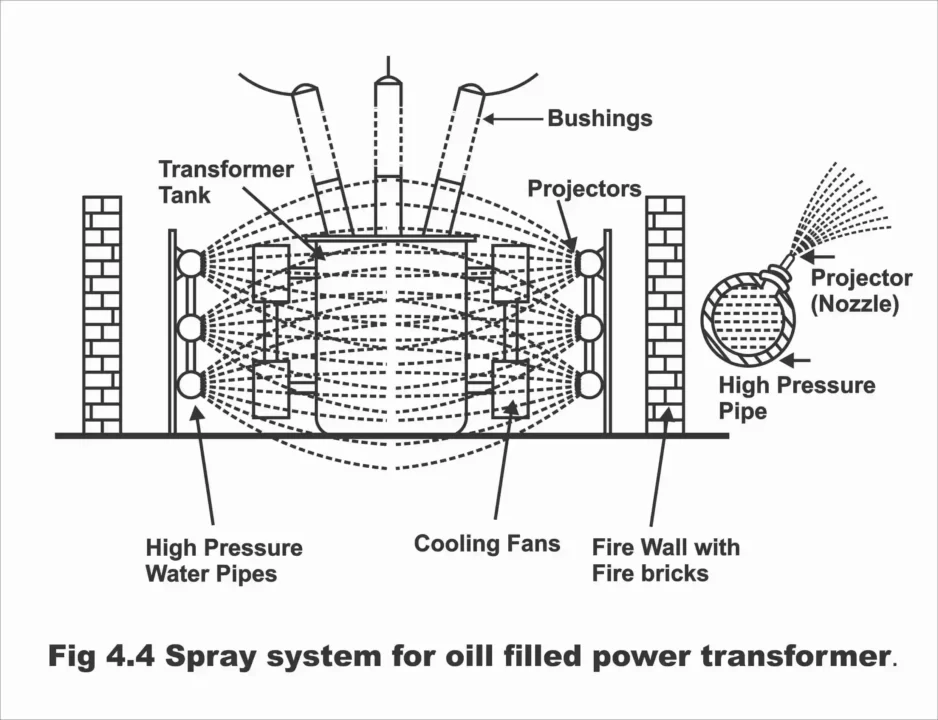
When a large piece of electrical equipment gets hot as a result of continuous application or emits smoke as a result of getting heated, the sensors fitted along this instrument (which are in the shape of a heat detector or smoke detector) sense an exceptionally increasing temperature or smoke emitting through the instrument. This signal received from a sensor or detector is delivered onto the controlling circuit after getting amplified. This servo mechanism-based control circuit receives a contingent situation signal and delivers it to the relay, which operates and opens the solenoid water valve set along with the water pump and the water pump starts to operate. As a result of the operation of the water pump, water starts sprinkling in pressure and falls on the heated or smoke-emitting installation in the form of multiple sprinkles. As a result, its temperature falls quickly. After temperature restores to a normal level or when smoke ceases, the solenoid water valve and water pump closed automatically. Thus, sprinklers stop operating until a time when the temperature of an electrical installation does not increase again beyond a certain limit. In figure 4.4, a sprinkler system fitted along an oil-filled power transformer has been illustrated.
Figure 4.4 – spray system for oil-filled power transformer
Smoke Alarm
An alarm that only senses the presence of smoke instead of heat operation, (i.e., which starts ringing upon sensing smoke), is called a smoke alarm. This type of alarm is only used under special conditions. Sometimes, the operation of this type of alarm causes inconvenience, because, in the absence of any type of fire, this alarm starts ringing even after sensing a very low quantity of smoke. This alarm is so sensitive that if a person present in the office starts smoking a cigarette, it starts to ring even then, though this smoke is not caused by any type of fire. To avoid such an inconvenience, now modern type alarms are being designed, along which a switch is administered to set their sensitivity. Through this switch, any prospective awkward situation can be averted by means of reducing their sensitivity or setting up the sensitivity on some suitable level.
Figure 4.5 – photoelectric cell type smoke detector
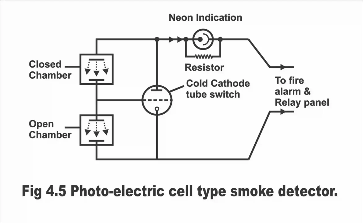
A smoke alarm consists of an ionization detector, wherein two chambers have been made. One of the chambers consists of a low-strength radioactive material and two electrodes. This radioactive material conducts through the air so that less current can pass between the electrodes. The quantity of current changes with the nature of gas passing through the chamber (i.e., quantity of current can be changed by changing the nature of the gas), and as soon as some combustible type of thing infiltrates through the air, a rapid and sudden change occurs in the quantity of current passing between the electrodes. The other end of the ionization detector remains completely sealed so that the current passing through it does not change. As long as the quantity of current passing through these chambers remains equal, no output is received (that’s output remains zero in case of an equivalent quantity of current passing through both the chambers). As soon as smoke mixes with the air passing through one of the chambers, the quantity of current between the electrodes mounted on this chamber tends to change. Resultantly, a difference occurs between the quantity of current flowing through both chambers (i.e., currents become unstable) as a result, a net output is received. The output received as a result of the difference in the currents, is used to operate a transistor switch mounted in the detector’s path. As such, the smoke alarm starts to ring as soon as the transistor switch turns ON.
Uses
A smoke alarm is used only in such places, buildings, or factories, where there is a danger of any kind of damage due to the existence of smoke. In figure 4.5, a photoelectric cell-type smoke detector circuit has been illustrated based on ionization chamber operation.
Burglar Alarm
The alarm, which is used in important and sensitive buildings, where greater security is necessary, for protection against dacoity, burglary, and pilferage, is called a burglar alarm. This type of alarm is mostly used in ammunition depots, sensitive government organizations, banks and jeweler’s shops, etc. Based on operation, burglar alarms can be divided into the following two types of circuits or systems.
(1). Open circuit burglar alarm
(2). Closed-circuit burglar alarm
The open-circuit burglar alarm works on the principle of an open circuit. This is a simple and common type of a burglar alarm, the electrical circuit of which normally tends to remain open and as soon as a window or door opens, both contacts existing on the detector circuit connects, and thus, the alarm starts ringing. The advantage of this type of open circuit alarm is that current flows through the circuit only when contacts connect or close. Sometimes, a switch is also included in the alarm circuit, so that an authorized person can open doors and windows without the ringing of the alarm during the daytime. The greatest disadvantage of this type of circuit is that no visible indication is received about the breaking or cutting of any one wire of the detector contacts, therefore circuit does not operate (that becomes useless) and resultantly, the alarm does not run.
The closed-circuit burglar alarm operates on the principle of a closed circuit and owing to its immense popularity, it is very commonly used. As the alarm name suggests, its electrical circuit normally tends to be closed and the alarm rings only when its detector circuit, breaks or opens as a result of the opening of the door or window. As a low quantity of current continuously flows through a relay coil or automatic switch in a closed circuit, which keeps the alarm circuit open (so that the alarm does not ring), therefore as soon as the detector circuit breaks as a result of the opening of the doors or windows or cutting of the wires, alarm circuits contacts close and the alarm starts to ring. As compared to an open circuit, the advantage of a closed circuit is that breaking or cutting of wires can clearly be noticed upon disconnection of the detector’s contacts due to the ringing of an alarm.
A basic alarm circuit consists of the following components;
(1). Alarm contacts
(2). Relay
(3). Batteries
(4). Sounder or bell
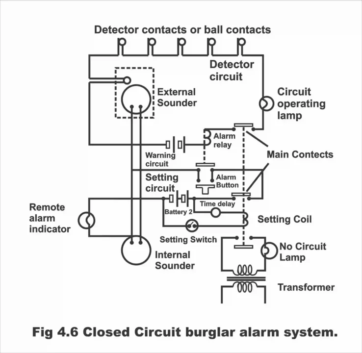
However, apart from the aforementioned accessories, some extra features and components are also added to most of the circuits. This has been demonstrated by a closed-circuit burglar alarm system vide figure 4.6. To understand this system shown in the figure easily, it has been divided into the following three sections;
(1). Setting circuit
(2). Detector circuit
(3). Warning circuit
Setting Circuit
This circuit consists of a setting switch, battery number 2, a time delay switch, and a setting coil. When the setting circuit is closed or turned ON, the time delay switch activates or energizes (i.e., it starts operation) and after a brief pre-set interval, during which an operator may leave the building, the setting coil energizes. This energized setting coil, closes the main contacts of the detector as well as the alarm or the warning circuit. As a result of energizing the setting coil, contacts of the no circuit indicator on the transformer, tend to open (that’s the lamp installed on the no circuit turns OFF). Remember that no circuit indicator illuminates only when the alarm circuit is OFF.
Detector Circuit
This type of circuit consists of pairs of several detector contacts mounted in a series, battery number 1, alarm relay, main contacts, and circuit operating indicator. When the main contacts join (i.e., close), the current starts flowing from the battery towards the alarm relay, as a result of which the alarm relay energizes. This alarm relay after energizing, keeps the alarm contacts existing on the warning circuit, open. As long as the circuit remains complete, the circuit operating lamp or indicator remains irradiated. However, if the circuit wires cut or break, or a pair of detector contacts disconnect, in such a situation alarm relay coil de-energizes. As a result, alarm contacts close (i.e., join together). One pair of the detector contacts is connected to an outer bell or sounder to stop interference. Remember that detector points are set at a place where there is no danger of any kind of interference. For example, in the doors, windows, etc.
Figure 4.6 – closed-circuit burglar alarm system
Warning Circuit
This type of circuit consists of main contacts, battery number 2, internal and external sounders, remote alarm indicator, and alarm button. When the alarm button is pushed, or when an alarm relay closes alarm contacts, then both the remote alarm indicator as well as the sounders are activated (i.e., they operate). Remote alarm indicator helps police or security company with the supervision of this whole system.
The object behind using batteries in this system is to keep the entire system independent of the main supply so that in case of failure of supply or cutting of the wires of the main supply, the security system does not fail. In other words, batteries are used in this system to protect the entire system from failure.
Uses
A burglar alarm system is used in all those places where round the clock high security is imminent, e.g., banks and jeweler’s shops, etc.
Alternative Explanation of Burglar Alarm
In order to protect precious belongings, documents, and cash from a burglar, the alarm system which is installed in important buildings for security purposes, is called a burglar alarm. This alarm system is commonly used in sensitive government organizations, banks and jeweler’s shops, etc. This alarm is normally set on a door or window frame through a door-type contact with a ball above it, which connects the contacts together via the window or door pressure. In this way, the alarm circuit remains closed or energized persistently. The burglar alarm basically consists of two types of circuits i.e., an open circuit burglar alarm and a closed-circuit burglar alarm. An open-circuit burglar alarm is a simple type of alarm, which normally consists of an open circuit series (i.e., its electrical circuit normally remains open). The open-circuit burglar alarm rings when the door type contact closes upon opening of the door or window. In figure 4.7,

the contact of a burglar alarm has been illustrated. The disadvantage of this type of alarm system is that when any of its wires cuts accidentally or intentionally, an alarm will not ring. Moreover, there is no clear indication of anyone or both wires of the circuit getting disconnected from the circuit. That’s why wires in an open circuit burglar alarm system are concealed very carefully. Moreover, they are also checked at regular intervals so that alarm operation can be ensured.
Contrary to the open circuit burglar alarm, like the electrical circuit of a closed-circuit burglar alarm always remains closed or energized (i.e., the alarm relay existing within this circuit always remains energized), therefore, as a result of cutting or breaking of wires or opening of the door or window wherein a door type burglar alarm contact or ball contact has been fixed, an alarm starts to ring. As such, this alarm system is more popular and commonly used. In figure 4.8, a closed-circuit burglar diagram has been illustrated.
Figure 4.8- closed-circuit burglar alarm
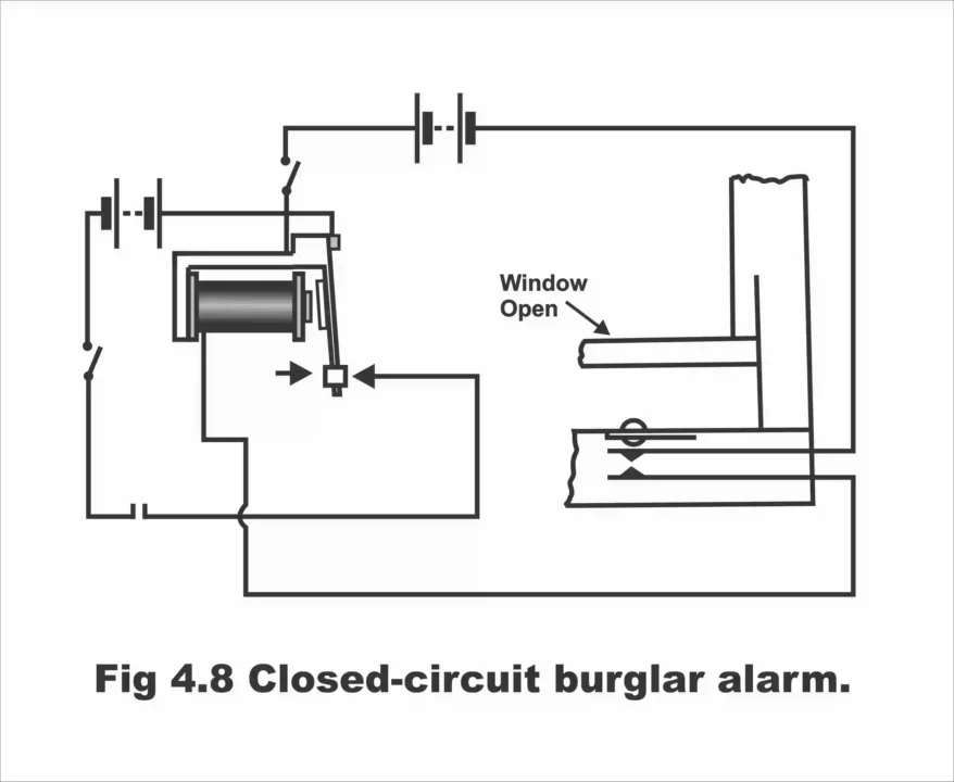
Remember that relay contact fitted on closed-circuit remains closed as long as the window remains shut due to the window pressure on the ball., as has been demonstrated in the figure. However, as soon as a window is opened or pushed up, the contact opens. So long as the window remains shut, current continuously flows through the alarm circuit, owing to which relay armature stands opposite to the magnetic poles (i.e., long looking relay armature’s contact, does not touch the magnetic pole of the magnetic coil, because same type poles repulse each other). Thus, the bell circuit remains open (i.e., the alarm does not run). As soon as the window is pushed up or opened, as has been illustrated in the figure, the relay gets de-energized or de-magnetic and the relay’s armature returns and connects with the contact post through a spring or sets up a contact. As such, the bell or alarm circuit completes and the alarm starts ringing. So, whenever the alarm’s wires are cut, or the window or door is opened, the relay operates, and an alarm starts ringing.
The object behind using batteries in a closed-circuit burglar alarm is to keep this entire system free from the main supply so that the system does not fail as a result of a failure of supply or cutting off the main supply’s wires. However, a disadvantage of this circuit is that relay battery is used continuously in this circuit, except during the daytime, if it is turned OFF through a day switch illustrated in the circuit. The high utilization defect of the batteries can be removed through the application of a high resistance relay, owing to which the current quantity reduces up to 3mA.
Next Topic: Working and Construction of Intercom System
Previous Topic: Ratings of Equipment Used in Substations
For electronics and programming related projects visit my YouTube channel.
Discover more from Electronic Clinic
Subscribe to get the latest posts sent to your email.