ESP32-C3 Analog Smart Watch Using LVGL, SquareLine Studio, and CrowPanel
Last Updated on January 4, 2025 by Engr. Shahzada Fahad
Table of Contents
ESP32-C3 Analog Smart Watch:
ESP32-C3 Analog Smart Watch Using LVGL, SquareLine Studio, and CrowPanel- This is my 4th article in the Smart Watch programming series using the CrowPanel ESP32-C3 1.28-inch IPS Capacitive Touch Display. In Part 3, we designed a digital watch using a background image designed in Figma as the watch face. Before reading today’s article, I highly recommend you read the previous article, as it explains how to add a screen, use a custom watch face, import and create custom fonts, add and name labels, and fix the most common errors.
In today’s article, we will continue with the same project, add a 3rd screen, and create an analog watch. After reading this article, you will learn how to add multiple screens, switch between screens, and animate hour and minute hands.
So, without any further delay, let’s get started!!!

So far, we have designed two GUI’s; one for the Counter and the other one for the digital watch. For the analog watch, we are going to add a third screen. Go to the Widgets Tab, scroll down, and click on Screen.

On the Inspector tab, go to STYLE (MAIN) and set the background radius to 240 and set the background color.

For the digital watch, I designed the watch face in Figma. However, this time I used Adobe Photoshop to create the watch face, hour hand, and minute hand.

To ensure a transparent background, I saved these images as PNG files. Now, let’s import all three images into SquareLine Studio. Simply, click the ADD FILE INTO ASSETS button and select the files you want to import.
As you can see, all three images have been added to the Assets. Let’s add the watch face image.

Next, on the inspector tab go to the background and select the watch face you want to set as the background. You can see the image has been successfully set as the watch face.
Next, to add the hour and minute hands, we will use the image widget. Simply, click the image widget, the image box will be added on the screen3, then on the right side select the watch hand. As you can see in the image below, the hour hand has been added. Now, follow the same steps for adding the minute hand.

Now, name the image widgets so we can easily identify them on the Arduino side.

I named the two image widgets as;
Imagehourhand and imageminutehand.
In the previous video, I explained in detail how to switch between two screens. Let me also play the simulation so you can clearly see and understand what I am about to explain.

As of now, you can see I can only switch between two screens: Screen1 and Screen2. Screen3 doesn’t show up because I haven’t set the screen change action for Screen3 yet.
While Screen2 is selected, you can see there’s only one event. Its trigger type is set to GESTURE_RIGHT, and the action is set to Screen1. This means that when I swipe my finger to the right on the display, Screen1 will show up.
Now, let’s add another event so that when I swipe my finger to the left, Screen3 will show up. Let’s do it!
Set the Trigger type to GESTURE_LEFT.
Next, set the Action type to CHANGE SCREEN.
Then click on the ADD button.
Select Screen3.
Now, repeat the same steps for Screen3.
While the Screen3 is selected, click on the ADD EVENT.
Set the Trigger type to GESTURE_RIGHT.
Next, set the Action type to CHANGE SCREEN.
Then click on the ADD button.
Select Screen2.
After adding the Change Screen events, play the simulation to ensure everything is working.

Great! It’s working.
Now, save the project and Export the UI files. As I explained in my previous articles and videos, each time you generate the UI files, you have to copy all the files and paste them into the same Arduino project folder.
After copying and pasting the newly generated UI files. Then go ahead and open the main Arduino file.
ESP32-C3 Analog Smart Watch Code:
|
1 2 3 4 5 6 7 8 9 10 11 12 13 14 15 16 17 18 19 20 21 22 23 24 25 26 27 28 29 30 31 32 33 34 35 36 37 38 39 40 41 42 43 44 45 46 47 48 49 50 51 52 53 54 55 56 57 58 59 60 61 62 63 64 65 66 67 68 69 70 71 72 73 74 75 76 77 78 79 80 81 82 83 84 85 86 87 88 89 90 91 92 93 94 95 96 97 98 99 100 101 102 103 104 105 106 107 108 109 110 111 112 113 114 115 116 117 118 119 120 121 122 123 124 125 126 127 128 129 130 131 132 133 134 135 136 137 138 139 140 141 142 143 144 145 146 147 148 149 150 151 152 153 154 155 156 157 158 159 160 161 162 163 164 165 166 167 168 169 170 171 172 173 174 175 176 177 178 179 180 181 182 183 184 185 186 187 188 189 190 191 192 193 194 195 196 197 198 199 200 201 202 203 204 205 206 207 208 209 210 211 212 213 214 215 216 217 218 219 220 221 222 223 224 225 226 227 228 229 230 231 232 233 234 235 236 237 238 239 240 241 242 243 244 245 246 247 248 249 250 251 252 253 254 255 256 257 258 259 260 261 262 263 264 265 266 267 268 269 270 271 272 273 274 275 276 277 278 279 280 281 282 283 284 285 286 287 288 289 290 291 292 293 294 295 296 297 298 299 300 301 302 303 304 305 306 307 308 309 310 311 312 313 314 315 316 317 318 319 320 321 322 323 324 325 326 327 328 329 330 331 332 333 334 335 336 337 338 339 340 341 342 343 344 345 346 347 348 349 350 351 352 353 354 355 356 357 358 359 360 361 362 363 364 365 366 367 368 369 370 371 372 373 374 375 376 377 378 379 380 381 382 383 384 385 386 387 388 389 390 391 392 393 394 395 396 397 398 399 400 401 402 403 404 405 406 407 408 409 |
#define LGFX_USE_V1 #include <WiFi.h> #include "Arduino.h" #include <lvgl.h> #include <LovyanGFX.hpp> #include <Ticker.h> #include "CST816D.h" #include "do_mian.h" #include "ui.h" #include <Preferences.h> #include "I2C_BM8563.h" #define I2C_SDA 4 #define I2C_SCL 5 #define TP_INT 0 #define TP_RST -1 int counter = 0; // For analog watch int h = 0; int m = 0; int s = 0; //encoder #define ENCODER_A_PIN 19 #define ENCODER_B_PIN 18 #define SWITCH_PIN 8 //Custom key pins #define Custom_PIN 1 long position = 0; long position_tmp = 0; bool switchPressed = false; #define PI4IO_I2C_ADDR 0x43 I2C_BM8563 rtc(I2C_BM8563_DEFAULT_ADDRESS, Wire); I2C_BM8563_DateTypeDef dateStruct; I2C_BM8563_TimeTypeDef timeStruct; #define off_pin 35 #define buf_size 120 //Alarm switch sign int fal = 0; //Indicates whether the alarm has gone off int fal1 = 0; uint32_t hourValue = 0; uint32_t minuteValue = 0; class LGFX : public lgfx::LGFX_Device { lgfx::Panel_GC9A01 _panel_instance; lgfx::Bus_SPI _bus_instance; public: LGFX(void) { { auto cfg = _bus_instance.config(); cfg.spi_host = SPI2_HOST; cfg.spi_mode = 0; cfg.freq_write = 80000000; cfg.freq_read = 20000000; cfg.spi_3wire = true; cfg.use_lock = true; cfg.dma_channel = SPI_DMA_CH_AUTO; cfg.pin_sclk = 6; cfg.pin_mosi = 7; cfg.pin_miso = -1; cfg.pin_dc = 2; _bus_instance.config(cfg); _panel_instance.setBus(&_bus_instance); } { auto cfg = _panel_instance.config(); cfg.pin_cs = 10; cfg.pin_rst = -1; cfg.pin_busy = -1; cfg.memory_width = 240; cfg.memory_height = 240; cfg.panel_width = 240; cfg.panel_height = 240; cfg.offset_x = 0; cfg.offset_y = 0; cfg.offset_rotation = 0; cfg.dummy_read_pixel = 8; cfg.dummy_read_bits = 1; cfg.readable = false; cfg.invert = true; cfg.rgb_order = false; cfg.dlen_16bit = false; cfg.bus_shared = false; _panel_instance.config(cfg); } setPanel(&_panel_instance); } }; LGFX tft; CST816D touch(I2C_SDA, I2C_SCL, TP_RST, TP_INT); /*Change to your screen resolution*/ static const uint32_t screenWidth = 240; static const uint32_t screenHeight = 240; static lv_disp_draw_buf_t draw_buf; static lv_color_t buf[2][screenWidth * buf_size]; #if LV_USE_LOG != 0 /* Serial debugging */ void my_print(lv_log_level_t level, const char *file, uint32_t line, const char *fn_name, const char *dsc) { Serial.printf("%s(%s)@%d->%s\r\n", file, fn_name, line, dsc); Serial.flush(); } #endif /* Display flushing */ void my_disp_flush(lv_disp_drv_t *disp, const lv_area_t *area, lv_color_t *color_p) { if (tft.getStartCount() == 0) { tft.endWrite(); } tft.pushImageDMA(area->x1, area->y1, area->x2 - area->x1 + 1, area->y2 - area->y1 + 1, (lgfx::swap565_t *)&color_p->full); lv_disp_flush_ready(disp); /* tell lvgl that flushing is done */ } /*Read the touchpad*/ void my_touchpad_read(lv_indev_drv_t *indev_driver, lv_indev_data_t *data) { bool touched; uint8_t gesture; uint16_t touchX, touchY; touched = touch.getTouch(&touchX, &touchY, &gesture); if (!touched) { data->state = LV_INDEV_STATE_REL; } else { data->state = LV_INDEV_STATE_PR; /*Set the coordinates*/ data->point.x = touchX; data->point.y = touchY; } } Ticker ticker; //Extended IO function void init_IO_extender() { Wire.beginTransmission(PI4IO_I2C_ADDR); Wire.write(0x01); // test register Wire.endTransmission(); Wire.requestFrom(PI4IO_I2C_ADDR, 1); uint8_t rxdata = Wire.read(); Serial.print("Device ID: "); Serial.println(rxdata, HEX); Wire.beginTransmission(PI4IO_I2C_ADDR); Wire.write(0x03); // IO direction register Wire.write((1 << 0) | (1 << 1) | (1 << 2) | (1 << 3) | (1 << 4)); // set pins 0, 1, 2 as outputs Wire.endTransmission(); Wire.beginTransmission(PI4IO_I2C_ADDR); Wire.write(0x07); // Output Hi-Z register Wire.write(~((1 << 0) | (1 << 1) | (1 << 2) | (1 << 3) | (1 << 4))); // set pins 0, 1, 2 low Wire.endTransmission(); } void set_pin_io(uint8_t pin_number, bool value) { Wire.beginTransmission(PI4IO_I2C_ADDR); Wire.write(0x05); // test register Wire.endTransmission(); Wire.requestFrom(PI4IO_I2C_ADDR, 1); uint8_t rxdata = Wire.read(); Serial.print("Before the change: "); Serial.println(rxdata, HEX); Wire.beginTransmission(PI4IO_I2C_ADDR); Wire.write(0x05); // Output register if (!value) Wire.write((~(1 << pin_number)) & rxdata); // set pin low else Wire.write((1 << pin_number) | rxdata); // set pin high Wire.endTransmission(); Wire.beginTransmission(PI4IO_I2C_ADDR); Wire.write(0x05); // test register Wire.endTransmission(); Wire.requestFrom(PI4IO_I2C_ADDR, 1); rxdata = Wire.read(); Serial.print("after the change: "); Serial.println(rxdata, HEX); } //RTC function void RTC_init() { rtc.begin(); // Set custom time // I2C_BM8563_TimeTypeDef timeStruct; // timeStruct.hours = 11; // Hour (0 - 23) // timeStruct.minutes = 59; // Minute (0 - 59) // timeStruct.seconds = 0; // Second (0 - 59) // rtc.setTime(&timeStruct); // // I2C_BM8563_DateTypeDef dateStruct; // dateStruct.weekDay = 3; // Weekday (0 - 6, where 0 is Sunday) // dateStruct.month = 1; // Month (1 - 12) // dateStruct.date = 24; // Day of the month (1 - 31) // dateStruct.year = 2024; // Year // rtc.setDate(&dateStruct); } //Encoder function void updateEncoder() { static int previousState = 0; static int flag_A = 0; static int flag_C = 0; int currentState = (digitalRead(ENCODER_A_PIN) << 1) | digitalRead(ENCODER_B_PIN); if ((currentState == 0b00 && previousState == 0b01) || (currentState == 0b01 && previousState == 0b11) || (currentState == 0b11 && previousState == 0b10) || (currentState == 0b10 && previousState == 0b00)) { // foreward // if (switchPressed) { flag_A++; if (flag_A == 50) { flag_A = 0; flag_C = 0; // position++; // position_tmp=position; position_tmp = 1; } // flag_C=0; // } } else if ((currentState == 0b01 && previousState == 0b00) || (currentState == 0b11 && previousState == 0b01) || (currentState == 0b10 && previousState == 0b11) || (currentState == 0b00 && previousState == 0b10)) { // reversal // if (switchPressed) { flag_C++; if (flag_C == 50) { // position--; flag_C = 0; flag_A = 0; // position_tmp=position; position_tmp = 0; } // flag_A=0; // } } previousState = currentState; } void switchPressedInterrupt() { switchPressed = !switchPressed; } void setup() { Serial.begin(115200); /* prepare for possible serial debug */ Serial.println("I am LVGL_Arduino"); Wire.begin(4, 5); init_IO_extender(); delay(100); set_pin_io(3, true); set_pin_io(4, true); pinMode(ENCODER_A_PIN, INPUT_PULLUP); pinMode(ENCODER_B_PIN, INPUT_PULLUP); pinMode(SWITCH_PIN, INPUT_PULLUP); pinMode(Custom_PIN, INPUT); attachInterrupt(digitalPinToInterrupt(ENCODER_A_PIN), updateEncoder, CHANGE); attachInterrupt(digitalPinToInterrupt(ENCODER_B_PIN), updateEncoder, CHANGE); attachInterrupt(digitalPinToInterrupt(SWITCH_PIN), switchPressedInterrupt, FALLING); // ticker.attach(1, tcr1s); tft.init(); tft.initDMA(); tft.startWrite(); tft.setColor(0, 0, 0); tft.fillScreen(TFT_BLACK); delay(200); if (is_touch == 1) { touch.begin(); } lv_init(); #if LV_USE_LOG != 0 //lv_log_register_print_cb(my_print); /* register print function for debugging */ #endif lv_disp_draw_buf_init(&draw_buf, buf[0], buf[1], screenWidth * buf_size); /*Initialize the display*/ static lv_disp_drv_t disp_drv; lv_disp_drv_init(&disp_drv); /*Change the following line to your display resolution*/ disp_drv.hor_res = screenWidth; disp_drv.ver_res = screenHeight; disp_drv.flush_cb = my_disp_flush; disp_drv.draw_buf = &draw_buf; lv_disp_drv_register(&disp_drv); /*Initialize the (dummy) input device driver*/ if (is_touch == 1) { static lv_indev_drv_t indev_drv; lv_indev_drv_init(&indev_drv); indev_drv.type = LV_INDEV_TYPE_POINTER; indev_drv.read_cb = my_touchpad_read; lv_indev_drv_register(&indev_drv); } #if 0 /* Create simple label */ lv_obj_t *label = lv_label_create( lv_scr_act() ); lv_label_set_text( label, "Hello Arduino! (V8.0.X)" ); lv_obj_align( label, LV_ALIGN_CENTER, 0, 0 ); #else /* Try an example from the lv_examples Arduino library make sure to include it as written above. lv_example_btn_1(); */ // uncomment one of these demos // lv_demo_widgets(); // OK // lv_demo_benchmark(); // OK // lv_demo_keypad_encoder(); // works, but I haven't an encoder // lv_demo_music(); // NOK // lv_demo_printer(); // lv_demo_stress(); // seems to be OK ui_mian(); // watch #endif Serial.println("Setup done"); // delay(200); set_pin_io(2, true); pinMode(3, OUTPUT); digitalWrite(3, LOW); // pinMode(0, INPUT); // Get RTC RTC_init(); rtc.getDate(&dateStruct); rtc.getTime(&timeStruct); } //void Watch_Function(void *param) void loop() { lv_timer_handler(); /* let the GUI do its work */ lv_label_set_text(ui_lblCounter, String(counter).c_str()); rtc.getTime(&timeStruct); lv_label_set_text(ui_lblHour, String(timeStruct.hours).c_str()); lv_label_set_text(ui_lblminutes, String(timeStruct.minutes).c_str()); lv_label_set_text(ui_lblseconds, String(timeStruct.seconds).c_str()); /****************** For Analog Watch ****************/ h = timeStruct.hours; m = timeStruct.minutes; // s = timeStruct.seconds * 60 % 3600; //Initializing the alarm page from the RTC // lv_img_set_angle(ui_shand, s); // lv_img_set_angle(ui_shand2, s); lv_img_set_angle(ui_imageminutehand, m * 60); lv_img_set_angle(ui_imagehourhand, h * 300 + m / 12 * 60); lv_img_set_angle(ui_imageminutehand, m * 60); lv_img_set_angle(ui_imagehourhand, h * 300 + m / 12 * 60); } void ResetCounter(lv_event_t * e) { counter = 0; } void incrementCounter(lv_event_t * e) { counter++; } |
In Part 3, I already explained where to find the screen properties, how to enable support for large fonts, and how to locate all the variables. I recommend reading my previous article to learn how to avoid errors.
There is just one thing you need to do every time you generate new UI files: change LV_COLOR_16_SWAP from 0 to 1.
Let me tell you, if you want to make everything easier, simply download this template folder. It includes all the files with all errors already fixed for you.
Practical Demonstration:

On the first screen, you can see a fully functional counter. I can increment the counter using the + button and long-press the Reset button to reset the counter value back to zero.
Now, if I swipe my finger to the left, Screen2 will appear, showing a digital watch with a custom watch face designed in Figma.

There are many online and offline software tools you can use to design amazing futuristic watch faces, or you can simply purchase ready-made watch faces.
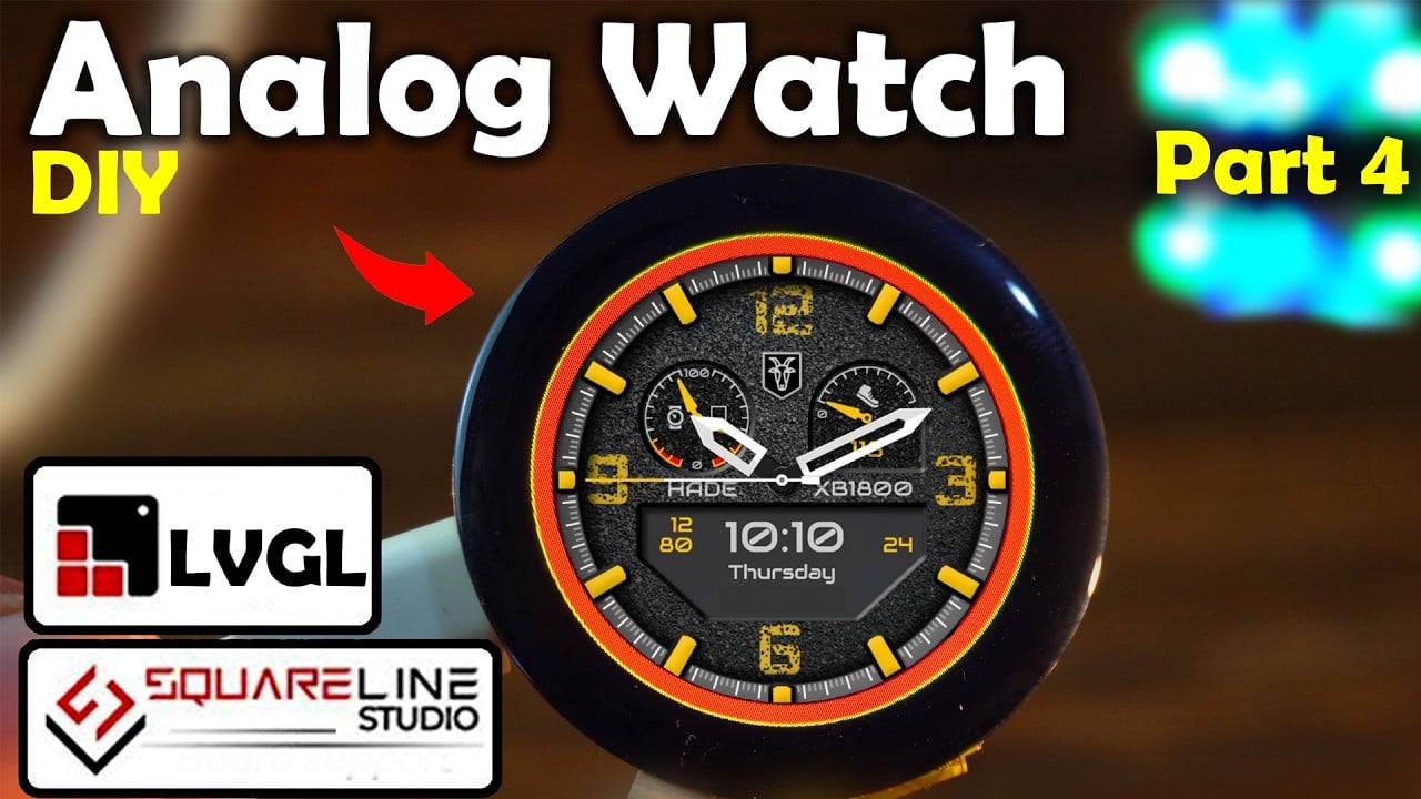
If I swipe my finger to the left one more time, Screen3 will appear, showcasing our analog watch.

I am sure you now have an idea of how to use and animate PNG images. I know the design isn’t too attractive, and you can already see the colors are slightly distorted. This is because I used images with 32-bit color depth, while the CrowPanel uses 16-bit color depth. If these images were 16-bit, this analog watch would look much better.

So, here’s a pro tip: use images with 16-bit color depth for better results.
So, that’s all for now!
Watch Video Tutorial:
Discover more from Electronic Clinic
Subscribe to get the latest posts sent to your email.


