ESP32-S3 Geek and Arduino IDE- Getting Started Tutorial
Last Updated on April 7, 2025 by Engr. Shahzada Fahad
Table of Contents
ESP32-S3 Geek Introduction:
ESP32-S3 Geek and Arduino IDE- Getting Started Tutorial- Today, we will look at something very cool the Waveshare ESP32-S3 Geek Development board.
You can carry this with you, just like a normal USB flash drive. And whenever you want, just connect it to your laptop or PC, and you’ll be able to control anything; locally, or from anywhere in the world; and at the very same time, monitor all kinds of sensors too!
And all this is possible due to its onboard ESP32-S3R2 chip with Xtensa 32-bit LX7 dual-core processor, capable of running at 240 MHz.
Built-in 512KB SRAM, 384KB ROM, 2MB of on-chip PSRAM, and onboard 16MB Flash memory.
USB-A port, 1.14inch 240×135 pixels 65K color IPS LCD display, a TF card slot, a BOOT button, and other peripherals.
It supports 2.4GHz WiFi and BLE 5. The onboard 3-pin UART, 3-pin GPIO, and 4-pin I2C interface headers, bringing more possibilities for your project.
We will cover 4 examples. First we will start with easy ones; but make sure you watch until the end, because the last project is the most fun!
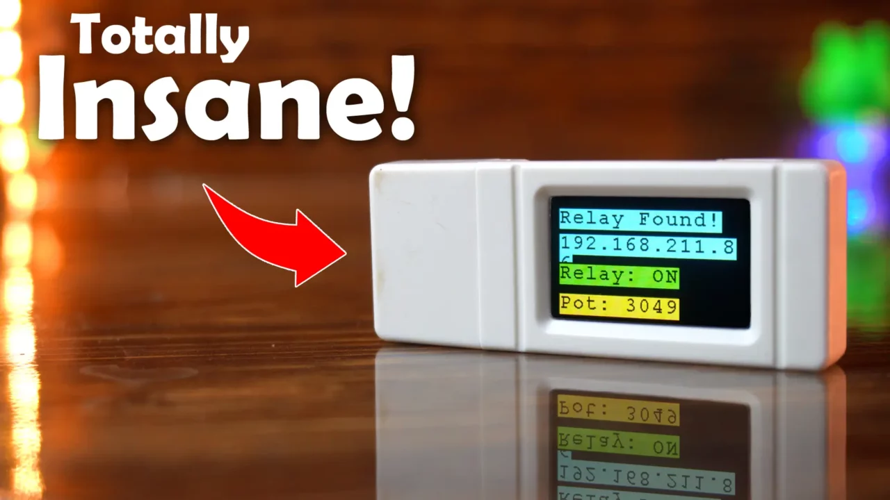
We are going to use the ESP32-S3 Geek to wirelessly control a load connected to a completely separate ESP32 board! And that’s not all! We will also be monitoring a sensor hooked up to that remote ESP32, streaming its value back, and showing it live on the ESP32-S3 Geek’s awesome display!
So, without any further delay let’s get started!!!
Amazon Links:
ESP32-S3 GEEK Development Board
Other Tools and Components:
ESP32 WiFi + Bluetooth Module (Recommended)
Arduino Nano USB C type (Recommended)
*Please Note: These are affiliate links. I may make a commission if you buy the components through these links. I would appreciate your support in this way!
Make sure you have a latest version of the Arduino IDE.
Let’s first start by installing the required libraries;
TFT_eSPI and
OneButton
Install TFT_eSPI and OnButton Library
- Open the Arduino IDE.
- Go to Sketch-> Include Library -> Manage Libraries.
- Search for “TFT_eSPI.
- Install the library by Bodmer.

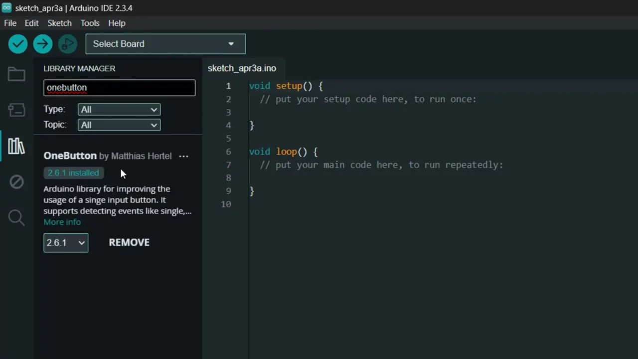
To install the “OneButton” library.
- While the Arduino IDE is open.
- Go to the menu: Sketch-> Include Library -> Manage Libraries.
- In the search box type: OneButton
- You should see several results. Look specifically for the one named “OneButton” by Matthias Hertel.
- Click on that library entry.
- Click the “Install”
- Wait for the installation to complete.
The libraries are installed and now we can start with the programming.
For this, you need to go to the product’s wiki page. In the Resource section, you can download the schematic for the ESP32-S3 Geek development board and the Demo folder, which contains many examples.
The 3rd and 4th example codes are not included because I programmed them myself. Anyway, you can also download the datasheets. And for basic examples, download the ESP32-S3 Geek Demo.
Inside the Demo folder, go to the Arduino folder, where you will find many examples. We will cover two examples from there, while the other two are my custom codes.
ESP32-S3 Geek Example 1:
If we go to the LCD folder, we will find two more examples. We need to run both. So, let’s first check the LCD_Button example.
Program:
|
1 2 3 4 5 6 7 8 9 10 11 12 13 14 15 16 17 18 19 20 21 22 23 24 25 26 27 28 29 30 31 32 33 34 35 36 37 38 39 40 41 42 43 44 45 46 47 48 49 50 51 52 53 54 55 56 57 |
#include <SPI.h> #include "LCD_Driver.h" #include "GUI_Paint.h" #include "image.h" #include "OneButton.h" #define PIN_INPUT 0 OneButton button(PIN_INPUT, true); char click = 1; void setup() { Serial.begin(115200); Config_Init(); LCD_Init(); LCD_Clear(BLACK); LCD_SetBacklight(1000); Paint_NewImage(LCD_WIDTH, LCD_HEIGHT, 0, BLACK); Paint_DrawImage(gImage_pic1, 0, 0, 135, 240); button.attachLongPressStart(LongPressStart, &button); button.attachClick(Click, &button); button.setLongPressIntervalMs(1000); } void loop() { // keep watching the push button: button.tick(); delay(10); } // this function will be called when the button started long pressed. void LongPressStart(void *oneButton) { analogWrite(DEV_BL_PIN, 0); } void Click(void *oneButton) { LCD_SetBacklight(1000); Paint_NewImage(LCD_WIDTH, LCD_HEIGHT, 0, BLACK); click++; if(click >= 4)click = 1; switch(click) { case 1: Paint_DrawImage(gImage_pic1, 0, 0, 135, 240); break; case 2: Paint_DrawImage(gImage_pic2, 0, 0, 135, 240); break; case 3: Paint_DrawImage(gImage_pic3, 0, 0, 135, 240); break; } } |
This is the main Arduino .ino program but there are several other .h and .cpp files which need to be placed inside the same folder with the .ino file. You can download the complete template folder from the product’s official page and also from my Patreon page; from where you can also download my custom programs.
Download all 4 examples from the Patreon Page.
While uploading the program select “ESP32S3 Dev Module” and don’t forget to select the correct communication port.
Practical demonstration:
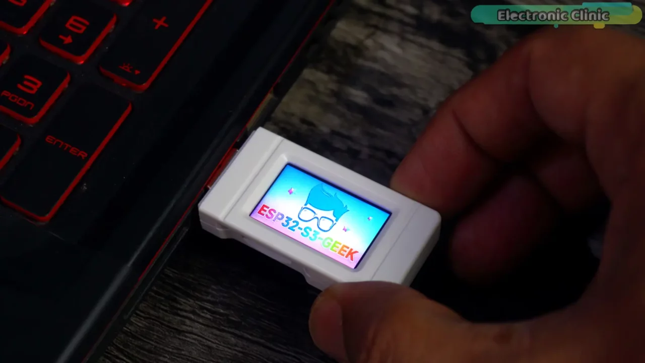
See how quickly we got this up and running in just a few minutes! With the boot button, I can switch between images effortlessly.
Now, let’s dive into the next example!
ESP32-S3 Geek Example 2:
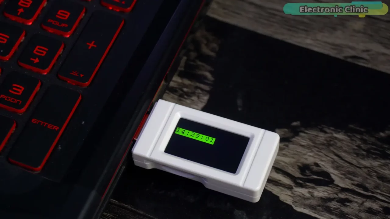
The purpose of this program is to display the time on the screen, updating every 2 seconds.
Program:
|
1 2 3 4 5 6 7 8 9 10 11 12 13 14 15 16 17 18 19 20 21 22 23 24 25 26 27 28 29 30 31 32 33 34 35 36 37 38 39 40 41 42 43 44 45 46 47 48 49 50 51 52 53 54 55 56 57 58 59 60 61 62 63 64 65 66 67 68 69 70 71 72 73 74 75 76 77 78 79 80 81 82 83 84 85 86 87 88 89 90 91 92 93 94 95 96 97 98 99 100 101 102 103 104 105 106 107 108 109 110 111 112 113 114 115 116 117 118 119 120 121 122 123 124 125 126 127 128 129 130 131 132 133 134 135 136 137 138 139 140 141 142 143 |
#include <WiFi.h> #include <HTTPClient.h> // Note: Not strictly needed for NTP time sync itself #include <time.h> #include <SPI.h> // Include the specific LCD and GUI libraries for your Waveshare display #include "LCD_Driver.h" #include "GUI_Paint.h" #include "image.h" // Assuming this holds font data or images const char* ssid = "fahad"; // Your WiFi SSID const char* password = "fahad123"; // Your WiFi Password const char* ntpServer = "pool.ntp.org"; // NTP server pool address // --- CORRECTED UTC OFFSET FOR PAKISTAN (PKT = UTC+5) --- const long utcOffsetInSeconds = 18000; // 5 hours * 60 mins * 60 secs = 18000 const int daylightOffset_sec = 0; // Pakistan does not observe DST currently void setup() { Serial.begin(115200); Serial.println("\n\n--- Pakistan Time Display (ESP32-S3-GEEK) ---"); // Initialize LCD using Waveshare specific functions Serial.print("Initializing LCD..."); Config_Init(); // Handles pin configuration based on LCD_Driver library LCD_Init(); // Initializes the LCD controller (e.g., GC9A01) LCD_SetBacklight(100); // Set backlight brightness (0-255 or similar, check library) // Initialize the drawing buffer // Parameters: Width, Height, Rotation (check options), Background Color Paint_NewImage(LCD_WIDTH, LCD_HEIGHT, 90, WHITE); // Using 90 degree rotation as example Paint_SetRotate(90); // Ensure GUI Paint rotation matches buffer if needed LCD_Clear(BLACK); // Clear physical screen to black initially Paint_Clear(BLACK); // Clear the image buffer to black Serial.println(" Done."); // Display WiFi Connecting message Paint_DrawString_EN(20, 50, "WiFi Connecting...", &Font20, WHITE, BLACK); // White text on Black bg // --- CORRECTED FUNCTION CALL --- //LCD_Display(Paint.Image); // Display the buffer content on the LCD Serial.print("Connecting to WiFi '"); Serial.print(ssid); Serial.print("'..."); WiFi.begin(ssid, password); while (WiFi.status() != WL_CONNECTED) { delay(500); Serial.print("."); } Serial.println(" Connected!"); // Display WiFi Connected message Paint_Clear(BLACK); // Clear buffer before drawing new text Paint_DrawString_EN(20, 50, "WiFi Connected", &Font20, GREEN, BLACK); // Green text on Black bg // --- CORRECTED FUNCTION CALL --- //LCD_Display(Paint.Image); // Display the buffer content on the LCD delay(1000); // Show message briefly // Configure time from NTP server Serial.print("Configuring time from NTP..."); configTime(utcOffsetInSeconds, daylightOffset_sec, ntpServer); // Wait for time synchronization Paint_Clear(BLACK); // Clear buffer Paint_DrawString_EN(20, 50, "Syncing Time...", &Font24, WHITE, BLACK); // White text on Black bg // --- CORRECTED FUNCTION CALL --- //LCD_Display(Paint.Image); // Display the buffer content on the LCD while (!time(nullptr)) { // time(nullptr) returns 0 until synced delay(500); Serial.print("."); } Serial.println(" Synced!"); // Display Time Synced message Paint_Clear(BLACK); // Clear buffer Paint_DrawString_EN(20, 50, "Time Synced!", &Font24, GREEN, BLACK); // Green text on Black bg // --- CORRECTED FUNCTION CALL --- //LCD_Display(Paint.Image); // Display the buffer content on the LCD delay(1000); // Show message briefly Serial.println("Setup complete. Starting clock display."); } void loop() { time_t now = time(nullptr); // Get current time as time_t object (seconds since epoch) struct tm timeinfo; // Structure to hold broken-down time components (hour, min, sec, day, month, year etc.) // Convert time_t to tm struct using the timezone configured in setup() localtime_r(&now, &timeinfo); char timeStr[9]; // Buffer for HH:MM:SS format (8 chars + null terminator) char dateStr[20]; // Buffer for Day Mon DD YYYY format (approx length) // Format time and date using strftime for precise control // See strftime documentation for format codes: https://www.cplusplus.com/reference/ctime/strftime/ strftime(timeStr, sizeof(timeStr), "%H:%M:%S", &timeinfo); // Format as 24-hour:Minute:Second strftime(dateStr, sizeof(dateStr), "%a %b %d %Y", &timeinfo); // Format as "DDD MMM DD YYYY" e.g., "Tue Jan 01 2024" // --- Drawing on the LCD Buffer --- // 1. Clear the display buffer before drawing the new time/date Paint_Clear(BLACK); // 2. Display Time // Calculate approximate center position for the time string // Note: Font size/width needs checking with your specific Font24 metrics int timeWidth = strlen(timeStr) * 16; // ESTIMATE: Font24 might be ~16px wide per char int timeX = (LCD_WIDTH - timeWidth) / 2; int timeY = 32; // Y position for the time if(timeX < 0) timeX = 0; // Prevent negative X coordinate Paint_DrawString_EN(timeX, timeY, timeStr, &Font24, GREEN, BLACK); // Draw time string // 3. Display Date // Calculate approximate center position for the date string // Note: Font size/width needs checking with your specific Font20 metrics int dateWidth = strlen(dateStr) * 10; // ESTIMATE: Font20 might be ~10px wide per char int dateX = (LCD_WIDTH - dateWidth) / 2; int dateY = 82; // Y position for the date if(dateX < 0) dateX = 0; // Prevent negative X coordinate Paint_DrawString_EN(dateX, dateY, dateStr, &Font20, WHITE, BLACK); // Draw date string // --- End Drawing --- // 4. Update the physical LCD screen with the modified buffer content // --- CORRECTED FUNCTION CALL --- //LCD_Display(Paint.Image); // Print formatted time to Serial Monitor for debugging purposes Serial.print("Current Time (PKT): "); Serial.print(dateStr); Serial.print(" "); Serial.println(timeStr); // Wait for approximately one second before updating again delay(1000); } // Note: The functions removeNewlineCharacters and extractDateAndTime from your original // code are no longer needed because we use strftime for formatting. |
A few words about the Code:
|
1 2 3 |
const char* ssid = "fahad"; // Your WiFi SSID const char* password = "fahad123"; // Your WiFi Password |
This is my SSID and password, but you need to enter your own SSID and password.
|
1 2 3 4 5 6 7 |
const char* ntpServer = "pool.ntp.org"; // NTP server pool address // --- CORRECTED UTC OFFSET FOR PAKISTAN (PKT = UTC+5) --- const long utcOffsetInSeconds = 18000; // 5 hours * 60 mins * 60 secs = 18000 const int daylightOffset_sec = 0; // Pakistan does not observe DST currently |
Alright, so to make sure my ESP32 gets the accurate time, first I need to tell it where to find it on the internet. For that, I am using “pool.ntp.org”, which is a standard address for Network Time Protocol servers; that’s what this ntpServer line sets up. Now, the time we get from the internet is usually standard UTC time, but I want the display to show the local time for Pakistan (PKT), which is 5 hours ahead. So, I need to tell the system that offset in seconds; 5 hours works out to 18,000 seconds, which is the value I have assigned to utcOffsetInSeconds. Lastly, since Pakistan doesn’t currently observe Daylight Saving Time, I have set the daylightOffset_sec to 0, ensuring the time doesn’t automatically adjust for summer hours.
Practical Demonstration:
The time updates every 2 seconds.
Now, let’s dive into the next example!
ESP32-S3 Geek Example 3:
Now, let’s get hands-on with the ESP32-S3 Geek Development Board by connecting an I2C-supported component to its I2C interface.
Why not connect an I2C-supported SSD1306 OLED display module to the board? This way, we can print text on two displays at the same time! If you prefer, you can also connect a sensor instead of the OLED display module.
Interfacing:
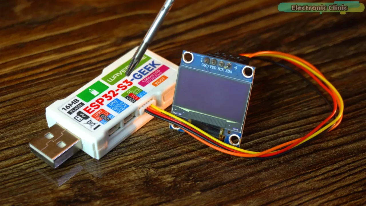
Simply connect the OLED display module’s VCC and GND to 3.3V and GND, and connect its SCL and SDA to the ESP32-S3 Geek Module’s SCL and SDA pins—and that’s it for the connections.
Program:
The purpose of this program is not only to print the text ‘Electronic Clinic’ on the ESP32-S3 Geek display and also send the status of the BOOT button to the SSD1306 OLED display module.
|
1 2 3 4 5 6 7 8 9 10 11 12 13 14 15 16 17 18 19 20 21 22 23 24 25 26 27 28 29 30 31 32 33 34 35 36 37 38 39 40 41 42 43 44 45 46 47 48 49 50 51 52 53 54 55 56 57 58 59 60 61 62 63 64 65 66 67 68 69 70 71 72 73 74 75 76 77 78 79 80 81 82 83 84 85 86 87 88 89 90 91 92 93 94 95 96 97 98 99 100 101 102 103 104 105 106 107 108 109 110 111 112 113 114 115 116 117 118 119 120 121 122 123 124 125 126 127 128 129 130 131 132 133 134 135 136 137 138 139 140 141 142 143 144 145 146 147 148 149 150 |
/** * Displays "Electronic Clinic" on the ESP32-S3-GEEK's built-in LCD. * Displays the status of the BOOT button (GPIO 0) ("Pressed"/"Released") * on an external SSD1306 OLED display connected via I2C. Programmer: Engr. Shahzada Fahad website: https://www.electroniclinic.com/ YouTube Channel: Electronic Clinic */ #include <SPI.h> // May be needed by the LCD library #include <Wire.h> // Needed for I2C (SSD1306) #include <Adafruit_GFX.h> // Needed for SSD1306 #include <Adafruit_SSD1306.h> // Needed for SSD1306 // Include the specific LCD and GUI libraries for the ESP32-S3-GEEK display #include "LCD_Driver.h" #include "GUI_Paint.h" #include "fonts.h" // Include this to access font definitions like Font24 // --- Text to Display --- const char* lcdDisplayText = "Electronic Clinic"; // --- ESP32-S3-GEEK LCD Font Settings --- #define LCD_TEXT_FONT &Font24 const int LCD_FONT_HEIGHT = 24; const int LCD_FONT_WIDTH_ESTIMATE = 17; // --- SSD1306 OLED Display Settings --- #define SCREEN_WIDTH_OLED 128 #define SCREEN_HEIGHT_OLED 64 // Adjust if 128x32 #define OLED_RESET -1 #define SCREEN_ADDRESS 0x3C // --- I2C Pin Definitions for SSD1306 --- #ifndef PIN_SDA #define PIN_SDA 16 // Your defined SDA pin #endif #ifndef PIN_SCL #define PIN_SCL 17 // Your defined SCL pin #endif // --- Button Definition --- #define BUTTON_PIN 0 // GPIO 0 is the BOOT button on ESP32-S3-GEEK // NOTE: Holding GPIO 0 LOW during boot enters programming mode! // --- Global Variables --- // Create the SSD1306 display object Adafruit_SSD1306 displayOLED(SCREEN_WIDTH_OLED, SCREEN_HEIGHT_OLED, &Wire, OLED_RESET); // Variables for button state tracking int currentButtonState = HIGH; // Current reading from input pin int lastButtonState = HIGH; // Previous reading unsigned long lastDebounceTime = 0; // Last time the output pin was toggled unsigned long debounceDelay = 50; // Debounce time in milliseconds void setup() { Serial.begin(115200); Serial.println("\n\n--- Dual Display + Button Test ---"); // --- Initialize Button Pin --- pinMode(BUTTON_PIN, INPUT_PULLUP); // Configure GPIO 0 as input with pull-up Serial.print("Configured Button Pin: "); Serial.println(BUTTON_PIN); // --- Initialize ESP32-S3-GEEK LCD --- Serial.print("Initializing built-in LCD..."); Config_Init(); LCD_Init(); LCD_SetBacklight(100); Serial.println(" Done."); Serial.print("Initializing LCD drawing buffer..."); Paint_NewImage(LCD_WIDTH, LCD_HEIGHT, 90, WHITE); Paint_SetRotate(90); Serial.println(" Done."); // --- Initialize SSD1306 OLED --- Serial.print("Initializing I2C for OLED..."); Wire.begin(PIN_SDA, PIN_SCL); Serial.println(" Done."); Serial.print("Initializing SSD1306 OLED..."); if(!displayOLED.begin(SSD1306_SWITCHCAPVCC, SCREEN_ADDRESS)) { Serial.println(F(" SSD1306 allocation failed")); } else { Serial.println(" Done."); } // --- Prepare Displays & Draw Initial Text --- Serial.print("Preparing displays..."); // Clear LCD and draw static text LCD_Clear(BLACK); Paint_Clear(BLACK); int textPixelWidthLCD = strlen(lcdDisplayText) * LCD_FONT_WIDTH_ESTIMATE; int textX_LCD = (Paint.Width - textPixelWidthLCD) / 2; int textY_LCD = (Paint.Height - LCD_FONT_HEIGHT) / 2; if(textX_LCD < 0) textX_LCD = 5; if(textY_LCD < 0) textY_LCD = 5; Paint_DrawString_EN(textX_LCD, textY_LCD, lcdDisplayText, LCD_TEXT_FONT, GREEN, BLACK); // Clear OLED and draw initial button state displayOLED.clearDisplay(); displayOLED.setTextSize(1); displayOLED.setTextColor(SSD1306_WHITE); displayOLED.setCursor(0, 0); displayOLED.println("Button Status:"); displayOLED.setCursor(0, 10); // Move to the next line displayOLED.print("Released"); // Initial state displayOLED.display(); // Update OLED screen // Read initial button state lastButtonState = digitalRead(BUTTON_PIN); Serial.println(" Done."); Serial.println("Setup complete. Monitoring button..."); } void loop() { // Read the state of the button int reading = digitalRead(BUTTON_PIN); // Check if the button state has changed (and enough time has passed since last change) if (reading != lastButtonState) { lastDebounceTime = millis(); // Reset the debouncing timer } // Check if the state has been stable for longer than the debounce delay if ((millis() - lastDebounceTime) > debounceDelay) { // If the button state has really changed: if (reading != currentButtonState) { currentButtonState = reading; // Save the new state // Update OLED based on the new state displayOLED.fillRect(0, 10, SCREEN_WIDTH_OLED, 8, SSD1306_BLACK); // Clear the second line (adjust height if needed) displayOLED.setCursor(0, 10); // Position cursor for the status line if (currentButtonState == LOW) { // Button is PRESSED (due to INPUT_PULLUP) Serial.println("Button Pressed"); displayOLED.print("Pressed"); } else { // Button is RELEASED Serial.println("Button Released"); displayOLED.print("Released"); } displayOLED.display(); // Update the OLED screen } } // Save the reading for the next loop iteration lastButtonState = reading; // Small delay to prevent overwhelming the processor, can be adjusted delay(10); } |
Practical Demonstration:
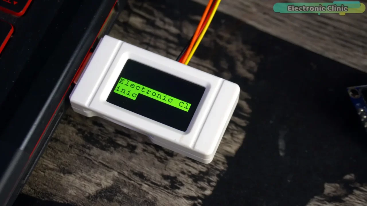
You can clearly see the Electronic Clinic text on the ESP32-S3 Geek’s display. It’s not necessary to just print simple text; you can also display sensor values!
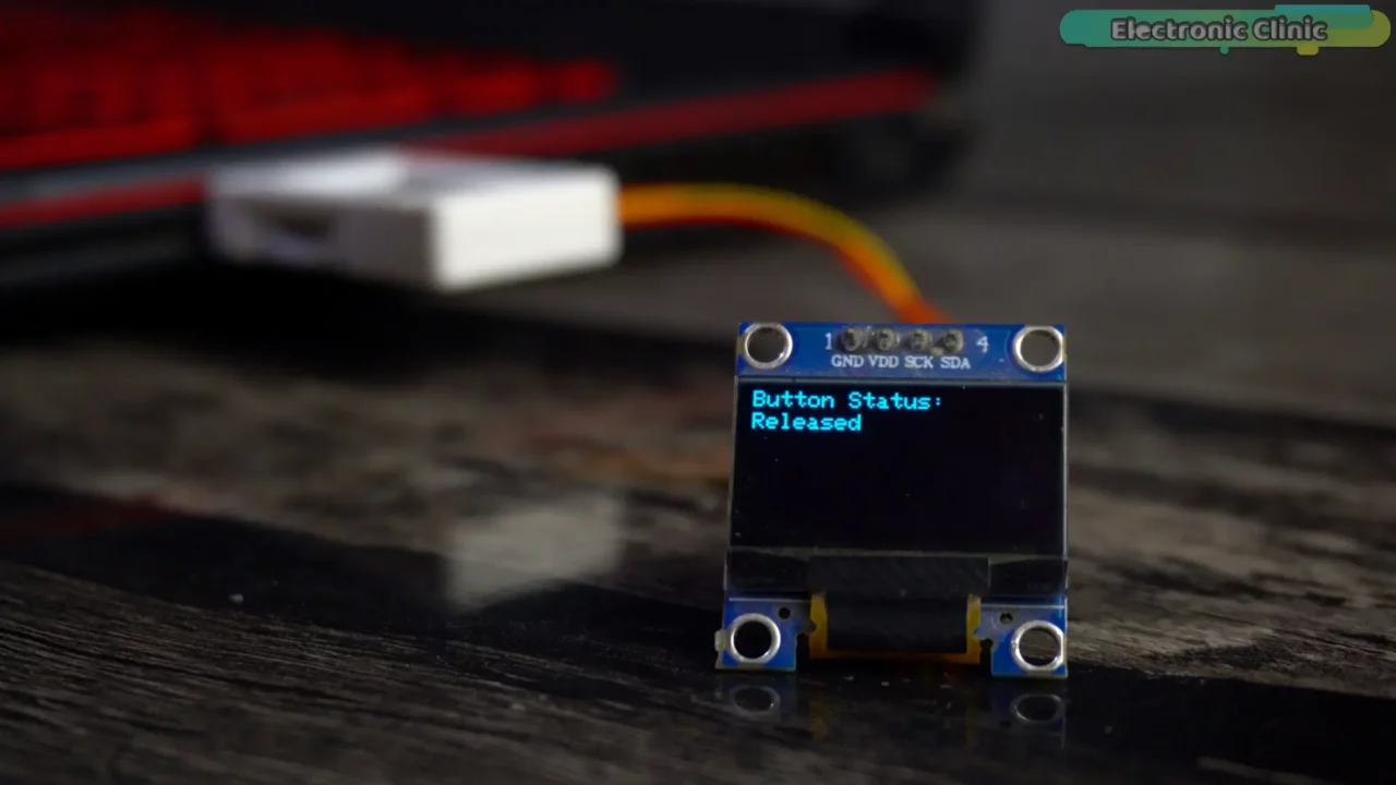
Anyway, Released means the BOOT button hasn’t been pressed. But if I press the BOOT button, its status will change from Released to Pressed.
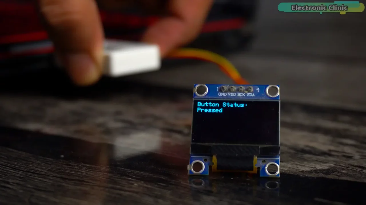
Isn’t that amazing?
Now, let’s move on to our 4th and final example, which is actually a practical project in itself!
ESP32-S3 Geek Example 4:
If you have already worked with ESP32, this project will feel like an intermediate level task. However, if it’s your first time using ESP32, it might feel a bit complex. But don’t worry, I will explain everything step by step.
For this project, you will also need one more ESP32 module. It can be any variant of the ESP32, such as the ESP32-S3, ESP32-C3, or even the simple ESP32 Dev Module like the one I am using.
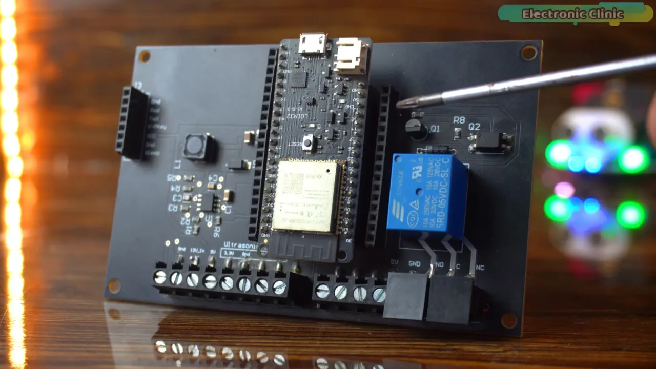
As usual, I will be using my designed ESP32 Development board, for which I have already made a video. However, if you prefer, you can also make the same connections on a breadboard. This development board already has a 5V SPDT relay and female headers, so I don’t need extra wiring. I just need to connect one sensor or multiple sensors to display their values on the ESP32-S3 Geek Development Board.
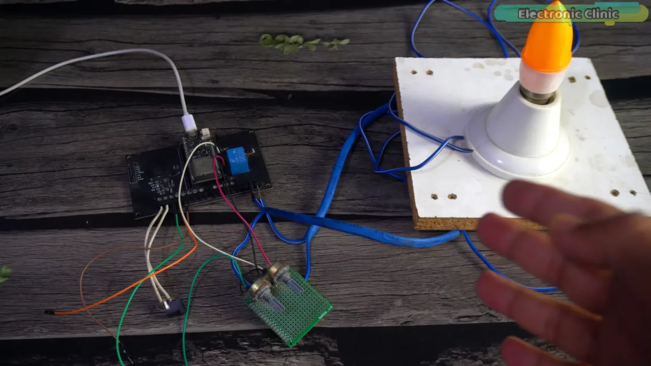
For the practical demonstration, I’ve also connected a 220V AC bulb to the relay, which we’ll control in just a few seconds.
Safety First!
Please, never touch the relay contacts when the 220V AC supply is connected. As a safety precaution, always wear protective gloves and conduct high-voltage experiments in the presence of someone knowledgeable about the safety rules and regulations.
As you can see, I have connected a potentiometer to the ESP32 Dev Module, which I will use as a sensor.
Interfacing:
The left and rightmost legs of the potentiometer are connected to 3.3V and GND, and the middle leg is connected to GPIO34.
The relay is connected to GPIO13. For the relay connections you can follow this circuit diagram.
On the ESP32-S3 Geek side, you don’t need to do anything except upload the program.
ESP32-S3 Geek Code:
|
1 2 3 4 5 6 7 8 9 10 11 12 13 14 15 16 17 18 19 20 21 22 23 24 25 26 27 28 29 30 31 32 33 34 35 36 37 38 39 40 41 42 43 44 45 46 47 48 49 50 51 52 53 54 55 56 57 58 59 60 61 62 63 64 65 66 67 68 69 70 71 72 73 74 75 76 77 78 79 80 81 82 83 84 85 86 87 88 89 90 91 92 93 94 95 96 97 98 99 100 101 102 103 104 105 106 107 108 109 110 111 112 113 114 115 116 117 118 119 120 121 122 123 124 125 126 127 128 129 130 131 132 133 134 135 136 137 138 139 140 141 142 143 144 145 146 147 148 149 150 151 152 153 154 155 156 157 158 159 160 161 162 163 164 165 166 167 168 169 170 171 172 173 174 175 176 177 178 179 180 181 182 183 184 185 186 187 188 189 190 191 192 193 194 195 196 197 198 199 200 201 202 203 204 205 206 207 208 209 210 211 212 213 214 215 216 217 218 219 220 221 222 223 224 225 226 227 228 229 230 231 232 233 234 235 236 237 238 239 240 241 242 243 244 245 246 247 248 249 250 251 252 253 254 255 256 257 258 259 260 261 262 263 264 265 266 267 268 269 270 271 272 273 274 275 276 277 278 279 280 281 282 283 284 285 286 287 288 289 290 291 292 293 294 295 296 297 298 299 300 301 302 303 304 305 306 307 308 309 310 311 312 313 314 315 316 317 318 319 320 321 322 323 324 325 326 327 328 329 330 331 332 333 334 335 336 337 338 339 340 341 342 343 344 345 346 347 348 349 350 351 352 353 354 355 356 357 358 359 360 361 362 363 364 365 366 367 368 369 370 371 372 373 374 375 376 377 378 379 380 381 382 383 384 385 386 387 388 389 |
/***************************************************************************** * | Project : Two way communication between ESP32S3-GEEK and ESP32 Dev Module * | Author : Engr. Shahzada Fahad | Website : https://www.electroniclinic.com/ * | Function : ESP32-S3 Geek controls ESP32 Relay module via mDNS/HTTP, * | displays relay status and potentiometer value. * | Info : Uses fixed-width clearing for LCD updates. Corrected color. *---------------- ******************************************************************************/ #include <WiFi.h> #include <ESPmDNS.h> #include <HTTPClient.h> // Use the standard HTTPClient library #include <SPI.h> // May be needed by the LCD library // Include the specific LCD and GUI libraries for the ESP32-S3-GEEK display #include "LCD_Driver.h" #include "GUI_Paint.h" #include "fonts.h" // --- WiFi Settings --- // ***** REPLACE WITH YOUR ACTUAL WIFI CREDENTIALS ***** #define WIFI_SSID "fahad" #define WIFI_PASSWORD "fahad123" // --- mDNS Settings --- #define MDNS_SERVICE_TYPE "_relaycontrol" #define MDNS_SERVICE_PROTOCOL "_tcp" // --- State Variables --- IPAddress relayServerIP; int relayServerPort = 0; bool relayServerFound = false; unsigned long lastDiscoveryAttempt = 0; const long discoveryInterval = 5000; // --- Button Definition --- #define BUTTON_PIN 0 int currentButtonState = HIGH; int lastReadingButtonState = HIGH; unsigned long lastDebounceTime = 0; unsigned long debounceDelay = 50; int desiredRelayState = 0; // Tracks the state we *want* to send // --- Relay Status --- volatile int currentRelayState = -1; // Tracks the *confirmed* or last known state (-1: Unknown, 0: OFF, 1: ON) volatile bool newRelayStatusData = false; // Flag to update LCD with relay status // --- Potentiometer Data --- unsigned long lastPotRequestTime = 0; const long potRequestInterval = 1000; volatile int receivedPotValue = -1; volatile bool newPotData = false; // --- LCD --- #define LCD_DISPLAY_FONT &Font24 const int LCD_FONT_HEIGHT = 24; // Approx height for Font24 // --- Setup --- void setup() { Serial.begin(115200); Serial.println("\n\n--- Geek Module (mDNS Client + HTTP Client + Relay Status + Pot Display V1.3) ---"); // Initialize Button pinMode(BUTTON_PIN, INPUT_PULLUP); lastReadingButtonState = digitalRead(BUTTON_PIN); currentButtonState = lastReadingButtonState; Serial.print("Button Pin: "); Serial.println(BUTTON_PIN); // Initialize desired state based on assumption relay starts OFF desiredRelayState = 0; // Assume OFF initially currentRelayState = -1; // Unknown until first confirmation or action // Initialize LCD Serial.print("Initializing LCD..."); Config_Init(); LCD_Init(); LCD_SetBacklight(100); Paint_NewImage(LCD_WIDTH, LCD_HEIGHT, 90, WHITE); Paint_SetRotate(90); LCD_Clear(BLACK); Paint_Clear(BLACK); Serial.println(" Done."); Paint_DrawString_EN(10, 10, "Initializing...", LCD_DISPLAY_FONT, WHITE, BLACK); // Initialize WiFi Serial.print("Connecting to WiFi: "); Serial.println(WIFI_SSID); WiFi.mode(WIFI_STA); WiFi.begin(WIFI_SSID, WIFI_PASSWORD); unsigned long startAttemptTime = millis(); while (WiFi.status() != WL_CONNECTED && millis() - startAttemptTime < 15000) { Serial.print("."); delay(500); } if (WiFi.status() == WL_CONNECTED) { Serial.println("\nWiFi Connected!"); Serial.print("IP Address: "); Serial.println(WiFi.localIP()); Paint_DrawString_EN(10, 40, "WiFi OK", LCD_DISPLAY_FONT, GREEN, BLACK); } else { Serial.println("\nWiFi Connection Failed! Halting."); Paint_DrawString_EN(10, 40, "WiFi FAIL", LCD_DISPLAY_FONT, RED, BLACK); while (1) { delay(1000); } } // Initialize mDNS if (!MDNS.begin("geek-module-s3")) { Serial.println("Error setting up MDNS responder!"); } Serial.println("mDNS Started. Ready to query."); Paint_DrawString_EN(10, 70, "Searching...", LCD_DISPLAY_FONT, YELLOW, BLACK); Serial.println("Setup Complete. Searching for Relay Server..."); lastDiscoveryAttempt = millis() - discoveryInterval; } // --- Function to Discover Relay Server --- void discoverRelayServer() { Serial.print("Querying for mDNS service: "); Serial.print(MDNS_SERVICE_TYPE); Serial.print("."); Serial.println(MDNS_SERVICE_PROTOCOL); int n = MDNS.queryService(MDNS_SERVICE_TYPE, MDNS_SERVICE_PROTOCOL); if (n == 0) { Serial.println("No services found."); if (relayServerFound) { // If it was previously found, mark as lost Paint_Clear(BLACK); Paint_DrawString_EN(10, 10, "Relay Lost!", LCD_DISPLAY_FONT, RED, BLACK); Paint_DrawString_EN(10, 40, "Searching...", LCD_DISPLAY_FONT, YELLOW, BLACK); currentRelayState = -1; // State becomes unknown newRelayStatusData = true; // Trigger redraw to ??? receivedPotValue = -1; // Pot value also unknown now newPotData = true; // Trigger redraw Pot to --- } relayServerFound = false; } else { Serial.print(n); Serial.println(" service(s) found:"); bool foundOurService = false; for (int i = 0; i < n; ++i) { String serviceHostname = MDNS.hostname(i); IPAddress serviceIP = MDNS.queryHost(serviceHostname); uint16_t servicePort = MDNS.port(i); Serial.print(" "); Serial.print(i + 1); Serial.print(": "); Serial.print(serviceHostname); Serial.print(" Port: "); Serial.print(servicePort); if (serviceIP != IPAddress(0,0,0,0)) { Serial.print(" Resolved IP: "); Serial.println(serviceIP); relayServerIP = serviceIP; relayServerPort = servicePort; relayServerFound = true; foundOurService = true; Serial.print(">>> Found Relay Server at: "); Serial.print(relayServerIP); Serial.print(":"); Serial.println(relayServerPort); Paint_Clear(BLACK); // Clear entire screen on successful discovery Paint_DrawString_EN(10, 10, "Relay Found!", LCD_DISPLAY_FONT, CYAN, BLACK); Paint_DrawString_EN(10, 40, relayServerIP.toString().c_str(), LCD_DISPLAY_FONT, CYAN, BLACK); // Reset data flags and state on successful discovery currentRelayState = -1; // State unknown until first command/response newRelayStatusData = true; // Trigger status draw (will show ??? initially) receivedPotValue = -1; // Pot value unknown until first request newPotData = true; // Trigger pot draw (will show --- initially) break; // Stop searching once found } else { Serial.println(" Failed to resolve hostname to IP."); } } if (!foundOurService) { // Service type found, but IP resolution failed for all instances Serial.println("Service type found, but failed to resolve IP."); if (relayServerFound) { // If it was previously found, mark as lost/error Paint_Clear(BLACK); Paint_DrawString_EN(10, 10, "Resolve Err", LCD_DISPLAY_FONT, RED, BLACK); Paint_DrawString_EN(10, 40, "Searching...", LCD_DISPLAY_FONT, YELLOW, BLACK); currentRelayState = -1; newRelayStatusData = true; // Trigger redraw to ??? receivedPotValue = -1; newPotData = true; // Trigger redraw Pot to --- relayServerFound = false; // Mark as not found until successful resolution } else { // Still searching initially // Don't clear the whole screen, just update the searching line if needed // Paint_DrawString_EN(10, 70, "Searching...", LCD_DISPLAY_FONT, YELLOW, BLACK); } } } } // --- Function to Send Relay Command via HTTP --- void sendRelayCommand(int state) { if (!relayServerFound || WiFi.status() != WL_CONNECTED) { Serial.println("Cannot send command: Server not found or WiFi disconnected."); currentRelayState = -1; // Set state to unknown on failure newRelayStatusData = true; return; } WiFiClient client; HTTPClient http; String url = "http://" + relayServerIP.toString() + ":" + String(relayServerPort) + "/relay?state=" + String(state); Serial.print("Sending Command Request: "); Serial.println(url); if (http.begin(client, url)) { http.setConnectTimeout(2000); http.setTimeout(3000); int httpCode = http.GET(); if (httpCode == HTTP_CODE_OK) { String payload = http.getString(); Serial.print("Relay Command Response (State): "); Serial.println(payload); // Update relay state based on server response if (payload == "1") { currentRelayState = 1; // Confirmed ON } else if (payload == "0") { currentRelayState = 0; // Confirmed OFF } else { Serial.println("Received invalid state response from relay."); currentRelayState = -1; // Set state to unknown } } else { Serial.printf("Relay Command HTTP GET failed, code: %d\n", httpCode); currentRelayState = -1; // Set state to unknown on error } http.end(); } else { Serial.println("Relay Command HTTP Client failed to begin."); currentRelayState = -1; // Set state to unknown on error } newRelayStatusData = true; // Flag for LCD update regardless of success/failure of the command itself } // --- Function to Request Potentiometer Value --- void requestPotValue() { if (!relayServerFound || WiFi.status() != WL_CONNECTED) { // Don't attempt if server/wifi not available if (receivedPotValue != -1) { // If we previously had a value, mark it as stale/unknown receivedPotValue = -1; newPotData = true; // Trigger redraw to show --- } return; } WiFiClient client; HTTPClient http; String url = "http://" + relayServerIP.toString() + ":" + String(relayServerPort) + "/potvalue"; if (http.begin(client, url)) { http.setConnectTimeout(1500); http.setTimeout(2000); int httpCode = http.GET(); if (httpCode == HTTP_CODE_OK) { String payload = http.getString(); bool isNumeric = true; if (payload.length() == 0) isNumeric = false; // Handle empty response for (char c : payload) { if (!isDigit(c)) { isNumeric = false; break; } } if (isNumeric) { receivedPotValue = payload.toInt(); } else { Serial.print("Received non-numeric pot value: "); Serial.println(payload); receivedPotValue = -99; // Indicate data error } } else { Serial.printf("Pot Value HTTP GET failed, code: %d\n", httpCode); receivedPotValue = -httpCode; // Indicate HTTP error } http.end(); } else { Serial.println("Pot Value HTTP Client failed to begin."); receivedPotValue = -998; // Indicate client setup error } newPotData = true; // Flag for LCD update regardless of success/failure } // --- Loop --- void loop() { // mDNS Discovery if (!relayServerFound && millis() - lastDiscoveryAttempt > discoveryInterval) { discoverRelayServer(); lastDiscoveryAttempt = millis(); } // Potentiometer Value Request Timer if (relayServerFound && WiFi.status() == WL_CONNECTED && millis() - lastPotRequestTime > potRequestInterval) { requestPotValue(); lastPotRequestTime = millis(); } // Button Handling (Toggle Logic) int reading = digitalRead(BUTTON_PIN); if (reading != lastReadingButtonState) { lastDebounceTime = millis(); } if ((millis() - lastDebounceTime) > debounceDelay) { if (reading != currentButtonState) { currentButtonState = reading; if (currentButtonState == LOW) { // Pressed Serial.println("Button Pressed."); desiredRelayState = !desiredRelayState; // Toggle desired state Serial.print("Toggling Relay -> Sending Command State: "); Serial.println(desiredRelayState); sendRelayCommand(desiredRelayState); // Send command // currentRelayState is updated based on the *response* in sendRelayCommand } else { // Released Serial.println("Button Released."); } } } lastReadingButtonState = reading; // --- LCD Update --- bool needsUpdate = newRelayStatusData || newPotData; // Check flags // --- Define Fixed Clearing Widths (Adjust if necessary based on font/max text) --- const int relayStatusClearWidth = 200; // Generous width for "Relay: OFF", "Relay: ???", etc. const int potValueClearWidth = 200; // Generous width for "Pot: 4095" or error messages if (needsUpdate && relayServerFound) { // --- Update Relay Status --- if (newRelayStatusData) { char statusText[20]; UWORD statusColor = WHITE; // Default color if (currentRelayState == 1) { sprintf(statusText, "Relay: ON"); statusColor = GREEN; } else if (currentRelayState == 0) { sprintf(statusText, "Relay: OFF"); statusColor = RED; } else { // State is -1 (Unknown) or other error sprintf(statusText, "Relay: ???"); statusColor = YELLOW; // Use yellow for unknown/error } int textX = 10; // Position for relay status int textY = 75; // Clear a fixed, wider area Paint_ClearWindows(textX - 2, textY - 2, textX + relayStatusClearWidth, textY + LCD_FONT_HEIGHT + 2, BLACK); // Draw the status text Paint_DrawString_EN(textX, textY, statusText, LCD_DISPLAY_FONT, statusColor, BLACK); newRelayStatusData = false; // Reset the flag } // --- Update Potentiometer Value --- if (newPotData) { char potText[30]; UWORD potColor = YELLOW; // Default color for pot if (receivedPotValue < -900) { sprintf(potText, "Pot Conn Err"); potColor = RED;} // Connection error likely // --- CORRECTED COLOR HERE --- else if (receivedPotValue < 0) { sprintf(potText, "Pot Data Err"); potColor = MAGENTA;} // HTTP or Data error (Using MAGENTA) // ---------------------------- else { sprintf(potText, "Pot: %d", receivedPotValue); potColor = YELLOW; } // Normal value int textX = 10; // Position pot value below relay status int textY = 110; // Clear a fixed, wider area Paint_ClearWindows(textX - 2, textY - 2, textX + potValueClearWidth, textY + LCD_FONT_HEIGHT + 2, BLACK); // Draw the pot text Paint_DrawString_EN(textX, textY, potText, LCD_DISPLAY_FONT, potColor, BLACK); newPotData = false; // Reset the flag } } else if (!relayServerFound) { // When server is lost, check if screen needs updating due to state changes triggered during discovery loss if (newRelayStatusData || newPotData ) { // Check if flags were set during the disconnect process // Redisplay static "Lost" info and clear data areas // (Paint_Clear and top lines are handled in discoverRelayServer when loss is detected) // Ensure Relay status shows ??? int relayX = 10; int relayY = 75; Paint_ClearWindows(relayX - 2, relayY - 2, relayX + relayStatusClearWidth, relayY + LCD_FONT_HEIGHT + 2, BLACK); Paint_DrawString_EN(relayX, relayY, "Relay: ???", LCD_DISPLAY_FONT, YELLOW, BLACK); // Ensure Pot value shows --- int potX = 10; int potY = 110; Paint_ClearWindows(potX - 2, potY - 2, potX + potValueClearWidth, potY + LCD_FONT_HEIGHT + 2, BLACK); Paint_DrawString_EN(potX, potY, "Pot: ---", LCD_DISPLAY_FONT, YELLOW, BLACK); // Reset flags after drawing the 'lost' state newRelayStatusData = false; newPotData = false; } // No dynamic updates needed while lost, just the static 'Searching...' message area } delay(20); // Small delay for stability and background tasks } |
ESP32 Dev Module Code:
|
1 2 3 4 5 6 7 8 9 10 11 12 13 14 15 16 17 18 19 20 21 22 23 24 25 26 27 28 29 30 31 32 33 34 35 36 37 38 39 40 41 42 43 44 45 46 47 48 49 50 51 52 53 54 55 56 57 58 59 60 61 62 63 64 65 66 67 68 69 70 71 72 73 74 75 76 77 78 79 80 81 82 83 84 85 86 87 88 89 90 91 92 93 94 95 96 97 98 99 100 101 102 103 104 105 106 107 108 109 110 111 112 113 114 115 116 117 118 119 120 121 122 123 124 125 126 127 128 129 130 131 132 133 134 135 136 137 138 139 140 141 142 143 144 145 146 147 148 149 150 151 152 153 154 155 156 157 158 159 160 161 162 163 164 165 166 167 168 169 170 171 172 173 174 |
// Relay_Module_mDNS_Server_With_Pot_NoCounter.ino #include <WiFi.h> #include <ESPmDNS.h> #include <WebServer.h> // Use the standard WebServer library #include <driver/adc.h> // Required for adc1_config_width and adc1_config_channel_atten // --- Relay Definition --- #define RELAY_PIN 13 // Make sure this matches your board's connection // --- Potentiometer Definition --- #define POT_PIN 34 // ADC1_CH6 on most ESP32 Dev Modules // --- WiFi Settings --- // ***** REPLACE WITH YOUR ACTUAL WIFI CREDENTIALS ***** #define WIFI_SSID "fahad" #define WIFI_PASSWORD "fahad123" // --- mDNS Settings --- #define MDNS_HOSTNAME "relay-module" // Name device will respond to (e.g., http://relay-module.local) #define MDNS_SERVICE_TYPE "_relaycontrol" // Custom service type (starts with underscore) #define MDNS_SERVICE_PROTOCOL "_tcp" // Protocol #define WEB_SERVER_PORT 80 // Port for HTTP communication // --- Web Server --- WebServer server(WEB_SERVER_PORT); // --- State Variables --- // int actionCounter = 0; // REMOVED COUNTER int currentPotValue = 0; // Variable to store the latest potentiometer reading // --- Function Prototypes --- void handleRelayControl(); void handlePotValue(); void handleNotFound(); void handleRoot(); // --- Setup --- void setup() { Serial.begin(115200); Serial.println("\n\n--- Relay Module (mDNS Server + Web Server + Pot - No Counter) ---"); // --- Initialize Relay --- pinMode(RELAY_PIN, OUTPUT); digitalWrite(RELAY_PIN, HIGH); // Initialize relay OFF (Active LOW assumed) Serial.print("Relay Pin: "); Serial.println(RELAY_PIN); // --- Initialize Potentiometer ADC --- Serial.print("Initializing Potentiometer on Pin: "); Serial.println(POT_PIN); adc1_config_width(ADC_WIDTH_BIT_12); adc1_config_channel_atten(ADC1_CHANNEL_6, ADC_ATTEN_DB_11); Serial.println("ADC Configured for Potentiometer."); // --- Initialize WiFi --- Serial.print("Connecting to WiFi: "); Serial.println(WIFI_SSID); WiFi.mode(WIFI_STA); WiFi.begin(WIFI_SSID, WIFI_PASSWORD); unsigned long startAttemptTime = millis(); while (WiFi.status() != WL_CONNECTED && millis() - startAttemptTime < 15000) { Serial.print("."); delay(500); } if (WiFi.status() == WL_CONNECTED) { Serial.println("\nWiFi Connected!"); Serial.print("IP Address: "); Serial.println(WiFi.localIP()); } else { Serial.println("\nWiFi Connection Failed! Halting."); while (1) { delay(1000); } } // --- Initialize mDNS --- Serial.print("Starting mDNS responder with hostname '"); Serial.print(MDNS_HOSTNAME); Serial.println("'"); if (!MDNS.begin(MDNS_HOSTNAME)) { Serial.println("Error setting up MDNS responder!"); while (1) { delay(1000); } } Serial.println("mDNS responder started."); MDNS.addService(MDNS_SERVICE_TYPE, MDNS_SERVICE_PROTOCOL, WEB_SERVER_PORT); Serial.print("Advertised Service Type: "); Serial.println(MDNS_SERVICE_TYPE); Serial.print("Protocol: "); Serial.println(MDNS_SERVICE_PROTOCOL); Serial.print("Port: "); Serial.println(WEB_SERVER_PORT); // --- Setup Web Server Handlers --- server.on("/", HTTP_GET, handleRoot); server.on("/relay", HTTP_GET, handleRelayControl); server.on("/potvalue", HTTP_GET, handlePotValue); server.onNotFound(handleNotFound); server.begin(); Serial.println("HTTP server started."); Serial.println("Setup Complete. Waiting for client requests..."); } // --- Loop --- void loop() { // Read Potentiometer Value currentPotValue = adc1_get_raw(ADC1_CHANNEL_6); Serial.println(currentPotValue); // Handle incoming client requests server.handleClient(); delay(10); } // --- Web Server Handler Functions --- // Handle requests to /relay?state=X void handleRelayControl() { Serial.print("Received /relay request from client: "); Serial.println(server.client().remoteIP()); String stateStr = server.arg("state"); int relayState = -1; if (stateStr.length() > 0) { relayState = stateStr.toInt(); } if (relayState == 1) { // Turn ON Serial.println("Command: Relay ON (Pin LOW)"); digitalWrite(RELAY_PIN, LOW); // actionCounter++; // REMOVED COUNTER // Serial.print("Counter incremented: "); Serial.println(actionCounter); // REMOVED COUNTER server.send(200, "text/plain", "1"); // Respond with current state (ON) } else if (relayState == 0) { // Turn OFF Serial.println("Command: Relay OFF (Pin HIGH)"); digitalWrite(RELAY_PIN, HIGH); // actionCounter++; // REMOVED COUNTER // Serial.print("Counter incremented: "); Serial.println(actionCounter); // REMOVED COUNTER server.send(200, "text/plain", "0"); // Respond with current state (OFF) } else { Serial.println("Invalid or missing 'state' parameter."); server.send(400, "text/plain", "Bad Request: Invalid or missing 'state' parameter (use state=0 or state=1)"); // No valid state change, so don't send 0 or 1 } } // Handle requests to /potvalue void handlePotValue() { Serial.print("Received /potvalue request from client: "); Serial.println(server.client().remoteIP()); server.send(200, "text/plain", String(currentPotValue)); } // Handle requests to the root path "/" void handleRoot() { Serial.println("Received / request"); String html = "<!DOCTYPE html><html><head><title>Relay Control Status</title></head><body>"; html += "<h1>Relay Module Status</h1>"; // Read the *actual* current pin state to display bool isRelayOn = (digitalRead(RELAY_PIN) == LOW); // Assuming active LOW html += "<p>Current Relay State (Pin " + String(RELAY_PIN) + "): " + (isRelayOn ? "ON" : "OFF") + "</p>"; // html += "<p>Action Counter: " + String(actionCounter) + "</p>"; // REMOVED COUNTER html += "<p>Current Potentiometer Value: " + String(currentPotValue) + " (0-4095)</p>"; html += "<p>Send GET request to /relay?state=1 (ON) or /relay?state=0 (OFF)</p>"; html += "<p>Send GET request to /potvalue to get potentiometer reading</p>"; html += "</body></html>"; server.send(200, "text/html", html); } // Handle requests to routes that haven't been defined void handleNotFound() { String message = "File Not Found\n\n"; message += "URI: "; message += server.uri(); message += "\nMethod: "; message += (server.method() == HTTP_GET) ? "GET" : "POST"; message += "\nArguments: "; message += server.args(); message += "\n"; for (uint8_t i = 0; i < server.args(); i++) { message += " " + server.argName(i) + ": " + server.arg(i) + "\n"; } Serial.print("Responding 404 for: "); Serial.println(server.uri()); server.send(404, "text/plain", message); } |
Practical Demonstration:
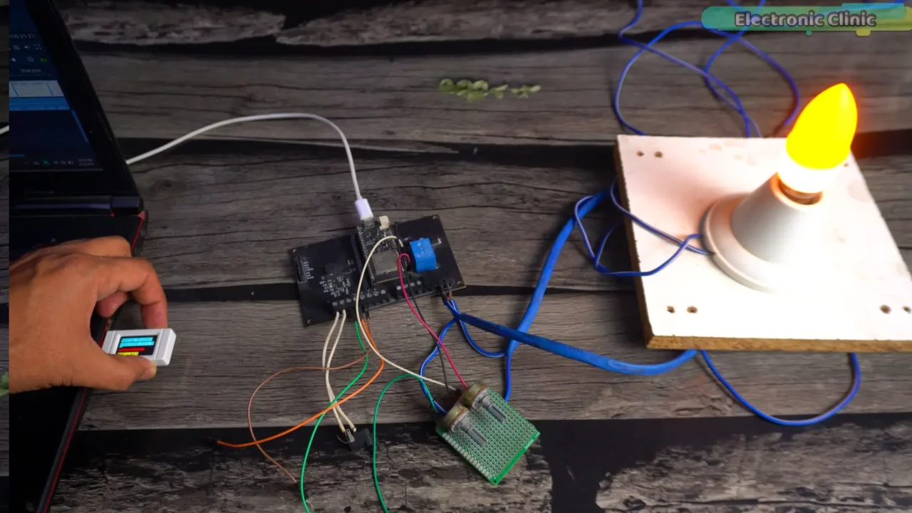
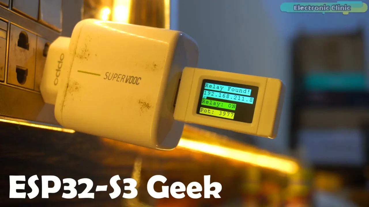
Both development boards are connected to WiFi networks. Now, let’s control the 220Vac light using the ESP32-S3 Geek Development board.
Simply hold the BOOT button for a short duration to turn the light ON and OFF.
You can replace this light with any load you wish. And if you want to control high-ampere loads, just increase the relay size.
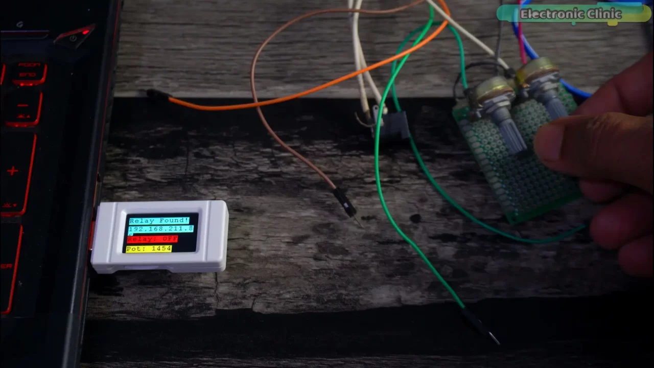
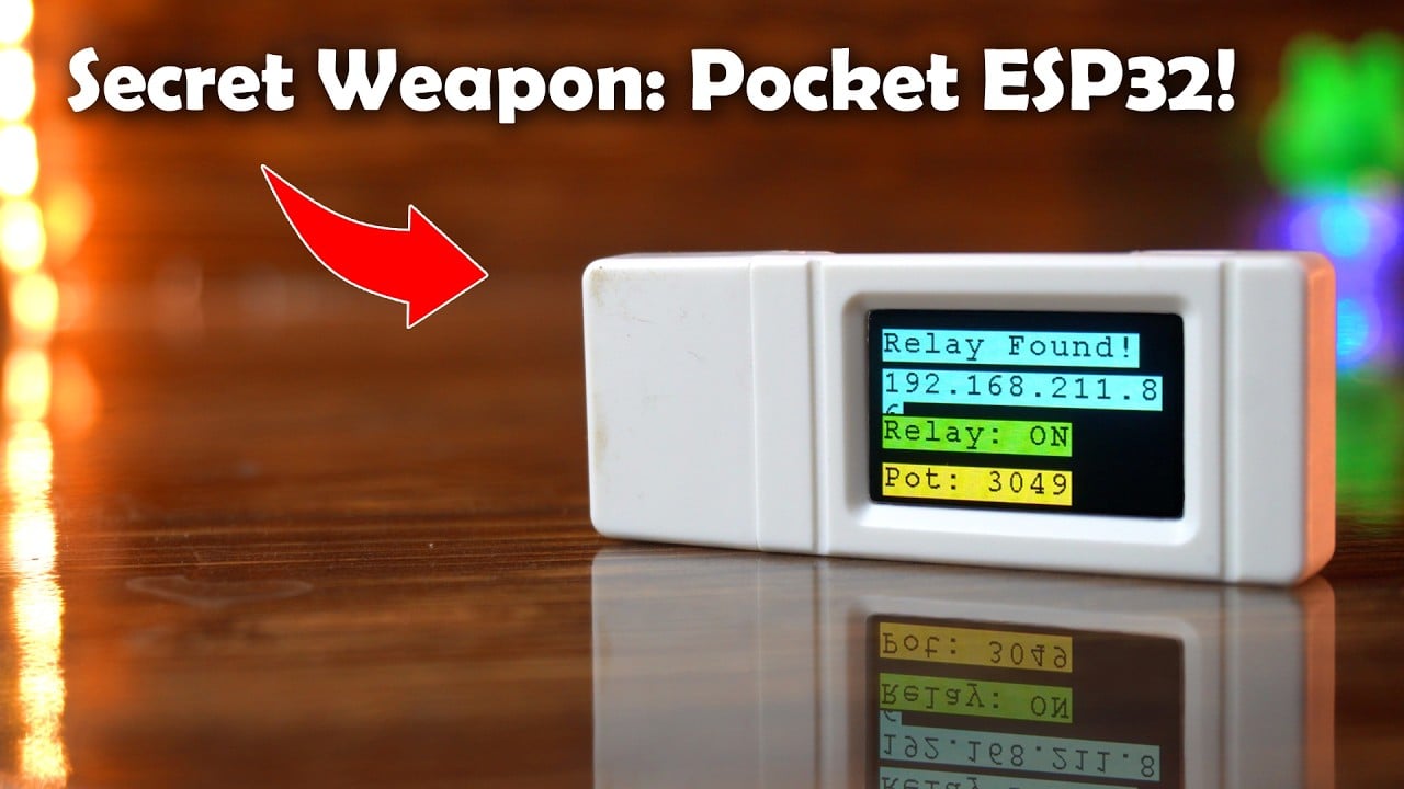
Now, as I started to rotate the knob of the Potentiometer, the value on the ESP32-S3 Geek’s display started to increase.
I have used the potentiometer because it’s easily available everywhere. However, you can use any other sensor if you prefer.
This is a complete two-way communication system; we are sending commands from the ESP32-S3 Geek Development Board to control the relay while simultaneously monitoring the potentiometer’s value.
It’s not just limited to being used with a laptop; you can also use it with a cell phone charger.
Honestly, the ESP32-S3 Geek Development Board has truly impressed me, and I am planning to use it in a high-level security project soon.
So, that’s all for now!
Support me on Patreon for more Articles and videos.
Watch Video Tutorial:
Discover more from Electronic Clinic
Subscribe to get the latest posts sent to your email.


