ESP32-S3 Touchscreen Display Project: You Won’t Believe What This Touchscreen Can Do!
Go beyond the basics and see what’s possible when you build a next-level ESP32-S3 Touchscreen Display Project
Last Updated on March 9, 2026 by Engr. Shahzada Fahad
Table of Contents
Description:
ESP32-S3 Touchscreen Display Project: You Won’t Believe What This Touchscreen Can Do! – Want to build stunning user interfaces on a massive 5-inch touchscreen… using just the ESP32? Imagine controlling smart home devices, building your own dashboard, or even making your own handheld gadget; all on this powerful display!

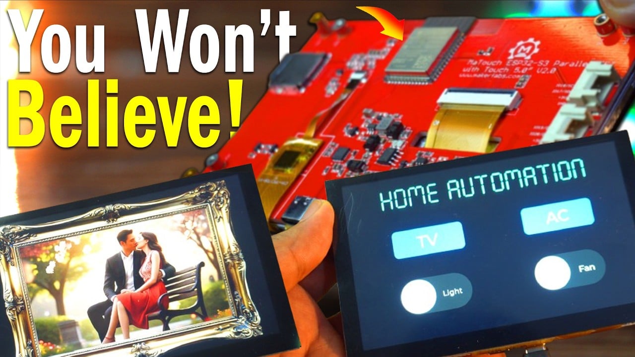
In this article, we are diving deep into the MaTouch ESP32-S3 Parallel TFT with Touch; a feature-packed development board that combines a vibrant 5-inch IPS screen with the speed and power of the ESP32-S3. If you have been thinking about building your next touchscreen project, this might be the perfect tool for you.
We will start by exploring the complete specs of this board in simple terms. Then, I will show you which Arduino libraries you need and how to install them step by step. After that, we will jump into SquareLine Studio to design a basic user interface; and finally, we will bring it all to life using LVGL on the Arduino side.
So, let’s begin with a closer look at the hardware and what makes this display such a powerful platform for your next embedded UI project.
Specifications:

This is the MaTouch ESP32-S3 Parallel TFT with Touch – a powerful development board with a large 5-inch IPS display. It has a high resolution of 800×480 pixels and supports 5-point capacitive touch using the GT911 touch driver. At the heart of this board is the ESP32-S3-WROOM-1 module with a built-in PCB antenna, 16MB flash, and 8MB PSRAM. It supports both WiFi and Bluetooth 5.0, making it great for wireless projects. The display uses a 24-bit RGB interface for rich colors. For connectivity, it offers two USB Type-C ports – one for USB-to-UART using the CP2104 chip, and one for native USB. It also includes a reset button, a flash button, and Mabee interfaces for I2C and GPIO. You can add a microSD card, and yes, it fully supports the Arduino platform. It runs on 5V through USB-C, it works perfectly within a voltage range of 4.0 to 5.25 volts. It’s reliable even in extreme temperatures, from -40°C to +85°C.
- Controller: ESP32-S3-WROOM-1, PCB Antenna, 16MB Flash, 8MB PSRAM, ESP32-S3-WROOM-1-N16R8
- Wireless: Wifi& Bluetooth 5.0
- LCD: 5 inch High Lightness IPS
- Resolution: 800*480
- LCD interface: RGB 24bit
- Touch Panel: 5 Points Touch, Capacitive
- Touch Panel Driver: GT911
- USB: Dual USB Type-C(one for USB-to-UART and one for native USB)
- USB to UART Chip: CP2104
- Power Supply: USB Type-C 5.0V(4.0V~5.25V)
- Button: Flash button and reset button
- Mabee interface: 1I2C;1GPIO
- MicroSD: Yes
- Arduino support: yes
- Type-C Power Delivery: Not Supported
- Operation temperature: -40℃ to +85℃
Now that we have covered the hardware, let’s talk about the software setup; because without the right versions, things might not work properly.
Arduino IDE Version:
Although Makerfabs has tested this display with both Arduino IDE versions 1.8.19 and 2.3.4, I am using Arduino IDE version 2.3.4 in this video, and everything works perfectly.
ESP32 Version:
For the ESP32 board package, make sure you install ESP32 version 2.0.11. This specific version is important for compatibility, especially with the display and touch libraries.
Library Versions:
Now let’s go over the libraries you will need:
- Arduino_GFX Library by Moon On Our Nation – version 1.3.1
- JPEGDEC by Larry Bank – version 1.2.7
- And for the touch interface, you will need the TAMC_GT911 library – version 1.0.2 by TAMC.
Once you have these installed, you are all set to start coding. But before we jump into code, let’s create a basic UI using SquareLine Studio.

I have already created a template folder for you, and inside this folder, I have added all the required files to save you time. I have also included two extra folders; one where you can save your SquareLine Studio project files, and another one where you can save the generated UI files.
Now, the .h and .c files you see along with the Arduino sketch; these are the UI files generated by SquareLine Studio. I have already explained all of this in detail in my previous videos and articles.
In fact, I have a complete series on SquareLine Studio and LVGL. So, if this is your first time using them, I highly recommend watching those videos first on my YouTube channel “Electronic Clinic”.
Anyway, let’s go ahead and import this project into SquareLine Studio.

On the screen, you can see I have just written ‘Electronic Clinic’. As I always say; before you start any project, make sure to test it first. Once everything is working, then you can go ahead and design your own UI.
So first, let’s test this setup; and once that’s done, we will start modifying it.
So, let’s go ahead and export the UI files.
After exporting the UI files.
Next, go to the UI files folder… copy all the generated files… and paste them into the same folder where your Arduino.ino file is located.
Finally, you can go ahead and open the Arduino .ino file.
ESP32-S3 Touchscreen Display Project Code:
|
1 2 3 4 5 6 7 8 9 10 11 12 13 14 15 16 17 18 19 20 21 22 23 24 25 26 27 28 29 30 31 32 33 34 35 36 37 38 39 40 41 42 43 44 45 46 47 48 49 50 51 52 53 54 55 56 57 58 59 60 61 62 63 64 65 66 67 68 69 70 71 72 73 74 75 76 77 78 79 80 81 82 83 84 85 86 87 88 89 90 91 92 93 94 95 96 97 98 99 100 101 102 103 104 105 106 107 108 109 110 111 112 113 114 115 116 117 118 119 120 121 122 123 124 125 126 127 128 129 130 131 132 133 134 135 136 137 138 139 140 141 142 143 144 145 146 147 148 149 |
/* Arduino IDE 2.3.4 ESP32 Board v2.0.11 Arduino_GFX_Library for Arduino v1.3.1 JPEGDEC v1.2.7 TAMC_GT911 v1.0.2 Tools: PSRAM:"OPI PSRAM" */ #include <lvgl.h> #include <Arduino_GFX_Library.h> #include "touch.h" #include "ui.h" #define GFX_BL 10 /*Change to your screen resolution*/ static const uint16_t screenWidth = 800; static const uint16_t screenHeight = 480; static lv_disp_draw_buf_t draw_buf; static lv_color_t buf[ screenWidth * screenHeight / 10 ]; Arduino_ESP32RGBPanel *bus = new Arduino_ESP32RGBPanel( GFX_NOT_DEFINED /* CS */, GFX_NOT_DEFINED /* SCK */, GFX_NOT_DEFINED /* SDA */, 40 /* DE */, 41 /* VSYNC */, 39 /* HSYNC */, 42 /* PCLK */, 45 /* R0 */, 48 /* R1 */, 47 /* R2 */, 21 /* R3 */, 14 /* R4 */, 5 /* G0 */, 6 /* G1 */, 7 /* G2 */, 15 /* G3 */, 16 /* G4 */, 4 /* G5 */, 8 /* B0 */, 3 /* B1 */, 46 /* B2 */, 9 /* B3 */, 1 /* B4 */ ); Arduino_RPi_DPI_RGBPanel *gfx = new Arduino_RPi_DPI_RGBPanel( bus, 800 /* width */, 0 /* hsync_polarity */, 8 /* hsync_front_porch */, 4 /* hsync_pulse_width */, 8 /* hsync_back_porch */, 480 /* height */, 0 /* vsync_polarity */, 8 /* vsync_front_porch */, 4 /* vsync_pulse_width */, 8 /* vsync_back_porch */, 1 /* pclk_active_neg */, 16000000 /* prefer_speed */, true /* auto_flush */); #if LV_USE_LOG != 0 /* Serial debugging */ void my_print(const char * buf) { Serial.printf(buf); Serial.flush(); } #endif /* Display flushing */ void my_disp_flush( lv_disp_drv_t *disp, const lv_area_t *area, lv_color_t *color_p ) { uint32_t w = (area->x2 - area->x1 + 1); uint32_t h = (area->y2 - area->y1 + 1); #if (LV_COLOR_16_SWAP != 0) gfx->draw16bitBeRGBBitmap( area->x1, area->y1, (uint16_t*) &color_p->full, w, h ); #else gfx->draw16bitRGBBitmap( area->x1, area->y1, (uint16_t*) &color_p->full, w, h ); #endif lv_disp_flush_ready(disp); } /*Read the touchpad*/ void my_touchpad_read( lv_indev_drv_t * indev_driver, lv_indev_data_t * data ) { ts.read(); if (ts.isTouched) { int16_t touchX = ts.points[0].x; int16_t touchY = ts.points[0].y; data->state = LV_INDEV_STATE_PR; data->point.x = touchX; data->point.y = touchY; Serial.print("x="); Serial.println(touchX); Serial.print("y="); Serial.println(touchY); Serial.println(".........................."); } else { data->state = LV_INDEV_STATE_REL; } } void setup() { Serial.begin( 115200 ); /* prepare for possible serial debug */ String LVGL_Arduino = "Hello Arduino! "; LVGL_Arduino += String('V') + lv_version_major() + "." + lv_version_minor() + "." + lv_version_patch(); Serial.println( LVGL_Arduino ); Serial.println( "I am LVGL_Arduino" ); lv_init(); touch_init(); #if LV_USE_LOG != 0 lv_log_register_print_cb( my_print ); /* register print function for debugging */ #endif // Init Display gfx->begin(); gfx->fillScreen(BLACK); pinMode(GFX_BL, OUTPUT); digitalWrite(GFX_BL, LOW); lv_disp_draw_buf_init( &draw_buf, buf, NULL, screenWidth * screenHeight / 10 ); /*Initialize the display*/ static lv_disp_drv_t disp_drv; lv_disp_drv_init( &disp_drv ); /*Change the following line to your display resolution*/ disp_drv.hor_res = screenWidth; disp_drv.ver_res = screenHeight; disp_drv.flush_cb = my_disp_flush; disp_drv.draw_buf = &draw_buf; //disp_drv.sw_rotate = 1; // add for rotation //disp_drv.rotated = LV_DISP_ROT_90; // add for rotation lv_disp_drv_register( &disp_drv ); /*Initialize the (dummy) input device driver*/ static lv_indev_drv_t indev_drv; lv_indev_drv_init( &indev_drv ); indev_drv.type = LV_INDEV_TYPE_POINTER; indev_drv.read_cb = my_touchpad_read; lv_indev_drv_register( &indev_drv ); ui_init(); Serial.println( "Setup done" ); } void loop() { lv_timer_handler(); /* let the GUI do its work */ delay(5); } |
You don’t need to change anything in this code; all the required display and touch drivers are already included for you. Just connect your board, upload the code, and you are good to go!
Steps to Upload the Code:
To upload the code, go to the Tools menu, then navigate to Board > ESP32, and select ESP32S3 Dev Module.
Again go to the Tools Menu and select the communication port.
Again go to the Tools Menu then go to the Flash Size and select “16MB(128MB)”.
Then go to the Partition Scheme and select “16M Flash (3MB APP/9.9MB FATFS)”
Then go to the PSRAM and select OPI PSRAM.
And then finally, click on the upload button.

You can see how easily we have displayed the text on the screen. Once your display is working, the rest of the work becomes quite easy. Next, let’s add a custom font and display images on multiple screens.
Now let’s create a font. And just a quick reminder; in my previous article on the ESP32-S3 AMOLED Smartwatch UI, I have already explained how to create a custom font step by step and I have also explained how to use custom images. So if you haven’t read that yet, I highly recommend checking it out.

On Screen1, I used a custom font using Seven Segment. Then I added to more screens and added two images as the background.

First I tried adding 3 images, but it generated an error while uploading the code. So, I had to delete the 4th screen.

As you can see, creating custom fonts is super easy, and you can even build a photo album with it.

This is the image I added on the 2nd screen.

This is the image, I added on screen3. I was amazed at the quality. And let me tell you, that little model in the image is my Son “Fahaam Khan”.
These images you are seeing right now are stored directly on the ESP32, which means you can’t add too many due to limited space. That’s why I deleted screen3.
If you want to make a full digital album, you will need to store your images on an SD card instead.

Here are some sample images that I have saved on the SD card. Just download the code and upload it; that’s it. You can download all the codes, images, and other resources form my Patreon page.

Now, you can store as many images as you want in the SD Card.
And as you can see, our digital photo album is ready! Of course, the design is very basic right now; but if you are interested in advanced UI design, do check out my previous videos and articles.
So, that’s all for now.
Watch ESP32-S3 touchscreen project Video Tutorial:
Frequently Asked Questions (FAQ)
Q1: What software and libraries do I need for this ESP32-S3 touchscreen project?
For full compatibility, this project uses Arduino IDE v2.3.4, the ESP32 board package version 2.0.11, Arduino_GFX library v1.3.1, JPEGDEC library v1.2.7, and the TAMC_GT911 library v1.0.2 for the touch interface.
Q2: What is SquareLine Studio and why is it used in this project?
SquareLine Studio is a visual UI editor that allows you to design graphical user interfaces for embedded systems without writing complex code. We use it in this tutorial to easily design the layout, add fonts, and manage image assets for our ESP32-S3 display using the LVGL library.
Q3: Can the ESP32-S3 handle a large 800×480 touchscreen display?
Yes, absolutely. The ESP32-S3, especially the module used in the MaTouch display with 16MB Flash and 8MB PSRAM, is powerful enough to drive a high-resolution 800×480 display and render smooth graphics with the LVGL library.
Q4: Why did my project fail to upload after adding too many images?
This happens because the ESP32’s internal flash memory is limited. Storing large, high-resolution images directly in the project fills up this space quickly. For a project with many images, like a full digital photo album, you must store the images on an external SD card and load them from there.
Q5: How do I configure the Arduino IDE for the MaTouch ESP32-S3 display?
In the “Tools” menu, you must set the Board to “ESP32S3 Dev Module,” Flash Size to “16MB,” Partition Scheme to “16M Flash (3MB APP/9.9MB FATFS),” and enable PSRAM by selecting “OPI PSRAM.”
Discover more from Electronic Clinic
Subscribe to get the latest posts sent to your email.


HI Farhad
Intersting write up, enjoyed it. I have used similar display for my ecg project but with 4.3sunton display board and i find this board is similar to one you worked on but yours look bettr, i woul be glad to associate with you in the vital sign display projetc next in line.
Lets connect please?