LVGL ESP32 & SquareLine Tutorial using Arduino IDE
Last Updated on December 29, 2024 by Engr. Shahzada Fahad
Table of Contents
LVGL ESP32 & SquareLine:
LVGL ESP32 & SquareLine Tutorial using Arduino IDE- From today, I am starting a complete series on Smartwatch programming. Throughout this series, we will be using the CrowPanel ESP32-C3 1.28-inch IPS Capacitive Touch Display. I have already written a getting started tutorial on this display, so before reading this article, I highly recommend reading my previous article; you can also watch its video available on my YouTube Channel “Electronic Clinic”.
In that article, I talked in detail about its hardware, how to install the ESP32-C3 board in the Arduino IDE, which libraries you need to install, and at the end, I also shared 5 examples. These examples demonstrate how to control the Vibration Motor and Buzzer, check if a button is pressed, access the date and time from the RTC (Real-Time Clock/Calendar), and read the x, y values along with gestures.

In this first article, we are going to make this simple counter because I don’t want to make it complicated for you. For now, your only focus should be on how to create a simple graphical user interface “GUI” in SquareLine Studio and then generate UI Files to use them in the Arduino IDE with the LVGL library. It took me two days to figure out how to use SquareLine Studio and LVGL together. Anyway, after fixing all the errors, I finally made a basic template folder for myself. You can also download this template folder from my Patreon page, this will make your work a lot easier.
If you open the basic template folder, you will find the Arduino project folder “first_project”.

Inside this folder, you will find the Arduino “first_project.ino” file, it’s name should match the folder name. Along with the Arduino main file, you will also need to place these other files in the same project folder.
CST816D.cpp
CST816D.h
do_main.cpp
do_mian.h
I2C_BM8563.cpp
I2C_BM8563.h
Lv_confi.h
You can download these files from the ESP32_1.28_Arduino_Demo folder. This is the same folder we downloaded from the product’s official page, in the previous article. Open this folder, go to the libraries folder, and copy this file.

Then go to your Arduino project folder and paste it.
Next, go to the factory_demo folder, open the ESP_Watch_Demo folder and copy these files.
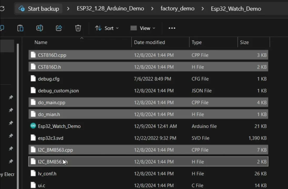
And paste them in your Arduino project folder as well.

Next, create two folders, in the “squareline project files” folder we will keep the SquareLine Project files and inside the “ui files” folder we will keep the UI files. Right now these folders are empty.
When your basic template folder is ready then you can go ahead and open the SquareLine Studio.
SquareLine Studio First Project:
I am using the SquareLine Studio 1.5.0.
Click the + Create button, select Arduino, and then click on the Arduino with TFT_eSPI.

On the Right side you can see the BOARD DESCRIPTION. TFT_eSPI supports Raspberry pi Pico, ESP32, ESP32-S2, ESP32-C3, ESP32-S3, and STM controllers.
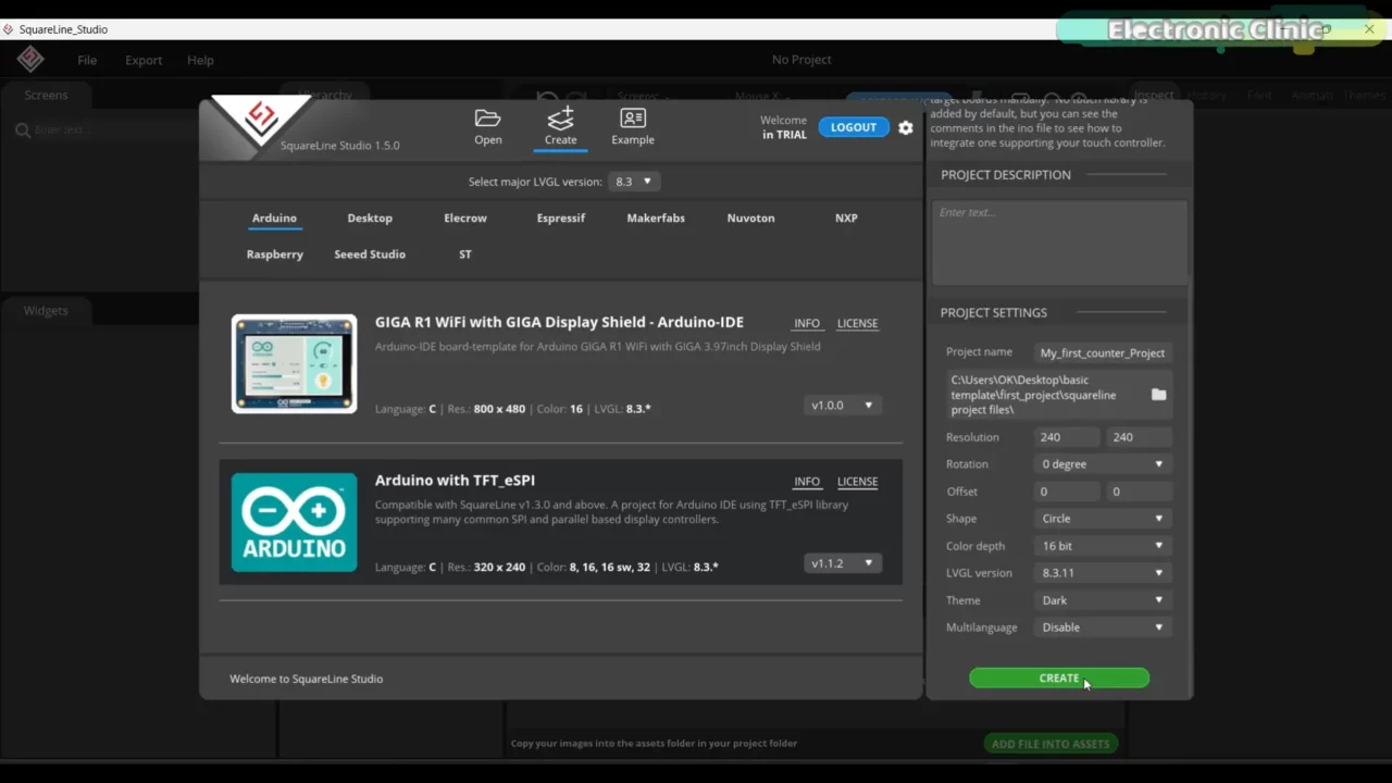
Under the project settings,
- you can set the project name. I named it my_first_counter_Project.
- Next, we have to select a folder, where we have to save the SquareLine project files. If you remember, we created a folder for this; inside the first_project folder with the name squareline project files. Simply select that folder.
- Next, we have to select the display resolution. The CrowPanel resolution is 240*240.
- We are going to leave Rotation to its default value, but if you want you can change it.
- Let’s also keep the Offset to its default values.
- Next, we have to select the display shape, the one I am using is round, so I am going to select Circle.
- Select the color depth as 16 bit.
- You can see the LVGL version 8.3.11. We will install the same version of the LVGL library in the Arduino IDE, otherwise it will generate an error.
- Next, you can select a Light or Dark theme as per your preference. But I am going to proceed with the Dark theme.
- Finally, you can enable or disable the Multilanguage support, but in my case I am going to leave it as it is.
So, that’s all about the project settings, finally you can go ahead and click the CREATE button.

By default, Screen1 will be added.
On the left side, you can see Screens, and on the Widgets tab, you can see the Basic Widgets, CONTROLLER, VISUALISER, and SCREEN.
On the right side, you can see the Inspector tab. When this tab is selected, we can configure the SCREEN settings, STYLE settings, and add Events.
On the History tab, we can go back in time.
On the Font tab, we can create our own custom fonts. This one is my favorite, and I will explain it in upcoming videos and articles.
On the Animation tab, you can create amazing, eye-catching animations. Finally, on the Themes tab, you can create themes. We will cover everything step by step; but in this article, we will only be using the Inspector tab.
Anyway, go to the File menu and click on Project Settings.

Double-check the properties.
Next, under FILE EXPORT, select the Project Export Root. We need to add a path to the folder we created in the basic template, simply select the squareline project files folder.
Next, we have to select a path for the UI Files Export Path. If you remember, we also created a folder for the UI Files.
For the LVGL include Path, we can simply type lvgl.h.
Finally, make sure to check the Flat Export (exports all files to one folder). Then, go ahead and click the APPLY CHANGES button.
Now, let’s go ahead and install the LVGL library in the Arduino IDE.
Arduino LVGL Library Installation:
Open the latest version of the Arduino IDE. First of all, make sure you have installed the ESP32 board and the basic libraries needed for the CrowPanel display. I have already explained this in my previous video.
Once you are done with that, click on the LIBRARY MANAGER and search for LVGL.
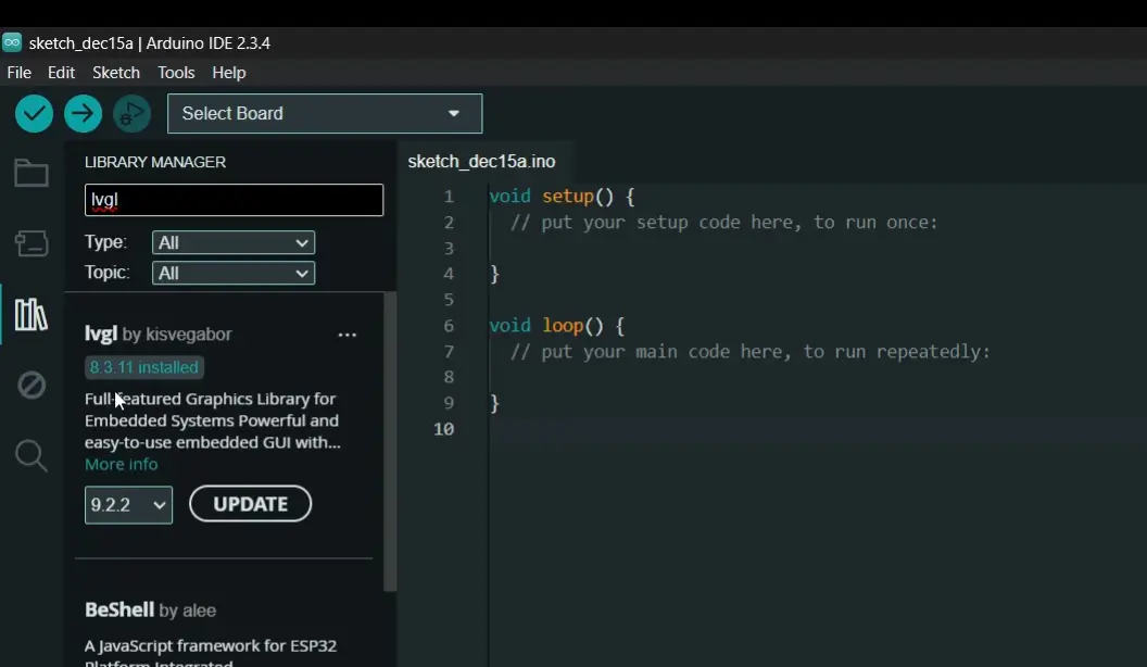
Make sure to install lvgl 8.3.11. This version of the LVGL library is fully compatible with the SquareLine Studio I am currently using.
Now, let’s go back to SquareLine Studio.
Designing a Counter in SquareLine Studio:
While the Inspector tab is selected, go to the STYLE SETTINGS and play with all these properties.
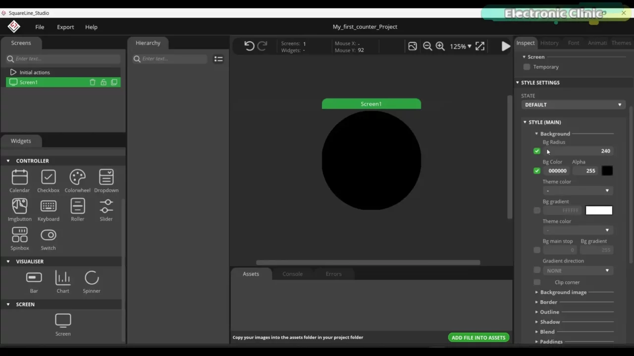
I started off by setting the Background Radius to 240.
Next, I set the Bg Color to Black.

Next, I set the border color to Red, Border width to 10.
Next, I set the Outline color to Yellow, and set the Outline width to 5.
If you want, you can also play with other properties. But I think it’s ok for now.
Once styling is complete, before adding any widgets, you first need to make sure everything is working. For this;
- First save your project.
Then, go to the Export menu and click on Export UI Files.

You can see the SquareLine Project files and folders. Now, let’s go to the UI files folder.

Great! The UI files are also generated. Let’s copy all these files and paste them into the Arduino Project folder.

Now, let’s open the Arduino file.

All the files are automatically added. Before uploading this program, first go to ui.c and change LV_COLOR_16_SWAP from 0 to 1. Otherwise, it will generate an error.
Code:
|
1 2 3 4 5 6 7 8 9 10 11 12 13 14 15 16 17 18 19 20 21 22 23 24 25 26 27 28 29 30 31 32 33 34 35 36 37 38 39 40 41 42 43 44 45 46 47 48 49 50 51 52 53 54 55 56 57 58 59 60 61 62 63 64 65 66 67 68 69 70 71 72 73 74 75 76 77 78 79 80 81 82 83 84 85 86 87 88 89 90 91 92 93 94 95 96 97 98 99 100 101 102 103 104 105 106 107 108 109 110 111 112 113 114 115 116 117 118 119 120 121 122 123 124 125 126 127 128 129 130 131 132 133 134 135 136 137 138 139 140 141 142 143 144 145 146 147 148 149 150 151 152 153 154 155 156 157 158 159 160 161 162 163 164 165 166 167 168 169 170 171 172 173 174 175 176 177 178 179 180 181 182 183 184 185 186 187 188 189 190 191 192 193 194 195 196 197 198 199 200 201 202 203 204 205 206 207 208 209 210 211 212 213 214 215 216 217 218 219 220 221 222 223 224 225 226 227 228 229 230 231 232 233 234 235 236 237 238 239 240 241 242 243 244 245 246 247 248 249 250 251 252 253 254 255 256 257 258 259 260 261 262 263 264 265 266 267 268 269 270 271 272 273 274 275 276 277 278 279 280 281 282 283 284 285 286 287 288 289 290 291 292 293 294 295 296 297 298 299 300 301 302 303 304 305 306 307 308 309 310 311 312 313 314 315 316 317 318 319 320 321 322 323 324 325 326 327 328 329 330 331 332 333 334 335 336 337 338 339 340 341 342 343 344 345 346 347 348 349 350 351 352 353 354 355 356 357 358 359 360 361 362 363 364 365 366 367 368 369 370 371 372 373 |
#define LGFX_USE_V1 #include <WiFi.h> #include "Arduino.h" #include <lvgl.h> #include <LovyanGFX.hpp> #include <Ticker.h> #include "CST816D.h" #include "do_mian.h" #include "ui.h" #include <Preferences.h> #include "I2C_BM8563.h" #define I2C_SDA 4 #define I2C_SCL 5 #define TP_INT 0 #define TP_RST -1 int counter = 0; //encoder #define ENCODER_A_PIN 19 #define ENCODER_B_PIN 18 #define SWITCH_PIN 8 //Custom key pins #define Custom_PIN 1 long position = 0; long position_tmp = 0; bool switchPressed = false; #define PI4IO_I2C_ADDR 0x43 I2C_BM8563 rtc(I2C_BM8563_DEFAULT_ADDRESS, Wire); I2C_BM8563_DateTypeDef dateStruct; I2C_BM8563_TimeTypeDef timeStruct; #define off_pin 35 #define buf_size 120 //Alarm switch sign int fal = 0; //Indicates whether the alarm has gone off int fal1 = 0; uint32_t hourValue = 0; uint32_t minuteValue = 0; class LGFX : public lgfx::LGFX_Device { lgfx::Panel_GC9A01 _panel_instance; lgfx::Bus_SPI _bus_instance; public: LGFX(void) { { auto cfg = _bus_instance.config(); cfg.spi_host = SPI2_HOST; cfg.spi_mode = 0; cfg.freq_write = 80000000; cfg.freq_read = 20000000; cfg.spi_3wire = true; cfg.use_lock = true; cfg.dma_channel = SPI_DMA_CH_AUTO; cfg.pin_sclk = 6; cfg.pin_mosi = 7; cfg.pin_miso = -1; cfg.pin_dc = 2; _bus_instance.config(cfg); _panel_instance.setBus(&_bus_instance); } { auto cfg = _panel_instance.config(); cfg.pin_cs = 10; cfg.pin_rst = -1; cfg.pin_busy = -1; cfg.memory_width = 240; cfg.memory_height = 240; cfg.panel_width = 240; cfg.panel_height = 240; cfg.offset_x = 0; cfg.offset_y = 0; cfg.offset_rotation = 0; cfg.dummy_read_pixel = 8; cfg.dummy_read_bits = 1; cfg.readable = false; cfg.invert = true; cfg.rgb_order = false; cfg.dlen_16bit = false; cfg.bus_shared = false; _panel_instance.config(cfg); } setPanel(&_panel_instance); } }; LGFX tft; CST816D touch(I2C_SDA, I2C_SCL, TP_RST, TP_INT); /*Change to your screen resolution*/ static const uint32_t screenWidth = 240; static const uint32_t screenHeight = 240; static lv_disp_draw_buf_t draw_buf; static lv_color_t buf[2][screenWidth * buf_size]; #if LV_USE_LOG != 0 /* Serial debugging */ void my_print(lv_log_level_t level, const char *file, uint32_t line, const char *fn_name, const char *dsc) { Serial.printf("%s(%s)@%d->%s\r\n", file, fn_name, line, dsc); Serial.flush(); } #endif /* Display flushing */ void my_disp_flush(lv_disp_drv_t *disp, const lv_area_t *area, lv_color_t *color_p) { if (tft.getStartCount() == 0) { tft.endWrite(); } tft.pushImageDMA(area->x1, area->y1, area->x2 - area->x1 + 1, area->y2 - area->y1 + 1, (lgfx::swap565_t *)&color_p->full); lv_disp_flush_ready(disp); /* tell lvgl that flushing is done */ } /*Read the touchpad*/ void my_touchpad_read(lv_indev_drv_t *indev_driver, lv_indev_data_t *data) { bool touched; uint8_t gesture; uint16_t touchX, touchY; touched = touch.getTouch(&touchX, &touchY, &gesture); if (!touched) { data->state = LV_INDEV_STATE_REL; } else { data->state = LV_INDEV_STATE_PR; /*Set the coordinates*/ data->point.x = touchX; data->point.y = touchY; } } Ticker ticker; //Extended IO function void init_IO_extender() { Wire.beginTransmission(PI4IO_I2C_ADDR); Wire.write(0x01); // test register Wire.endTransmission(); Wire.requestFrom(PI4IO_I2C_ADDR, 1); uint8_t rxdata = Wire.read(); Serial.print("Device ID: "); Serial.println(rxdata, HEX); Wire.beginTransmission(PI4IO_I2C_ADDR); Wire.write(0x03); // IO direction register Wire.write((1 << 0) | (1 << 1) | (1 << 2) | (1 << 3) | (1 << 4)); // set pins 0, 1, 2 as outputs Wire.endTransmission(); Wire.beginTransmission(PI4IO_I2C_ADDR); Wire.write(0x07); // Output Hi-Z register Wire.write(~((1 << 0) | (1 << 1) | (1 << 2) | (1 << 3) | (1 << 4))); // set pins 0, 1, 2 low Wire.endTransmission(); } void set_pin_io(uint8_t pin_number, bool value) { Wire.beginTransmission(PI4IO_I2C_ADDR); Wire.write(0x05); // test register Wire.endTransmission(); Wire.requestFrom(PI4IO_I2C_ADDR, 1); uint8_t rxdata = Wire.read(); Serial.print("Before the change: "); Serial.println(rxdata, HEX); Wire.beginTransmission(PI4IO_I2C_ADDR); Wire.write(0x05); // Output register if (!value) Wire.write((~(1 << pin_number)) & rxdata); // set pin low else Wire.write((1 << pin_number) | rxdata); // set pin high Wire.endTransmission(); Wire.beginTransmission(PI4IO_I2C_ADDR); Wire.write(0x05); // test register Wire.endTransmission(); Wire.requestFrom(PI4IO_I2C_ADDR, 1); rxdata = Wire.read(); Serial.print("after the change: "); Serial.println(rxdata, HEX); } //RTC function void RTC_init() { rtc.begin(); // Set custom time // I2C_BM8563_TimeTypeDef timeStruct; // timeStruct.hours = 11; // Hour (0 - 23) // timeStruct.minutes = 59; // Minute (0 - 59) // timeStruct.seconds = 0; // Second (0 - 59) // rtc.setTime(&timeStruct); // // I2C_BM8563_DateTypeDef dateStruct; // dateStruct.weekDay = 3; // Weekday (0 - 6, where 0 is Sunday) // dateStruct.month = 1; // Month (1 - 12) // dateStruct.date = 24; // Day of the month (1 - 31) // dateStruct.year = 2024; // Year // rtc.setDate(&dateStruct); } //Encoder function void updateEncoder() { static int previousState = 0; static int flag_A = 0; static int flag_C = 0; int currentState = (digitalRead(ENCODER_A_PIN) << 1) | digitalRead(ENCODER_B_PIN); if ((currentState == 0b00 && previousState == 0b01) || (currentState == 0b01 && previousState == 0b11) || (currentState == 0b11 && previousState == 0b10) || (currentState == 0b10 && previousState == 0b00)) { // foreward // if (switchPressed) { flag_A++; if (flag_A == 50) { flag_A = 0; flag_C = 0; // position++; // position_tmp=position; position_tmp = 1; } // flag_C=0; // } } else if ((currentState == 0b01 && previousState == 0b00) || (currentState == 0b11 && previousState == 0b01) || (currentState == 0b10 && previousState == 0b11) || (currentState == 0b00 && previousState == 0b10)) { // reversal // if (switchPressed) { flag_C++; if (flag_C == 50) { // position--; flag_C = 0; flag_A = 0; // position_tmp=position; position_tmp = 0; } // flag_A=0; // } } previousState = currentState; } void switchPressedInterrupt() { switchPressed = !switchPressed; } void setup() { Serial.begin(115200); /* prepare for possible serial debug */ Serial.println("I am LVGL_Arduino"); Wire.begin(4, 5); init_IO_extender(); delay(100); set_pin_io(3, true); set_pin_io(4, true); pinMode(ENCODER_A_PIN, INPUT_PULLUP); pinMode(ENCODER_B_PIN, INPUT_PULLUP); pinMode(SWITCH_PIN, INPUT_PULLUP); pinMode(Custom_PIN, INPUT); attachInterrupt(digitalPinToInterrupt(ENCODER_A_PIN), updateEncoder, CHANGE); attachInterrupt(digitalPinToInterrupt(ENCODER_B_PIN), updateEncoder, CHANGE); attachInterrupt(digitalPinToInterrupt(SWITCH_PIN), switchPressedInterrupt, FALLING); // ticker.attach(1, tcr1s); tft.init(); tft.initDMA(); tft.startWrite(); tft.setColor(0, 0, 0); tft.fillScreen(TFT_BLACK); delay(200); if (is_touch == 1) { touch.begin(); } lv_init(); #if LV_USE_LOG != 0 //lv_log_register_print_cb(my_print); /* register print function for debugging */ #endif lv_disp_draw_buf_init(&draw_buf, buf[0], buf[1], screenWidth * buf_size); /*Initialize the display*/ static lv_disp_drv_t disp_drv; lv_disp_drv_init(&disp_drv); /*Change the following line to your display resolution*/ disp_drv.hor_res = screenWidth; disp_drv.ver_res = screenHeight; disp_drv.flush_cb = my_disp_flush; disp_drv.draw_buf = &draw_buf; lv_disp_drv_register(&disp_drv); /*Initialize the (dummy) input device driver*/ if (is_touch == 1) { static lv_indev_drv_t indev_drv; lv_indev_drv_init(&indev_drv); indev_drv.type = LV_INDEV_TYPE_POINTER; indev_drv.read_cb = my_touchpad_read; lv_indev_drv_register(&indev_drv); } #if 0 /* Create simple label */ lv_obj_t *label = lv_label_create( lv_scr_act() ); lv_label_set_text( label, "Hello Arduino! (V8.0.X)" ); lv_obj_align( label, LV_ALIGN_CENTER, 0, 0 ); #else /* Try an example from the lv_examples Arduino library make sure to include it as written above. lv_example_btn_1(); */ // uncomment one of these demos // lv_demo_widgets(); // OK // lv_demo_benchmark(); // OK // lv_demo_keypad_encoder(); // works, but I haven't an encoder // lv_demo_music(); // NOK // lv_demo_printer(); // lv_demo_stress(); // seems to be OK ui_mian(); // watch #endif Serial.println("Setup done"); // delay(200); set_pin_io(2, true); pinMode(3, OUTPUT); digitalWrite(3, LOW); // pinMode(0, INPUT); // Get RTC RTC_init(); rtc.getDate(&dateStruct); rtc.getTime(&timeStruct); } //void Watch_Function(void *param) void loop() { lv_timer_handler(); /* let the GUI do its work */ } |
Now, to upload the program:
- Select ESP32C3 Dev Module.
- Select the correct communication port.
Select the Partition Scheme as Huge APP and then click on the Upload button.
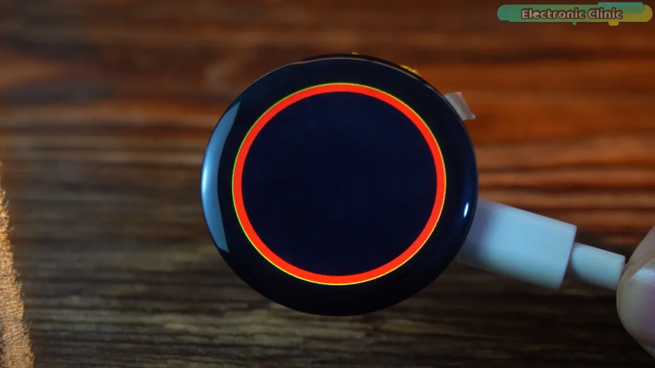
You can see the red border and the outline, which means we have done everything correctly. Now, let’s go ahead and make a counter.

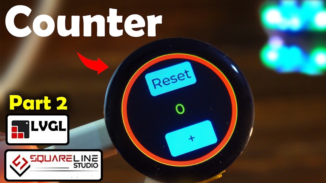
It just a basic GUI, in the Hierarchy, you can see, I have added two buttons and three labels. To make the label1 child, simply drag and drop it over the Button1. If you face any issues; you can watch the video tutorial given at the end of this article.
Tip: Since we are using default fonts, make sure to keep the text size same. First I used different size fonts but it generated an error. So, later I changed the text size of all the labels to 30.

I also changed the button’s names and name of the lable1 to btnReset, btnCounter, and lblCounter. This way, I can easily keep track of all the buttons and labels. If I used default names then it would be quite difficult for me to remember.
Our GUI is complete. Next, we are going to add events to increment and reset the counter.
I want to increament the counter when I release the button, so I am going to select the trigger type as RELEASED. Under Action, I am going to select CALL FUNCTION.

Next, click the ADD button and type the function name.

Make sure to check the box next to Do not export.
Now, follow the same steps for the Reset Button.

Save the project and export the UI Files.
Each time you generate the UI files, you will have to go to the UI files folder, copy all those files, and paste them into the Arduino project folder, make sure to replace the exiting ui files.
Now, if you go to ui_events.h, you will see the functions.

If you want to check the properties of all the widgets, you can go to ui_Screen1.c. In fact, you can not only check but also modify the values.
And if you go to ui.h, you will find all the variables.
Final Counter Code:
|
1 2 3 4 5 6 7 8 9 10 11 12 13 14 15 16 17 18 19 20 21 22 23 24 25 26 27 28 29 30 31 32 33 34 35 36 37 38 39 40 41 42 43 44 45 46 47 48 49 50 51 52 53 54 55 56 57 58 59 60 61 62 63 64 65 66 67 68 69 70 71 72 73 74 75 76 77 78 79 80 81 82 83 84 85 86 87 88 89 90 91 92 93 94 95 96 97 98 99 100 101 102 103 104 105 106 107 108 109 110 111 112 113 114 115 116 117 118 119 120 121 122 123 124 125 126 127 128 129 130 131 132 133 134 135 136 137 138 139 140 141 142 143 144 145 146 147 148 149 150 151 152 153 154 155 156 157 158 159 160 161 162 163 164 165 166 167 168 169 170 171 172 173 174 175 176 177 178 179 180 181 182 183 184 185 186 187 188 189 190 191 192 193 194 195 196 197 198 199 200 201 202 203 204 205 206 207 208 209 210 211 212 213 214 215 216 217 218 219 220 221 222 223 224 225 226 227 228 229 230 231 232 233 234 235 236 237 238 239 240 241 242 243 244 245 246 247 248 249 250 251 252 253 254 255 256 257 258 259 260 261 262 263 264 265 266 267 268 269 270 271 272 273 274 275 276 277 278 279 280 281 282 283 284 285 286 287 288 289 290 291 292 293 294 295 296 297 298 299 300 301 302 303 304 305 306 307 308 309 310 311 312 313 314 315 316 317 318 319 320 321 322 323 324 325 326 327 328 329 330 331 332 333 334 335 336 337 338 339 340 341 342 343 344 345 346 347 348 349 350 351 352 353 354 355 356 357 358 359 360 361 362 363 364 365 366 367 368 369 370 371 372 373 374 375 376 377 378 379 380 381 382 383 384 385 386 387 388 389 390 391 392 393 394 395 396 397 398 399 400 401 402 403 |
#define LGFX_USE_V1 #include <WiFi.h> #include "Arduino.h" #include <lvgl.h> #include <LovyanGFX.hpp> #include <Ticker.h> #include "CST816D.h" #include "do_mian.h" #include "ui.h" #include <Preferences.h> #include "I2C_BM8563.h" #define I2C_SDA 4 #define I2C_SCL 5 #define TP_INT 0 #define TP_RST -1 int counter = 0; //encoder #define ENCODER_A_PIN 19 #define ENCODER_B_PIN 18 #define SWITCH_PIN 8 //Custom key pins #define Custom_PIN 1 long position = 0; long position_tmp = 0; bool switchPressed = false; #define PI4IO_I2C_ADDR 0x43 I2C_BM8563 rtc(I2C_BM8563_DEFAULT_ADDRESS, Wire); I2C_BM8563_DateTypeDef dateStruct; I2C_BM8563_TimeTypeDef timeStruct; #define off_pin 35 #define buf_size 120 //Alarm switch sign int fal = 0; //Indicates whether the alarm has gone off int fal1 = 0; uint32_t hourValue = 0; uint32_t minuteValue = 0; class LGFX : public lgfx::LGFX_Device { lgfx::Panel_GC9A01 _panel_instance; lgfx::Bus_SPI _bus_instance; public: LGFX(void) { { auto cfg = _bus_instance.config(); cfg.spi_host = SPI2_HOST; cfg.spi_mode = 0; cfg.freq_write = 80000000; cfg.freq_read = 20000000; cfg.spi_3wire = true; cfg.use_lock = true; cfg.dma_channel = SPI_DMA_CH_AUTO; cfg.pin_sclk = 6; cfg.pin_mosi = 7; cfg.pin_miso = -1; cfg.pin_dc = 2; _bus_instance.config(cfg); _panel_instance.setBus(&_bus_instance); } { auto cfg = _panel_instance.config(); cfg.pin_cs = 10; cfg.pin_rst = -1; cfg.pin_busy = -1; cfg.memory_width = 240; cfg.memory_height = 240; cfg.panel_width = 240; cfg.panel_height = 240; cfg.offset_x = 0; cfg.offset_y = 0; cfg.offset_rotation = 0; cfg.dummy_read_pixel = 8; cfg.dummy_read_bits = 1; cfg.readable = false; cfg.invert = true; cfg.rgb_order = false; cfg.dlen_16bit = false; cfg.bus_shared = false; _panel_instance.config(cfg); } setPanel(&_panel_instance); } }; LGFX tft; CST816D touch(I2C_SDA, I2C_SCL, TP_RST, TP_INT); /*Change to your screen resolution*/ static const uint32_t screenWidth = 240; static const uint32_t screenHeight = 240; static lv_disp_draw_buf_t draw_buf; static lv_color_t buf[2][screenWidth * buf_size]; #if LV_USE_LOG != 0 /* Serial debugging */ void my_print(lv_log_level_t level, const char *file, uint32_t line, const char *fn_name, const char *dsc) { Serial.printf("%s(%s)@%d->%s\r\n", file, fn_name, line, dsc); Serial.flush(); } #endif /* Display flushing */ void my_disp_flush(lv_disp_drv_t *disp, const lv_area_t *area, lv_color_t *color_p) { if (tft.getStartCount() == 0) { tft.endWrite(); } tft.pushImageDMA(area->x1, area->y1, area->x2 - area->x1 + 1, area->y2 - area->y1 + 1, (lgfx::swap565_t *)&color_p->full); lv_disp_flush_ready(disp); /* tell lvgl that flushing is done */ } /*Read the touchpad*/ void my_touchpad_read(lv_indev_drv_t *indev_driver, lv_indev_data_t *data) { bool touched; uint8_t gesture; uint16_t touchX, touchY; touched = touch.getTouch(&touchX, &touchY, &gesture); if (!touched) { data->state = LV_INDEV_STATE_REL; } else { data->state = LV_INDEV_STATE_PR; /*Set the coordinates*/ data->point.x = touchX; data->point.y = touchY; } } Ticker ticker; //Extended IO function void init_IO_extender() { Wire.beginTransmission(PI4IO_I2C_ADDR); Wire.write(0x01); // test register Wire.endTransmission(); Wire.requestFrom(PI4IO_I2C_ADDR, 1); uint8_t rxdata = Wire.read(); Serial.print("Device ID: "); Serial.println(rxdata, HEX); Wire.beginTransmission(PI4IO_I2C_ADDR); Wire.write(0x03); // IO direction register Wire.write((1 << 0) | (1 << 1) | (1 << 2) | (1 << 3) | (1 << 4)); // set pins 0, 1, 2 as outputs Wire.endTransmission(); Wire.beginTransmission(PI4IO_I2C_ADDR); Wire.write(0x07); // Output Hi-Z register Wire.write(~((1 << 0) | (1 << 1) | (1 << 2) | (1 << 3) | (1 << 4))); // set pins 0, 1, 2 low Wire.endTransmission(); } void set_pin_io(uint8_t pin_number, bool value) { Wire.beginTransmission(PI4IO_I2C_ADDR); Wire.write(0x05); // test register Wire.endTransmission(); Wire.requestFrom(PI4IO_I2C_ADDR, 1); uint8_t rxdata = Wire.read(); Serial.print("Before the change: "); Serial.println(rxdata, HEX); Wire.beginTransmission(PI4IO_I2C_ADDR); Wire.write(0x05); // Output register if (!value) Wire.write((~(1 << pin_number)) & rxdata); // set pin low else Wire.write((1 << pin_number) | rxdata); // set pin high Wire.endTransmission(); Wire.beginTransmission(PI4IO_I2C_ADDR); Wire.write(0x05); // test register Wire.endTransmission(); Wire.requestFrom(PI4IO_I2C_ADDR, 1); rxdata = Wire.read(); Serial.print("after the change: "); Serial.println(rxdata, HEX); } //RTC function void RTC_init() { rtc.begin(); // Set custom time // I2C_BM8563_TimeTypeDef timeStruct; // timeStruct.hours = 11; // Hour (0 - 23) // timeStruct.minutes = 59; // Minute (0 - 59) // timeStruct.seconds = 0; // Second (0 - 59) // rtc.setTime(&timeStruct); // // I2C_BM8563_DateTypeDef dateStruct; // dateStruct.weekDay = 3; // Weekday (0 - 6, where 0 is Sunday) // dateStruct.month = 1; // Month (1 - 12) // dateStruct.date = 24; // Day of the month (1 - 31) // dateStruct.year = 2024; // Year // rtc.setDate(&dateStruct); } //Encoder function void updateEncoder() { static int previousState = 0; static int flag_A = 0; static int flag_C = 0; int currentState = (digitalRead(ENCODER_A_PIN) << 1) | digitalRead(ENCODER_B_PIN); if ((currentState == 0b00 && previousState == 0b01) || (currentState == 0b01 && previousState == 0b11) || (currentState == 0b11 && previousState == 0b10) || (currentState == 0b10 && previousState == 0b00)) { // foreward // if (switchPressed) { flag_A++; if (flag_A == 50) { flag_A = 0; flag_C = 0; // position++; // position_tmp=position; position_tmp = 1; } // flag_C=0; // } } else if ((currentState == 0b01 && previousState == 0b00) || (currentState == 0b11 && previousState == 0b01) || (currentState == 0b10 && previousState == 0b11) || (currentState == 0b00 && previousState == 0b10)) { // reversal // if (switchPressed) { flag_C++; if (flag_C == 50) { // position--; flag_C = 0; flag_A = 0; // position_tmp=position; position_tmp = 0; } // flag_A=0; // } } previousState = currentState; } void switchPressedInterrupt() { switchPressed = !switchPressed; } void setup() { Serial.begin(115200); /* prepare for possible serial debug */ Serial.println("I am LVGL_Arduino"); Wire.begin(4, 5); init_IO_extender(); delay(100); set_pin_io(3, true); set_pin_io(4, true); pinMode(ENCODER_A_PIN, INPUT_PULLUP); pinMode(ENCODER_B_PIN, INPUT_PULLUP); pinMode(SWITCH_PIN, INPUT_PULLUP); pinMode(Custom_PIN, INPUT); attachInterrupt(digitalPinToInterrupt(ENCODER_A_PIN), updateEncoder, CHANGE); attachInterrupt(digitalPinToInterrupt(ENCODER_B_PIN), updateEncoder, CHANGE); attachInterrupt(digitalPinToInterrupt(SWITCH_PIN), switchPressedInterrupt, FALLING); // ticker.attach(1, tcr1s); tft.init(); tft.initDMA(); tft.startWrite(); tft.setColor(0, 0, 0); tft.fillScreen(TFT_BLACK); delay(200); if (is_touch == 1) { touch.begin(); } lv_init(); #if LV_USE_LOG != 0 //lv_log_register_print_cb(my_print); /* register print function for debugging */ #endif lv_disp_draw_buf_init(&draw_buf, buf[0], buf[1], screenWidth * buf_size); /*Initialize the display*/ static lv_disp_drv_t disp_drv; lv_disp_drv_init(&disp_drv); /*Change the following line to your display resolution*/ disp_drv.hor_res = screenWidth; disp_drv.ver_res = screenHeight; disp_drv.flush_cb = my_disp_flush; disp_drv.draw_buf = &draw_buf; lv_disp_drv_register(&disp_drv); /*Initialize the (dummy) input device driver*/ if (is_touch == 1) { static lv_indev_drv_t indev_drv; lv_indev_drv_init(&indev_drv); indev_drv.type = LV_INDEV_TYPE_POINTER; indev_drv.read_cb = my_touchpad_read; lv_indev_drv_register(&indev_drv); } #if 0 /* Create simple label */ lv_obj_t *label = lv_label_create( lv_scr_act() ); lv_label_set_text( label, "Hello Arduino! (V8.0.X)" ); lv_obj_align( label, LV_ALIGN_CENTER, 0, 0 ); #else /* Try an example from the lv_examples Arduino library make sure to include it as written above. lv_example_btn_1(); */ // uncomment one of these demos // lv_demo_widgets(); // OK // lv_demo_benchmark(); // OK // lv_demo_keypad_encoder(); // works, but I haven't an encoder // lv_demo_music(); // NOK // lv_demo_printer(); // lv_demo_stress(); // seems to be OK ui_mian(); // watch #endif Serial.println("Setup done"); // delay(200); set_pin_io(2, true); pinMode(3, OUTPUT); digitalWrite(3, LOW); // pinMode(0, INPUT); // Get RTC RTC_init(); rtc.getDate(&dateStruct); rtc.getTime(&timeStruct); } //void Watch_Function(void *param) void loop() { lv_timer_handler(); /* let the GUI do its work */ lv_label_set_text(ui_lblCounter, String(counter).c_str()); } void ResetCounter(lv_event_t * e) { counter = 0; } void incrementCounter(lv_event_t * e) { counter++; } I have already defined a variable counter of type integer. lv_label_set_text(ui_lblCounter, String(counter).c_str()); This function updates the text of an LVGL label (ui_lblCounter) with the current value of counter, converting the integer counter to a string format. So, let’s modify it. void ResetCounter(lv_event_t * e) { counter = 0; } void incrementCounter(lv_event_t * e) { counter++; } |
These two functions will be called when we press the + and Reset buttons. So, the code is ready.
Before uploading the program, make sure to change LV_COLOR_16_SWAP from 0 to 1.

And here is our first counter!
It worked exceptionally well and I was able to increment and reset the counter.
But there was one issue: even if I would slightly touch the Reset button, the counter would reset. So, I went back to the SquareLine Studio, and changed the Reset button trigger from released to LONG_PRESSED.
Now, even if I intentionally press the Reset button, the counter is not reset unless I press it for more than 1 second. Now, the counter won’t reset if I accidently touch the Reset button.
So, that’s all about how to make a counter using SquareLine Studio and the LVGL library. In the next tutorial, we will add a second screen and make an awesome digital watch using custom fonts.
Next, read my article on how to make a digital watch.
Watch Video Tutorial:
Discover more from Electronic Clinic
Subscribe to get the latest posts sent to your email.


