Motor Sub-Circuit Protection, Isolator and Starter
Last Updated on October 25, 2023 by Engr. Shahzada Fahad
Motor Circuit
The following points have to be kept in view at the time of making the motor sub-circuit.
(1). A fuse or a circuit breaker is generally used in order to provide protection to every final sub-circuit providing supply to a motor. In the situation of using fuses, the current capacity of fuses should be twice the rating of the cable connected to the motor.
(2). All electric motors, whether A.C or D.C and whatever their horsepower value, should have a proper starting and stopping arrangement. Suitable appliances or equipment should be installed in order to isolate motors, control, and their corresponding circuits from the supply. Further, an overcurrent protection is also necessary to isolate the motor from the supply in a situation of an excess current flow.
(3). Along with all AC and DC motors having less than half horsepower rating, under-voltage protection is also necessary to be installed. In this way, whenever supply voltages fall short of an appropriate value or drop below a suitable value, this protection isolates the motor from the supply. Moreover, at the time of starting a motor, it is also necessary to keep the starting current of motors within a reasonable value limit.
(4). The voltage drops between a consumer’s terminals and motor terminals should not exceed 5%.
Control of Motors
It is necessary to install the following appliances, or accessories in order to control a motor;
Sub-Circuit Protection
The sub-circuit of any motor can be protected through the application of fuses or circuit breakers. As the value of starting current of any motor tends to be higher than its normal full load current, therefore the sub-circuit motor protection should have the capacity to let this high current pass through it without any sort of reaction. It means that the rating of sub-circuit protection (fuses or breakers) should be high up to a reasonable value. The sub-circuit protection is used very rarely in situations of the consistent type of over-loading, and it is considered effective protection against a short circuit. (i.e., it is an excellent protection against a short circuit)
If circuit breakers have been used for any sub-circuit protection, they should have the ability to pass a high starting current through the motor without getting trip (for this purpose, a time limit device is installed in them) and could also provide protection against any possible short circuit. In situations of emergencies, circuit breakers can also be used to take the task of suspension of supply.
If fuses have been used as a protection of the sub-circuit, then the application of HRC-type fuses is generally preferred. The fusing factor (ration of a minimum fusing current passing through the fuse element and its rated current, which is known as the fusing factor) of such fuses tends to be approx. 2 %. The fuse rating should not be above 4 times the full load current of the motor. However, in a situation of extreme starting current, circuit breakers should be used instead of fuses. Small-sized motors are usually provided supply through distribution boards having multi-way circuits, and application of HRC fuse is generally considered more secure in them instead of the re-wirable fuses, from the protection point of view (i.e., the use of HRC fuses is preferred instead of re-wirable fuses), because as a result of a correct selection, the chances of their melting or burning quickly eliminate.
The selection of ratings of HRC type fuses being used on three-phase motors should very carefully be done. If their rating is kept too low, any single fuse may blast in a situation of even a slight fault, or a sudden current surge (high-value current wave). As such, a three-phase motor starts operating as a single-phase motor, as a result of which any sort of damage can be expected to the motor, due to getting heated.
Isolator
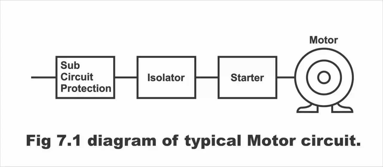
An isolator is used after the sub-circuit protection in the motors’ final sub-circuits. This has been illustrated by a specific block diagram of a motor circuit in figure 7.1. Through the application of an isolator, the motor and its control circuits can be isolated from the supply. Thus, an isolator is a device, through the application of which, a motor and its control circuits can be isolated from the supply. An isolator should be installed at a suitable place as far as possible near to the starter. If several motors are fitted along with a machine, or if numerous motors are installed at any particular place, only one isolator is used to control all these motors. However, it should be nearby the starters as far as possible. If isolators are not available, switch fuses can also be used instead of them. However, in this situation, its selected rating should be such that this switch fuse does not meltdown along with the fuses fitted on the sub-circuit, rather sub-circuit fuses have to melt first (i.e., the ratings of switch fuses being used as an isolator must be higher than the ratings of sub-circuit fuses). It has to be remembered that sub-circuit fuses are not generally installed in the presence of switch fuses. In such a condition, only switch fuses are being relied upon.
Figure 7.1 – Diagram of a typical motor circuit
Starter
In its simple form, a starter consists of a connector (which connects or disconnects motor leads to the supply wires of a motor), and overload protection. However, some additional components are also being applied along with this basic unit for getting an anticipated level of protection and control. Thus, a unit consisting of an overload and a connector is basically known as a starter. Motors less than 5 horsepower, can be operated directly from a supply line without the application of any type of starter.
There are different types of starters according to the names of different starting methods e.g., direct online (DOL) starter, resistance starters, auto starters, star delta starter, etc. Besides this, starters can either be manual or automatic, single-phase or three-phase, AC or DC. Most often, apart from an ON-OFF push button, an emergency stop button or handle, etc. is also fitted on a starter’s cover. Emergency pushbuttons are generally of reset type, which after pushing once, are required to be reset in order to restart the machine once again. Whatever, type of starter has been used, it must always be within the access of the machine operator (i.e., it should be closer to him). For small motors DOL starters, DC and single-phase AC motors resistance starters, for three-phase squirrel cage induction motors auto starter and star delta starter, whereas primary resistance starters are used for slip ring induction motors.
Over-current protection in motors is generally provided within the starters themselves. HRC fuses are also mounted on certain direct ON starters, which have a rating of 1.25 times the rating of the motor’s full load current. These fuses remain isolated from the circuit during the starter operation, and the motor gains its full speed, and its load current becomes normal, these fuses re-enter the circuit once again, i.e., connected to the circuit. Although, the rating of such fuses tends to be relatively low, however despite this they provide protection against a consistent and continuous overload. There are some starters as well, which contain thermal type or coil type overload trips. These trips are adjustable and they are normally set on approx. 10 % above the motor’s full load current.
Under-voltage protection is also being provided within a starter. For this purpose, a hold-on coil is also fitted on a starter’s handle, which energizes through the supply voltage. During normal
circumstances (i.e., when full supply voltages are being received), this coil maintains the starter handle on its original place or at its ON position. However, when supply voltage reduces from a certain value, in this situation, hold-on coil releases the starter’s handle automatically, and as such handle comes to the OFF position, and motor isolates from the supply. As a result, motor stay protected against over heating and fire even after the restoration of supply.
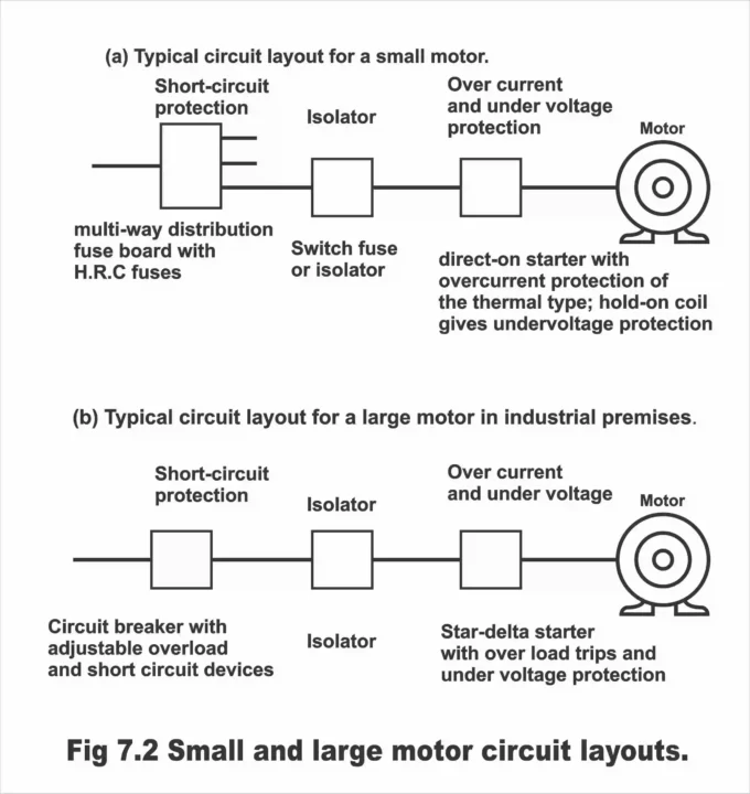
In figure 7.2, layouts of safety and controlling components being applied along with the circuits of small and large motors, have been illustrated.
Figure 7.2 – small and large motor circuit layouts
Next Topic: Calculating Cable and Fuse size for Motor Circuit
Previous Topic: How to Calculate Voltage Drop in Cables with Examples
For electronics and programming-related projects visit my YouTube channel.
Discover more from Electronic Clinic
Subscribe to get the latest posts sent to your email.