Real-Time Human Tracking Radar with mmWave Sensor and ESP32-S3 Touchscreen
Step-by-step guide to creating a real-time mmWave Human Tracking Radar ESP32 project with a responsive touch display
Last Updated on August 6, 2025 by Engr. Shahzada Fahad
Table of Contents
Description:
Real-Time Human Tracking Radar with mmWave Sensor and ESP32-S3 Touchscreen- What if you could track human movement from another room – wirelessly – using radar?
Not just movement…
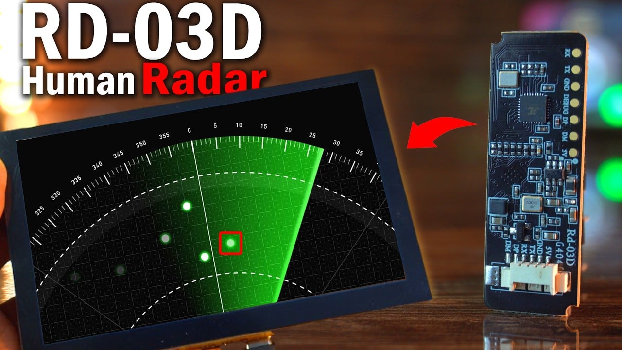
It will show exact distance, angle, and speed; live on a touchscreen, with a real radar-style animation.
![]()
Sounds futuristic?
I have built it; using the RD-03D mmWave radar and the MaTouch ESP32-S3 Parallel TFT 5” Touch Display.

In my previous article, I introduced the RD-03D mmWave radar module.
I covered everything; from how it works, to wiring, and detailed decoding of the radar data.
In that article, I didn’t just stop at decoding the radar data…
I went one step further and extracted the actual distance and angle values and printed them live on the Serial Monitor.
Product Links:
MaTouch ESP32-S3 Parallel TFT 5” Touch Display
Other Tools and Components:
ESP32 WiFi + Bluetooth Module (Recommended)
Arduino Nano USB C type (Recommended)
*Please Note: These are affiliate links. I may make a commission if you buy the components through these links. I would appreciate your support in this way!
And let me tell you; the accuracy of this sensor genuinely blew my mind.
The values were incredibly stable and precise. That gave me the confidence to try something more advanced.
So I integrated the RD-03D mmWave radar module into a real-world project; where I used human presence detection to control a bulb.
The idea was simple:
When the sensor detects a person within a certain range, it turns the light on and when the person moves away, it automatically turns the light off.
It was a practical demo of how this tiny radar module can be used for smart home automation without relying on cameras, PIR sensors, or any bulky setup.
And here’s what makes this sensor truly special:
it’s not just a motion sensor; it’s a real human presence detection sensor.
Even if someone is sitting or standing completely still, without making any visible movements; the sensor can still detect that person.
That’s the power of RD-03D millimeter-wave radar module; it can sense micro-movements that regular motion sensors simply can’t detect.
Today, I am taking that same module and building a fully portable, wireless, real-time human tracking radar system.
We are using the exact same wiring. Go ahead and check my previous article on the RD-03D mmWave Radar.
But this time, I have modified the code; turning it into a powerful two-part system:
One device acts as the radar transmitter, and the other; a touchscreen ESP32-S3 display receives and visualizes the data in real time.
Let’s talk about what’s happening behind the scenes.
On the Transmitter side, the RD-03D radar sends raw data via UART.
RD-03D Tx Side Code explanation:
I extract the X and Y positions, convert them to distance and angle, and also get the speed.
|
1 2 3 4 5 6 7 8 9 10 11 12 13 14 15 16 17 18 19 20 21 22 |
target1_x = (RX_BUF[4] | (RX_BUF[5] << 8)) - 0x200; target1_y = (RX_BUF[6] | (RX_BUF[7] << 8)) - 0x8000; target1_speed = (RX_BUF[8] | (RX_BUF[9] << 8)) - 0x10; target1_distance_res = (RX_BUF[10] | (RX_BUF[11] << 8)); target1_distance = sqrt(pow(target1_x, 2) + pow(target1_y, 2)); target1_angle = atan2(target1_y, target1_x) * 180.0 / PI; float distance_cm = target1_distance / 10.0; float angle_deg = target1_angle; int speed_cms = target1_speed; // Format as comma-separated string String data = String(distance_cm, 2) + "," + String(angle_deg, 2) + "," + String(speed_cms); Serial.println("Sending: " + data); // Broadcast data over UDP udp.beginPacket("255.255.255.255", udpPort); udp.print(data); udp.endPacket(); memset(RX_BUF, 0x00, sizeof(RX_BUF)); RX_count = 0; |
Then I format this into a simple comma-separated string — like this:
|
1 2 |
distance,angle,speed String data = String(distance_cm, 2) + "," + String(angle_deg, 2) + "," + String(speed_cms); |
This makes it super easy to parse on the receiver side.
Once the data is ready, I broadcast it wirelessly using UDP over WiFi.
But why WiFi? And why UDP?
Well, WiFi allows us to create a completely wireless system; no need for physical cables or serial connections between devices. That means more freedom, more portability, and a cleaner setup.
As for UDP, it’s lightweight and designed for real-time communication. It doesn’t require handshakes or acknowledgments like TCP does; so the data gets sent almost instantly, with minimal delay.
And even if a single packet drops occasionally, it doesn’t affect the system much; because we are sending new radar data multiple times per second.
This combination of WiFi + UDP is perfect for a fast, responsive, real-time radar system.
Radar Tx Full Code:
|
1 2 3 4 5 6 7 8 9 10 11 12 13 14 15 16 17 18 19 20 21 22 23 24 25 26 27 28 29 30 31 32 33 34 35 36 37 38 39 40 41 42 43 44 45 46 47 48 49 50 51 52 53 54 55 56 57 58 59 60 61 62 63 64 65 66 67 68 69 70 71 72 73 74 75 76 77 78 79 80 81 82 83 84 85 86 87 |
#include <WiFi.h> #include <WiFiUdp.h> #define RX_PIN 16 #define TX_PIN 17 #define BAUD_RATE 256000 const char* ssid = "fahad"; const char* password = "fahad123"; const int udpPort = 4210; WiFiUDP udp; uint8_t RX_BUF[64] = {0}; uint8_t RX_count = 0; uint8_t RX_temp = 0; int16_t target1_x = 0, target1_y = 0; int16_t target1_speed = 0; uint16_t target1_distance_res = 0; float target1_distance = 0; float target1_angle = 0; uint8_t Single_Target_Detection_CMD[12] = {0xFD, 0xFC, 0xFB, 0xFA, 0x02, 0x00, 0x80, 0x00, 0x04, 0x03, 0x02, 0x01}; void setup() { Serial.begin(115200); Serial1.begin(BAUD_RATE, SERIAL_8N1, RX_PIN, TX_PIN); Serial1.setRxBufferSize(64); WiFi.begin(ssid, password); Serial.print("Connecting to WiFi"); while (WiFi.status() != WL_CONNECTED) { delay(500); Serial.print("."); } Serial.println("\nConnected to WiFi"); udp.begin(udpPort); Serial.println("UDP broadcasting started"); Serial1.write(Single_Target_Detection_CMD, sizeof(Single_Target_Detection_CMD)); delay(200); Serial.println("Single-target detection mode activated."); RX_count = 0; Serial1.flush(); } void processRadarData() { if (RX_count >= 32) { target1_x = (RX_BUF[4] | (RX_BUF[5] << 8)) - 0x200; target1_y = (RX_BUF[6] | (RX_BUF[7] << 8)) - 0x8000; target1_speed = (RX_BUF[8] | (RX_BUF[9] << 8)) - 0x10; target1_distance_res = (RX_BUF[10] | (RX_BUF[11] << 8)); target1_distance = sqrt(pow(target1_x, 2) + pow(target1_y, 2)); target1_angle = atan2(target1_y, target1_x) * 180.0 / PI; float distance_cm = target1_distance / 10.0; float angle_deg = target1_angle; int speed_cms = target1_speed; // Format as comma-separated string String data = String(distance_cm, 2) + "," + String(angle_deg, 2) + "," + String(speed_cms); Serial.println("Sending: " + data); // Broadcast data over UDP udp.beginPacket("255.255.255.255", udpPort); udp.print(data); udp.endPacket(); memset(RX_BUF, 0x00, sizeof(RX_BUF)); RX_count = 0; } } void loop() { while (Serial1.available()) { RX_temp = Serial1.read(); RX_BUF[RX_count++] = RX_temp; if (RX_count >= sizeof(RX_BUF)) { RX_count = sizeof(RX_BUF) - 1; } if ((RX_count > 1) && (RX_BUF[RX_count - 1] == 0xCC) && (RX_BUF[RX_count - 2] == 0x55)) { processRadarData(); } } } |
Receiver Side Radar Animation Code Explanation:
On the receiver side, I am using this all-in-one MaTouch ESP32-S3 5-inch touchscreen display.
The same board runs the WiFi receiver code AND renders the radar animation using the Arduino GFX library.
|
1 2 3 4 5 6 |
// Display #define SCREEN_WIDTH 800 #define SCREEN_HEIGHT 480 #define RADAR_RADIUS 400 #define CENTER_X 400 #define CENTER_Y (SCREEN_HEIGHT - 20) |
We define the radar screen dimensions, center position, and radius; which helps us later draw the radar arcs, grid lines, and place the red dot precisely based on target distance and angle.
|
1 2 3 4 5 6 7 8 9 10 11 12 13 14 15 16 17 18 19 20 21 22 23 24 |
void drawRadarGridLineAtAngle(int angle, uint16_t color) { float rad = angle * PI / 180.0; int x = CENTER_X + RADAR_RADIUS * cos(rad); int y = CENTER_Y - RADAR_RADIUS * sin(rad); gfx->drawLine(CENTER_X, CENTER_Y, x, y, color); if (color == DARKGREY) { int tx = CENTER_X + (RADAR_RADIUS + 20) * cos(rad); int ty = CENTER_Y - (RADAR_RADIUS + 20) * sin(rad); gfx->setCursor(tx - 10, ty - 5); gfx->print(angle); gfx->print(""); } } void drawRadarArcAtRadius(int r, uint16_t color) { int prevX = -1, prevY = -1; for (int angle = 0; angle <= 180; angle++) { float rad = angle * PI / 180.0; int x = CENTER_X + r * cos(rad); int y = CENTER_Y - r * sin(rad); if (prevX >= 0) gfx->drawLine(prevX, prevY, x, y, color); prevX = x; prevY = y; } } |
We have created functions like drawRadarGridLineAtAngle() and drawRadarArcAtRadius() to draw the classic radar-style circular grid — just like you’d see on military or airport radars.
|
1 2 3 4 5 6 7 8 9 10 11 12 13 14 15 16 17 18 19 20 21 22 23 24 25 26 27 28 29 30 31 32 |
// === Full Radar Grid === void drawRadarGrid() { gfx->fillRect(0, 40, SCREEN_WIDTH, SCREEN_HEIGHT - 40, BLACK); for (int r = RADAR_RADIUS / 4; r <= RADAR_RADIUS; r += RADAR_RADIUS / 4) { drawRadarArcAtRadius(r, DARKGREY); float feet = map(r, 0, RADAR_RADIUS, 0, 300) / 30.48; gfx->setTextColor(DARKGREY); gfx->setTextSize(1); gfx->setCursor(CENTER_X + 5, CENTER_Y - r - 10); gfx->print(feet, 1); gfx->print("ft"); } for (int a = 0; a <= 180; a += 30) { drawRadarGridLineAtAngle(a, DARKGREY); } gfx->drawLine(CENTER_X - RADAR_RADIUS, CENTER_Y, CENTER_X + RADAR_RADIUS, CENTER_Y, DARKGREY); } And for extra polish, we display distance labels in feet around the radar. void drawTargetInfo() { gfx->fillRect(0, 0, SCREEN_WIDTH, 40, BLACK); gfx->setTextColor(YELLOW); gfx->setTextSize(2); gfx->setCursor(20, 10); gfx->print("Dist: "); gfx->print(targetDistance, 2); gfx->print("ft "); gfx->print("Angle: "); gfx->print((int)targetAngle); gfx->print(" "); gfx->print("Speed: "); gfx->print(targetSpeed); gfx->print("cm/s"); } |
Another function drawTargetInfo() shows the real-time numerical values at the top of the screen;
distance, angle, and speed — all in bright yellow so you can clearly monitor the target data as it streams in.
|
1 2 3 4 5 6 7 8 9 10 11 12 13 14 15 16 17 18 19 20 21 22 23 24 25 26 27 28 29 |
// === Draw Red Dot === void drawTarget(float distance_ft, float angle) { if (prevDotX > 0 && prevDotY > 0) { gfx->fillCircle(prevDotX, prevDotY, 6, BLACK); float prevR = sqrt(pow(prevDotX - CENTER_X, 2) + pow(prevDotY - CENTER_Y, 2)); for (int r = RADAR_RADIUS / 4; r <= RADAR_RADIUS; r += RADAR_RADIUS / 4) { if (abs(prevR - r) < 10) { drawRadarArcAtRadius(r, DARKGREY); } } for (int a = 0; a <= 180; a += 30) { if (abs(sweepAngle - a) <= 3) { drawRadarGridLineAtAngle(a, DARKGREY); } } } if (distance_ft > (300.0 / 30.48) || angle < 0 || angle > 180) return; float r = map(distance_ft * 30.48, 0, 300, 0, RADAR_RADIUS); // back to cm for mapping float rad = angle * PI / 180.0; int x = CENTER_X + r * cos(rad); int y = CENTER_Y - r * sin(rad); gfx->fillCircle(x, y, 5, RED); prevDotX = x; prevDotY = y; } |
The drawTarget() function places a red dot on the radar based on the incoming angle and distance.
If you move, the red dot moves with you; just like a real radar screen tracking a moving object.
|
1 2 3 4 5 6 7 8 9 10 11 12 13 14 15 16 17 18 19 20 21 22 23 24 25 26 27 28 29 30 31 32 33 |
// === Radar Sweep Trail === void drawRadarSweepTrail() { for (int i = 0; i < FADE_SEGMENTS; i++) { int idx = (fadeIndex + i) % FADE_SEGMENTS; int angle = sweepTrailAngles[idx]; float rad = angle * PI / 180.0; int x = CENTER_X + RADAR_RADIUS * cos(rad); int y = CENTER_Y - RADAR_RADIUS * sin(rad); gfx->drawLine(CENTER_X, CENTER_Y, x, y, BLACK); for (int a = 0; a <= 180; a += 30) { if (abs(angle - a) <= 3) { drawRadarGridLineAtAngle(a, DARKGREY); } } } sweepTrailAngles[fadeIndex] = sweepAngle; fadeIndex = (fadeIndex + 1) % FADE_SEGMENTS; for (int i = 0; i < FADE_SEGMENTS; i++) { int idx = (fadeIndex + FADE_SEGMENTS - 1 - i) % FADE_SEGMENTS; int angle = sweepTrailAngles[idx]; float rad = angle * PI / 180.0; int x = CENTER_X + RADAR_RADIUS * cos(rad); int y = CENTER_Y - RADAR_RADIUS * sin(rad); int brightness = 255 - (i * (255 / FADE_SEGMENTS)); uint16_t color = gfx->color565(0, brightness, 0); gfx->drawLine(CENTER_X, CENTER_Y, x, y, color); } } |
And to make it even more dynamic; we add a sweeping animation using the drawRadarSweepTrail() function. This creates a green radar beam that fades as it moves, just like in the movies.
The loop listens for any incoming data packets, decodes the comma-separated string,
and extracts the distance, angle, and speed; which are then passed to the draw functions.
That means every red dot, every sweep, every number you see on the display is coming in live from the RD-03D radar module via WiFi.
And remember; all of this is running on this single Touch Display with a built-in ESP32-S3; no PC, no external controller.
It’s a complete package; code, display, and WiFi, all in one!
Receiver Side Full Code:
|
1 2 3 4 5 6 7 8 9 10 11 12 13 14 15 16 17 18 19 20 21 22 23 24 25 26 27 28 29 30 31 32 33 34 35 36 37 38 39 40 41 42 43 44 45 46 47 48 49 50 51 52 53 54 55 56 57 58 59 60 61 62 63 64 65 66 67 68 69 70 71 72 73 74 75 76 77 78 79 80 81 82 83 84 85 86 87 88 89 90 91 92 93 94 95 96 97 98 99 100 101 102 103 104 105 106 107 108 109 110 111 112 113 114 115 116 117 118 119 120 121 122 123 124 125 126 127 128 129 130 131 132 133 134 135 136 137 138 139 140 141 142 143 144 145 146 147 148 149 150 151 152 153 154 155 156 157 158 159 160 161 162 163 164 165 166 167 168 169 170 171 172 173 174 175 176 177 178 179 180 181 182 183 184 185 186 187 188 189 190 191 192 193 194 195 196 197 198 199 200 201 202 203 204 205 206 207 208 209 210 211 212 213 214 215 216 217 218 |
#include <Arduino.h> #include <WiFi.h> #include <WiFiUdp.h> #include <Arduino_GFX_Library.h> #include "touch.h" // WiFi const char* ssid = "fahad"; const char* password = "fahad123"; const int udpPort = 4210; WiFiUDP udp; // Display #define SCREEN_WIDTH 800 #define SCREEN_HEIGHT 480 #define RADAR_RADIUS 400 #define CENTER_X 400 #define CENTER_Y (SCREEN_HEIGHT - 20) Arduino_ESP32RGBPanel *bus = new Arduino_ESP32RGBPanel( GFX_NOT_DEFINED, GFX_NOT_DEFINED, GFX_NOT_DEFINED, 40, 41, 39, 42, 45, 48, 47, 21, 14, 5, 6, 7, 15, 16, 4, 8, 3, 46, 9, 1 ); Arduino_RPi_DPI_RGBPanel *gfx = new Arduino_RPi_DPI_RGBPanel( bus, SCREEN_WIDTH, 0, 8, 4, 8, SCREEN_HEIGHT, 0, 8, 4, 8, 1, 16000000, true ); // Radar data float targetDistance = 0; // in feet float targetAngle = 0; int targetSpeed = 0; int sweepAngle = 0; bool sweepForward = true; int prevDotX = -1, prevDotY = -1; // Sweep trail #define FADE_SEGMENTS 6 int sweepTrailAngles[FADE_SEGMENTS]; int fadeIndex = 0; // Timing unsigned long lastSweepUpdate = 0; const int SWEEP_INTERVAL = 30; // === Grid drawing functions === void drawRadarGridLineAtAngle(int angle, uint16_t color) { float rad = angle * PI / 180.0; int x = CENTER_X + RADAR_RADIUS * cos(rad); int y = CENTER_Y - RADAR_RADIUS * sin(rad); gfx->drawLine(CENTER_X, CENTER_Y, x, y, color); if (color == DARKGREY) { int tx = CENTER_X + (RADAR_RADIUS + 20) * cos(rad); int ty = CENTER_Y - (RADAR_RADIUS + 20) * sin(rad); gfx->setCursor(tx - 10, ty - 5); gfx->print(angle); gfx->print(""); } } void drawRadarArcAtRadius(int r, uint16_t color) { int prevX = -1, prevY = -1; for (int angle = 0; angle <= 180; angle++) { float rad = angle * PI / 180.0; int x = CENTER_X + r * cos(rad); int y = CENTER_Y - r * sin(rad); if (prevX >= 0) gfx->drawLine(prevX, prevY, x, y, color); prevX = x; prevY = y; } } // === Full Radar Grid === void drawRadarGrid() { gfx->fillRect(0, 40, SCREEN_WIDTH, SCREEN_HEIGHT - 40, BLACK); for (int r = RADAR_RADIUS / 4; r <= RADAR_RADIUS; r += RADAR_RADIUS / 4) { drawRadarArcAtRadius(r, DARKGREY); float feet = map(r, 0, RADAR_RADIUS, 0, 300) / 30.48; gfx->setTextColor(DARKGREY); gfx->setTextSize(1); gfx->setCursor(CENTER_X + 5, CENTER_Y - r - 10); gfx->print(feet, 1); gfx->print("ft"); } for (int a = 0; a <= 180; a += 30) { drawRadarGridLineAtAngle(a, DARKGREY); } gfx->drawLine(CENTER_X - RADAR_RADIUS, CENTER_Y, CENTER_X + RADAR_RADIUS, CENTER_Y, DARKGREY); } // === Target Info === void drawTargetInfo() { gfx->fillRect(0, 0, SCREEN_WIDTH, 40, BLACK); gfx->setTextColor(YELLOW); gfx->setTextSize(2); gfx->setCursor(20, 10); gfx->print("Dist: "); gfx->print(targetDistance, 2); gfx->print("ft "); gfx->print("Angle: "); gfx->print((int)targetAngle); gfx->print(" "); gfx->print("Speed: "); gfx->print(targetSpeed); gfx->print("cm/s"); } // === Draw Red Dot === void drawTarget(float distance_ft, float angle) { if (prevDotX > 0 && prevDotY > 0) { gfx->fillCircle(prevDotX, prevDotY, 6, BLACK); float prevR = sqrt(pow(prevDotX - CENTER_X, 2) + pow(prevDotY - CENTER_Y, 2)); for (int r = RADAR_RADIUS / 4; r <= RADAR_RADIUS; r += RADAR_RADIUS / 4) { if (abs(prevR - r) < 10) { drawRadarArcAtRadius(r, DARKGREY); } } for (int a = 0; a <= 180; a += 30) { if (abs(sweepAngle - a) <= 3) { drawRadarGridLineAtAngle(a, DARKGREY); } } } if (distance_ft > (300.0 / 30.48) || angle < 0 || angle > 180) return; float r = map(distance_ft * 30.48, 0, 300, 0, RADAR_RADIUS); // back to cm for mapping float rad = angle * PI / 180.0; int x = CENTER_X + r * cos(rad); int y = CENTER_Y - r * sin(rad); gfx->fillCircle(x, y, 5, RED); prevDotX = x; prevDotY = y; } // === Radar Sweep Trail === void drawRadarSweepTrail() { for (int i = 0; i < FADE_SEGMENTS; i++) { int idx = (fadeIndex + i) % FADE_SEGMENTS; int angle = sweepTrailAngles[idx]; float rad = angle * PI / 180.0; int x = CENTER_X + RADAR_RADIUS * cos(rad); int y = CENTER_Y - RADAR_RADIUS * sin(rad); gfx->drawLine(CENTER_X, CENTER_Y, x, y, BLACK); for (int a = 0; a <= 180; a += 30) { if (abs(angle - a) <= 3) { drawRadarGridLineAtAngle(a, DARKGREY); } } } sweepTrailAngles[fadeIndex] = sweepAngle; fadeIndex = (fadeIndex + 1) % FADE_SEGMENTS; for (int i = 0; i < FADE_SEGMENTS; i++) { int idx = (fadeIndex + FADE_SEGMENTS - 1 - i) % FADE_SEGMENTS; int angle = sweepTrailAngles[idx]; float rad = angle * PI / 180.0; int x = CENTER_X + RADAR_RADIUS * cos(rad); int y = CENTER_Y - RADAR_RADIUS * sin(rad); int brightness = 255 - (i * (255 / FADE_SEGMENTS)); uint16_t color = gfx->color565(0, brightness, 0); gfx->drawLine(CENTER_X, CENTER_Y, x, y, color); } } // === Setup === void setup() { Serial.begin(115200); touch_init(); gfx->begin(); gfx->fillScreen(BLACK); WiFi.begin(ssid, password); while (WiFi.status() != WL_CONNECTED) delay(500); udp.begin(udpPort); drawRadarGrid(); } // === Loop === void loop() { char buf[128]; int size = udp.parsePacket(); if (size) { int len = udp.read(buf, sizeof(buf) - 1); if (len > 0) { buf[len] = '\0'; char* part = strtok(buf, ","); if (part) targetDistance = atof(part) / 30.48; // cm to ft part = strtok(NULL, ","); if (part) targetAngle = atof(part); part = strtok(NULL, ","); if (part) targetSpeed = atoi(part); drawTargetInfo(); } } if (millis() - lastSweepUpdate >= SWEEP_INTERVAL) { lastSweepUpdate = millis(); drawRadarSweepTrail(); drawTarget(targetDistance, targetAngle); sweepAngle += (sweepForward ? 3 : -3); if (sweepAngle >= 180) { sweepAngle = 180; sweepForward = false; } else if (sweepAngle <= 0) { sweepAngle = 0; sweepForward = true; } } } |
touch.h code:
|
1 2 3 4 5 6 7 8 9 10 11 12 13 14 15 16 17 18 19 20 21 22 23 24 25 26 27 28 |
#include <Wire.h> #include "TAMC_GT911.h" #define TOUCH_GT911 #define TOUCH_GT911_SCL 18 #define TOUCH_GT911_SDA 17 #define TOUCH_GT911_INT -1 #define TOUCH_GT911_RST 38 #define TOUCH_GT911_ROTATION ROTATION_NORMAL TAMC_GT911 ts = TAMC_GT911(TOUCH_GT911_SDA, TOUCH_GT911_SCL, TOUCH_GT911_INT, TOUCH_GT911_RST, 800, 480); void touch_init() { pinMode(TOUCH_GT911_RST, OUTPUT); digitalWrite(TOUCH_GT911_RST, LOW); delay(500); digitalWrite(TOUCH_GT911_RST, HIGH); delay(500); ts.begin(); ts.setRotation(ROTATION_NORMAL); } void TouchonInterrupt(void) { ts.isTouched = true; } |
If you need the project source codes and all the other resources you can download it from my Patreon page. I have added a link in the description below.
Practical Demonstration:
Let’s test it.

I move in front of the radar.
And look; the red dot follows my position based on distance and angle.
![]()
The values on top update in real-time as I walk; all wirelessly.
This is next-level tracking; compact, smart, and portable.
Now you have probably seen radar scanning projects that use ultrasonic sensors connected to laptops.

But here’s the problem:
- The controller stays wired to a PC.
- The laptop must stay on constantly.
- It’s not portable. Not energy-efficient. And not practical at all.
My setup?

Fully standalone.
The receiver is a single touchscreen board with built-in ESP32-S3.
You can carry it anywhere in your house.
Power it using a battery.
No PC required. No cables. Just freedom.
Now let’s look at a real-life use case.
I take the ESP32-S3 touchscreen receiver to my room… and start monitoring my lab remotely.
![]()
Suddenly; I notice movement on the radar!
I walk in to check, and guess what?
My brother is there, talking on the phone.
![]()
This is how you remotely detect presence, wirelessly, in real time.
This radar system is more than a demo; it’s a foundation.
A foundation for home automation, security, elderly care, or motion-triggered alerts.
And it’s fully portable, customizable, and battery-friendly.
So, that’s all for now.
Watch Video Tutorial:
Discover more from Electronic Clinic
Subscribe to get the latest posts sent to your email.


Mr.Fahad
Hi, My name is John and I would like to build the Real time human tracking with real touchscreen ESP32.
The touch screen is on its way and I have the RS-03D
Amazon did not have the ESP32 you listed available. But they did have this available.
Arduino Nano ESP32 with Headers [ABX00083] – ESP32-S3, USB-C, Wi-Fi, Bluetooth, HID Support, MicroPython Compatible for IoT & Embedded Projects
Will this work with your project.
Looking forward to build
Thank You,
DEX