RVDT & LVDT, Rotary Variable and Linear variable differential Transducer or transformer
Last Updated on September 12, 2021 by Engr. Shahzada Fahad
Table of Contents
RVDT, Rotary Variable differential transformer:
RVDT “Rotary Variable Differential Transformer” is a common type of electromechanical sensor that can convert the rotary motion of an object around an axis into a corresponding electrical signal. RVDT is passive transducer because it require external power source for their operation.
RVDT Construction:
An RVDT consist of a hollow cylinder with a ferromagnetically conducted core rotating in clockwise and anticlockwise direction freely between the hollow cylinder. A primary coil is wrapped around in the hollow cylinder and is energized by a constant amplitude ac source known as primary excitation. Two secondary coils having an equal number of turns are wrapped on the either side of the coil at equal distance from the primary coil and two secondary coils are connected in the series generating AC output voltage.
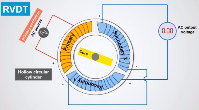
When the core is at the center called a null point zero voltage appears at the secondary output but soon as the core rotates by even the smallest amount. A differential voltage is induced at the secondary output. The phase of the output voltage is determined by the direction of the core displacement while the amplitude is determined more or less by the magnitude of the core displacement from the center. A signal conditioning circuit that is housed inside the RVDT structure and is required to convert the output to either 5V dc or 4 to 20 milli amperes. The magnitude of the differential output voltage varies with core position the value of output voltage at maximum core displacement from depend upon the amplitude of the primary excitation voltage and the sensitivity factor of the particular RVDT.
Circuit diagram and working of RVDT:
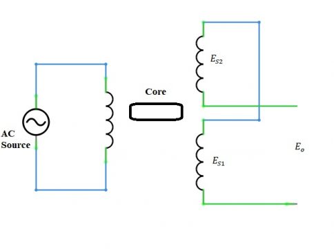
In the RVDT circuit AC excitation is connected with the primary winding. Rotary ferromagnetic core is between the winding E_S1 and E_S2 are the induced emf of the winding.
Eo= ES1 – ES2
In RVDT to produce the necessary output the sensor will produce the output voltage whose variable will be the alternating current which will be proportional to the angular displacement of the shaft. When the shaft of the RVDT will rotate the mutual inductance of the winding will be changes linearly due to angular displacement. RVDT is just like electromechanical or inductive transducer which is used to produce linear output which will be proportional to the input angular displacement. The main function of the RVDT is to detect the angular displacement and to convert it in electrical signal. RVDT imply on can type core rotary ferromagnetic core. This core will rotate between the two windings with the help of shaft.
Condition 1: Normal condition:
When the RVDT will be in normal condition the primary and core with secondary winding will be in symmetrical placing. The flux linkages in both secondary winding will be same due to their symmetrical placing with respect to core and primary winding. The ES1 and ES2 will be equal.
Eo= ES1 – ES2
In this condition the output voltage will be equal to 0 as both the voltages are equal. There this position of the RVDT is also known as Null position. when the shaft is place in the null position then the induce emf in the secondary winding will be same and the differential output will be equal to 0.
Condition 2: clockwise and anticlockwise rotation
When the core will move clockwise then the ES2 in the secondary winding will increase and when the core will rotate anticlockwise the ES11 will be increase. Thus the direction as well as the magnitude of the angular rotation can be as certain from the magnitude and phase of the transducer output voltage. The phase of the transducer voltage ( ES1 – ES2 ) can be positive or negative depending upon the rotation and this will represent the phase transducer output voltage. In case of anticlockwise the ES1 will increases and the value of ( ES1 – ES2 ) will be positive and in this case the output voltage Eo will be positive and in phase with the primary voltage.
When the core will rotate clockwise then the output voltage Eo will be negative and will be out of phase with the primary voltage ( ES1 – ES2 ) will be negative.
How to choose RVDT:
It means that on what basis we will choose the RVDT and if it is correct for particular application or not. RVDT has many advantages over
other types of sensors. We will consider certain parameters while selecting the RVDT:
Accuracy and precision of the application
In some condition the accuracy of the RVDT is imperfect and due to this reason it is not appropriate in some application. So when the high accuracy is needed so the cost of the appliance will also be increased and as the RVDT accuracy is imperfect so it will not be suitable there. So we will see the accuracy and precision while choosing the RVDT.
Working environment
RVDT is very strong and it can work in any type of environment. While other type of sensors are not very appropriate in some condition such like a tremendous change in temperature or presence of the pollution or high sound of vibration. But RVDT is very strong and it can withstand in these conditions.
Backup or Auxiliary power source
The RVDT require alternating current input so that it produces desire output reading. If there is no back-up power source then electromechanical sensor or not good choice. So when there is no back-up power source in this case we will not use RVDT sensor.
Change of Signal
Change of signal or signal conversion a sensor which can convert the data into digital output. In today world we need sensor which can convert the data in to digital form so that we can see it on PC.
So these are the parameters which we need for choosing RVDT.
Advantages of RVDT:
-
Durability:
The RVDT will be durable and robust sensing mechanism. It can be used in such places where there are extreme conditions like vibration, shock etc because it is highly durable.
-
Low cost:
The RVDT is cost effective in such situation when we have limited budget. RVDT are very cheap and are more reliable.
-
Easy to manage:
RVDT is easily operated and its maintenance is also very simple. It cannot contain complicated circuits.
-
Repeatable performance:
RVDT is small in size and compact design due to which it is fitted in many applications when there is limited space to install a sensor
-
Resolution is infinite
-
Linearity is excellent
-
Long life span
-
Consistency is high
-
High exactness
-
Construction is compact and strong
Disadvantage of RVDT:
- It restricts the usability the output of the RVDT is linear about 40° and -40° due to which its usability is limited
- The contact among the measuring exterior as well as the nozzle is not possible for all time
Application of RVDT:
RVDT has well established reputation for reliability and consistency. Therefore they are more preferred sensors. It can be used in the manufacturing and construction of heavy duty equipment and it is more preferable for it.
- Hydraulic pumps
- Valve positioning
- Rotary actuators
- Modern machine tools
- Control cockpit
- Robotics
- Process control industry
- Aircraft
- Ecological control system
- Engine fuel control
LVDT, Linear variable differential transducer or transformer:
It is a passive transducer which measures displacement. It called LVDT “Linear variable differential transducer or transformer” because it measures the linear displacement so linear motion is converted in to voltage. It consists of primary coil founded on a hollow cylindrical rod and is connected to the AC source. It consists of two winding primary winding and secondary winding. It is called differential transformer because the output of the transformer which is the difference between the voltages across the secondary winding.
Construction of the LVDT:
It consists of two secondary coils having equal number of turns and is founded on a hollow cylinder at equal distance on either side of the primary coil. The two secondary coils are connected with each other in series position. Single primary winding is connected to an alternating current source. So that the net induced emf of the two secondary coils becomes when the movable soft iron core is placed inside a hollow cylinder. The soft iron core is made up of high permeability nickel iron which is hydrogen annealed. Due to which it gets low harmonics, low null voltage and high sensitivity. In order to reduce the eddy current losses it is placed longitudinally. Position of this core with respect to the two secondary coils will affect the magnetic coupling between the primary and two secondary coils. Displacement to be measured is applied to the arm attached to the soft iron core. The Complete assembly of the Linear variable differential transducer or transformer is in stainless steel housing and the end lids provide electromagnetic and electrostatic shielding. So that if any strain magnetic and electric fields are present they cannot disturb the working of the LVDT. These are the main components which are present in the Linear variable differential transducer or transformer LVDT.
Working of LVDT:
When the AC source will be activated alternating current will starts flowing through the primary coil and the frequency of the current that is applied to the primary winding will be between 50 Hz to 20 KHz due to which varying magnetic field is produced. Now when this varying magnetic field interacts with the secondary coil and an emf is induced in the two secondary coils. So when the primary winding is excited by the alternating source it will generate induced emf in the two secondary winding.
Now let us consider the voltage induce in the secondary winding 1 is given by:
S1= ES1
The voltage induces in the secondary winding 2 is given by:
S2= ES2
We will connect these winding in series opposition. So that the output voltage that we will obtain from the LVDT will be the difference of voltages in these windings.
Eo= ES1– ES2
So in this way we will get a differential output.
Condition 1:
Initially the core is place in such a position that equal emf gets induced in both coils due to which the net emf of the two secondary coils becomes zero. This position of the core is known as null position.
ES1= ES2
Eo= ES1 – ES2 = 0
Condition 2:
If we move the core towards the right we see that the flux linking with coil S2 becomes greater than the flux linking with coil S1 as a result the emf induced in the coil S2 becomes greater than the emf induced in the coil S1 and the net emf shows a negative value.
ES1 ES2 Eo= ES1 – ES2 = negative The output voltage will be 180° out of phase with primary voltage.
Condition 3:
Similarly if we move the core towards the left we will see that the flux linking with coil S1 becomes greater than the flux linking with coil S2. As a result the emf induced in coil S1 becomes greater than the emf induced in coil S2 and the net emf show positive value. ES2 ES2
Eo= ES1 – ES2 = positive
The output voltage will be in phase with primary voltage.
Thus LVDT use the magnitude and polarity of the net emf induced to measure the displacement of its core from the null position. The amount of voltage change in either secondary winding is proportional to the amount of movement of the core. So by which displacement we are moving the core that displacement will be equal to the amount of the voltage changes in either of the secondary winding and also if we are doing this measurement we conclude that whether this voltage be in phase or out of phase through that we can see the direction of the movement of the soft iron core. So this is going to give us indication of linear motion of the soft iron core in which direction the soft iron core is moving because whenever we move the soft iron core the voltage linked with the two secondary winding is changing either it will increasing in one winding and decreasing in other winding. So by checking the magnitude and phase relationship of the output voltage we can measure the displacement of the soft iron core. The output signal may also be applied to a recorder or to a controller that can restore the moving system to its normal position.
Advantages of the LVDT:
High range:
It provides us high rate of displacement and the range of displacement that can be measure is 1.25 mm to 250 mm.
0.25 % full scale linearity = 0.003 mm
Dynamic response is slow.
Friction and electrical isolation:
The core and the coils are not too close to each other they are far apart. They are present separately and also there is no moving part and no physical contact due to which no friction is produced and also there is electrical isolation between the core and the coils. So wear and tear, no damage of the parts are produce in it. So due to which its operating life is maximum.
Immunity from external effects:
Environmental condition like pressure, temperature cannot be affect it.
High input and high sensitivity:
LVDT gives us high output and high sensitivity of about 40 V/mm
Ruggedness:
It can tolerate high shocks and vibrations
Low hysteresis
Low power consumption
Disadvantage of LVDT:
Relatively large displacement are difficult to measure
Sensitive to stray magnetic and electric fields
Dynamic response is slow
Application of the LVDT:
Primary transducers
Secondary transducers
Discover more from Electronic Clinic
Subscribe to get the latest posts sent to your email.