Step Up and Step Down Transformer Designing with Calculation
Last Updated on February 5, 2022 by Engr. Shahzada Fahad
Table of Contents
Step Up and Step Down Transformer, Overview:
Step Up and Step Down Transformer Designing with Calculation- The Step Up and Step Down Transformers are found everywhere around the globe. Even if you go ahead and open a cell phone charger, you will find a small Step Down transformer that converts 110/220Vac to around 5 Volts. You can easily find Step Down transformers in Radios, TV, VCR, CD Players, Shaver, Dish Antenna receivers, Laptop chargers, Printers, Stabilizers and so on.
Due to the heavy load shedding in countries like Pakistan and India, someone can easily find inverters. These inverters have Step Up and Step Down Transformers as you can see in the picture below.
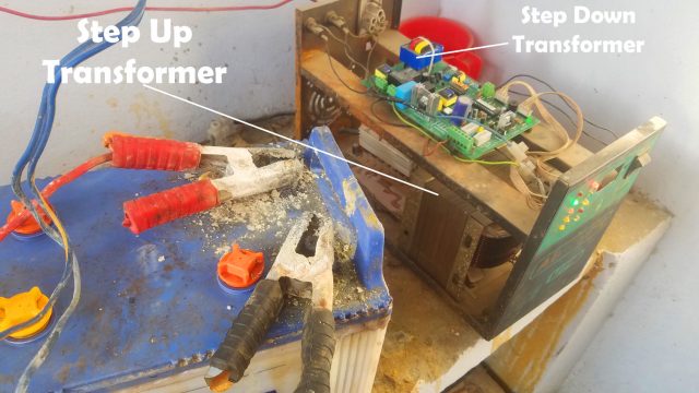
When there is no electricity the battery 12Volts is stepped Up using this Step Up Transformer. While this small Step Down transformer is used to power up the electronics. The size of the Step Up and Step Down Transformer depends on the load. As the Step Up and Step Down Transformers are one of the most frequently used Electronic Devices, this is why I decided to write a detailed article about the Step Up and Step Down Transformers, and share with you some basic knowledge of how these transformers can be designed. This article only focuses on the designing and calculation of the Step Up and Step Down Transformers. If you want to know more in depth about the Power Transformers then consider reading my article on POWER TRANSFORMER & its Types with Working Principle Explained.
Without any further delay, let’s get started!!!
Step Up Transformer:
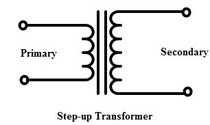
In Step up Transformer primary coil turns are less than secondary coil turns it converts the low primary voltage to a high secondary voltage i.e. it steps up the input voltage.
Example of Step- up Transformer
For example, consider a transformer in which the number of turns in the primary winding 250 and that in the secondary winding is 1000. If the alternating voltage at the primary of the transformer is 110V, then the voltage at the secondary of the transformer can be calculated using the following equation.
Vp/Vs=Np/Ns
NP (Primary turns) = 250
NS (Secondary turns)= 1000
VP (Primary voltage)= 110V
VS (secondary Voltage) =?
Using the above equation:
Vp/Vs=Np/Ns
By re-arranging the equation we get:
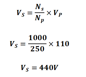
From the above example we can see that input voltage is step-up from 110v to 440v
Advantages of step-up transformers
The benefits of the step-up transformers are the following
-
Power transmission
Step-up transformers step up the voltage to transmit electricity over a long distance. The Electricity travels thousands of kilometers before it reach our homes. So there is loss of power across lines so for this purpose the voltage is step up so that voltage is easily transmitted without any loss.
-
No starting time
A step-up transformer start work without any delays.
-
Non-stop work
Step-up transformer work in power distribution system without any break it works constantly.
Step-down Transformer:
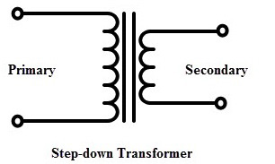
In step-down transformer the Primary turns are greater than Secondary turns it convert the voltage level from higher level to lower level. Step-down transformers are used in distribution networks it step down high grid voltage low voltage that can be used for home appliances.
The number of primary and secondary turns decides how much voltage is to be decreased.
If the ratio of turns given is 2:1 which means that the number of turns at primary winding is of two time of the secondary winding then the output voltage will be half of the input voltage and current will become double.
The overall power of the transformer will be remain same only voltage level will be decreased. It does not produce voltage it decrease the voltage level by increasing the current. For example if the turn’s ratio of transformer is 1:2 it wills half the output voltage by doubling the current.
Power in primary coil = Power in secondary coil
VP x IP = VS x IS
Vp/Vs = Is/Ip
Example of Step- down Transformer
For example, consider a transformer in which the number of turns in the primary winding 2500 and that in the secondary winding is 1500. If the alternating voltage at the primary of the transformer is 220V, then the voltage at the secondary of the transformer can be calculated using the following equation.
Vp/Vs = Np/Ns
NP (Primary turns) = 2500
NS (Secondary turns)= 1500
VP (Primary voltage)= 220V
VS (secondary Voltage) =?
Using the above equation:
Vp/Vs = Np/Ns
By re-arranging the equation we get:
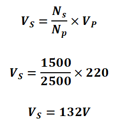
From the above example we can see that input voltage is step-down from 220v to 132v
Step-down transformer uses:
- All the transformers which we see near our homes, street, villages or cities are step down transformers. They step down 11kV to 220V for distributing it to our homes.
- Adapters use step down transformer before the wide usage of switching power supplies.
Terms Related to Transformer design:
Flux density:
Magnetic flux density is defined as magnetic flux passing through a certain area taken to perpendicular to the field. B is also known as magnetic field induction
Current density:
It is defined as the amount of electric current (charge flow in amperes) flowing through a unit value of the cross-sectional area. Current density is vector quantity, because it is specified with magnitude and a direction. It is denoted by J. it is measured in amperes/m2.
Mathematical form:
Current density (J) = Current (I)/Area (A)
For example
If 60 amperes of current is flowing through a conductor with a given area of 10 m2, what is the current density?
Answer:
The current, I = 60 amps and the area A = 10 m2.
J=I/A
J=60/10
J=6Amps/m2
Designing transformer:
To design transformer we need following Calculations:
- Area of cross section(iron)
- Number of primary turns
- Number of secondary turns
- Diameter of Primary conductor
- Diameter of secondary conductor
Assumptions
We will assume the following values for designing transformer:
Efficiency 80%
Flux density= 1.2wb/m2
Current density = 2.5wb/m2
Voltage density = 0.5%
Stack factor=0.9
Step-down Transformer design/ calculation 220V to 110:
Rating
110VA 220/110 v
Secondary voltage rating=110VA
Secondary voltage= 110V
Secondary winding current =Voltage rating/Secondary voltage
Secondary winding current =110VA/110V
=1A
Current density= Current(I) / Area
Area of Secondary Conductor = Current(I) / Current density(j)
=1/2.5 = 0.4mm2
Diameter of secondary conductor
As we know that
A=πr^2
now we know that r=d/2
A=π〖(d/2)〗^2
A=π〖d/4〗^2
4×A=πd^2
d^2=(4×A)/π
Taking square root on both sides
d=√((4×A)/π)
By putting the values we get
d=√((4×0.4)/π)
d=0.71mm
From this value we will select standard wire gauge
Now we will calculate the primary winding voltage
Primary (VA)= (Secondary (VA))/Efficiency
Primary (VA)= 110VA/0.8
Primary (VA)= 137.5 VA
We will take it approximately 140VA
Net area of cross section=√(Primary(VA))
Net area of cross section=√137.5
Net area of cross section=12 mm^2
Actual Area= (Net Area)/(Stack Factor)
Actual Area= 12/0.9
Actual Area= 13.33 mm^2
Primary current=(Primary VA)/(Primary Voltage)
Primary current=140/220=0.64A
Current density = (Current(I))/Area
Area of Primary Conductor = (Current (I))/(Current density (J))
Area of Primary Conductor = 0.64/2.5
Area of Primary Conductor = 0.26 mm^2
Diameter of Primary conductor
As we know that
A=πr^2
now we know that r=d/2
A=π〖(d/2)〗^2
A=π〖d/4〗^2
4×A=πd^2
d^2=(4×A)/π
Taking square root on both sides
d=√((4×A)/π)
By putting the values we get
d=√((4×0.26)/π)
d=0.56mm
Number of turns for Primary:
We will use emf per turn formula
emf per turn=4.44×N×B_max×f×A
N=(emf per turn)/(4.44×B_max×f×A)
N=220/(4.44×1.2×50×13.33)
N=620turns
Number of turns for Secondary:
We will use emf per turn formula
emf per turn=4.44×N×B_max×f×A
N=(emf per turn)/(4.44×B_max×f×A)
N=110/(4.44×1.2×50×13.33)
N=310 turns
Due to Voltage regulation voltage it secondary side can be fluctuate increase and decrease so we will fluctuate the turns also so we will use the voltage density value which is 0.5.
Actual turns=5/100×310=15.5=16
Total turns at secondary=310+16=326 turns
Step-down Transformer design/ calculation 220V to 12V:
Assumptions
We will assume the following values for designing transformer:
Efficiency 80%
Magnetic Flux density=B_m= 1 to 1.2 wb⁄m^2
Current density = 2.2 to 2.4 wb⁄〖mm〗^2
Design
Power Rating = 50VA
Primary voltage= 230V
Secondary voltage= 12V
Primary side Calculation:
Primary winding current =(Voltage rating)/(Primary voltage)
Primary winding current =50VA/230V
Primary winding current = 0.23 A
Size of Primary Conductor = (Current (I))/(Current density (J))
Size of Primary Conductor = 0.23/2.3
Size of Primary Conductor = 0.1 mm^2
Number of Turns = turns per volt × volt
Turns per Volt = 1/(4.44×B_max×f×A)
Area of bobbin= A= 2.26 〖inch〗^2
Area of bobbin= A= 0.00145161 m^2
By putting the values
Turns per Volt = 1/(4.44×2.3×50×0.00145161)
Turns per Volt = 2.6 turns per volt
Number of Turns = turns per volt × volt
Number of Turns = 2.6 × 230
Number of Turns = 600 turns
Total wire length = No of turns × Perimeter of bobbin
Total wire length = 600 × 7 inch
Total wire length = 4200 inch
Total wire length = 106 m
Volume of Conductor= Area × length
Volume of Conductor= 0.1 ×〖10〗^(-6) × 106
Volume of Conductor= 1.06 ×〖10〗^(-6) m^3
Weight= density × volume
Density of copper= 8960
Weight= 8960 × 1.06 ×〖10〗^(-6)
Weight= 100 gram
Secondary side Calculation:
Power rating = 50VA
Secondary Voltage= 12V
Secondary winding current =(Voltage rating)/(Secondary voltage)
Primary winding current =50VA/12V
Secondary winding current = 4.2 A
Size of Secondary Conductor = (Current (I))/(Current density (J))
Size of Secondary Conductor = 4.2/2.3
Size of Secondary Conductor = 1.8 mm^2
Number of Turns = turns per volt × volt
Turns per Volt = 1/(4.44×B_max×f×A)
Area of bobbin= A= 2.26 〖inch〗^2
Area of bobbin= A= 0.00145161 m^2
By putting the values
Turns per Volt = 1/(4.44×2.3×50×0.00145161)
Turns per Volt = 2.6 turns per volt
Number of Turns = turns per volt × volt
Number of Turns = 2.6 × 12
Number of Turns = 32 turns
Total wire length = No of turns × Perimeter of bobbin
Total wire length = 32 × 7 inch
Total wire length = 224 inch
Total wire length = 6 m
Volume of Conductor= Area × length
Volume of Conductor= 1.83 ×〖10〗^(-6) × 6
Volume of Conductor= 1.098 ×〖10〗^(-5) m^3
Weight= density × volume
Density of copper= 8960
Weight= 8960 × 1.098 ×〖10〗^(-6)
Weight= 0.098 Kg
Step-Up Transformer design/ calculation 12V to 220V:
Efficiency 90%
Magnetic Flux density=B_m= 1 to 1.2 wb⁄m^2
Current density = 2.2 to 2.4 wb⁄〖mm〗^2
Design
Power Rating = 50VA
Primary voltage= 12V
Secondary voltage= 220V
Secondary Current= 4A
Primary side Calculation:
Secondary(VA)= output voltage × output current
Secondary(VA)= 220× 4
Secondary(VA)= 880VA
Area of Conductor = (Current (I))/(Current density (J))
Area of Conductor = 4/2
Area of Conductor = 2 mm^2
Diameter of conductor
As we know that
A=πr^2
now we know that r=d/2
A=π〖(d/2)〗^2
A=π〖d/4〗^2
4×A=πd^2
d^2=(4×A)/π
Taking square root on both sides
d=√((4×A)/π)
By putting the values we get
d=√((4×2)/π)
d=1.596mm
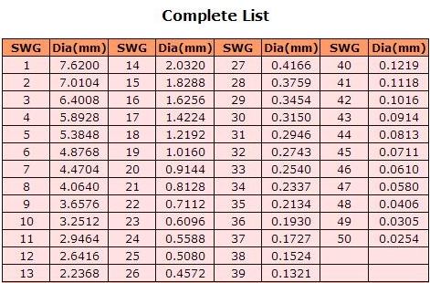
From the above table we will select SWG of wire as the diameter is 1.596mm for which SWG is 16.
Primary (VA) =(Secondary (VA))/efficiency
Primary (VA) =880/0.9
Primary (VA) =977.7 VA
Primary current =(Primary (VA))/(Primary volt)
Primary current =978/12
Primary current =81.5 A
Area of Conductor = (Current (I))/(Current density (J))
Area of Conductor = 81.5/2
Area of Conductor = 40.75 mm^2
Diameter of conductor
As we know that
A=πr^2
now we know that r=d/2
A=π〖(d/2)〗^2
A=π〖d/4〗^2
4×A=πd^2
d^2=(4×A)/π
Taking square root on both sides
d=√((4×A)/π)
By putting the values we get
d=√((4×40.75)/π)
d=7.20 mm
From the above table we will select SWG of wire as the diameter is 7.20 mm for which SWG is 1.
Core Area Calculation:
Flux density of iron core is 65000
Calculating Turn per volt per square inch
N= 〖10〗^8/(4.44×B_max×f)
N=〖10〗^8/(4.44×6500×50)
N=6.93
We will take turn per volt approximately equal to N=7
Total calculated winding area= 11 square inch
CA=(WA(winding area))/(FG(window area))
CA=11/(3×1)
CA=3.7 square inch
Stack=(Core cross section area (CA))/(E(core width of canter Limb)×Sf)
Sf=stacking factor
Stack=(3.7)/(2×0.9)
Stack=2 inch
Bobbin size =2”×2” Core 7
Turn Per Volt=7/(3.7)=1.89 TPV
Number of Primary Turns = turns per volt × volt
Number of Primary Turns = 1.89 × 12= 23 turns
Number of Primary Turns = 1.89 × 220× 1.03= 429 turns
Where 1.03 is power drop voltage
Examples Related To Transformer:
Example 1:
A transformer has 40 windings in its primary core and 30 in its secondary coil. If the primary voltage is 220 V, find the secondary voltage.
Answer:
By Using the following equation we will calculate the secondary voltage:
N_1/N_2 =V_1/V_2 =I_2/I_1
N_1/N_2 =V_1/V_2
V_2=N_1/N_2 ×V1
V_2=40/30×220
V_2=293.33V
Example 2:
A single phase 2300/230 V, 50Hz core type transformer has core section area 0.05m^2. If flux density is 1.1 wb⁄m^2 . Calculate the number of turns on primary and secondary.
Solution:
Primary Voltage= V_p=2300V
Secondary Voltage= V_s=230V
f=50Hz
Area=0.05m^2
B=1.1 wb⁄m^2
Emf induced on primary side
V_p= 4.44×Φ_max×f×N_1
Φ_max=BA
Φ_max=1.1×0.05
Φ_max=0.055wb
N_1=V_p/(4.44×Φ_max×f)
N_1=2300/(4.44×0.055×50)
N_1=188.37
So the number of turns on primary side is 188 turns
N_2=V_p/(4.44×Φ_max×f)
N_2=230/(4.44×0.055×50)
N_2=18.83
So the number of turns on primary side is 19 turns
Example 3:
A single phase transformer has 4000 primary and 1000 secondary turns. The core area is 60〖cm〗^2. If the primary winding is connected to a frequency 50Hz supply at 520V. Calculate
a) flux density in core
b) Turns ratio
c) Voltage in Secondary coil
d) E.M.F induced per turn
Solution:
N_1=400
N_2=1000
Area=60cm^2
Area=60×〖10〗^(-4) m^2
f=50Hz
V_p= 520V
a) Peak value of flux density in core
V_p= 4.44×Φ_max×f×N_1
Φ_max=BA
B= Φ_max/A
To calculate flux density we fill first calculate maximum flux
Φ_max=V_p/(4.44×f×N_1 )
By putting the values
Φ_max=520/(4.44×50×400)
Φ_max=0.0058558wb
B=Φ_max/A
B=0.0058558wb/(60×〖10〗^(-4) m^2 )
B=0.9759wb⁄m^2
b) Transformation ratio
N_1=400
N_2=1000
Transformation ratio=N_2/N_1
Transformation ratio=1000/400
Transformation ratio=2.5
c) Voltage induced in secondary
V_p/V_s =N_p/N_s
By re-arranging the equation:
V_s=〖V_p×N〗_s/N_p
V_s=520×2.5
V_s=1300V
d) E.M.F induced per turn
V_p/N_p =520/400 =1.3 volts per turn
V_s/N_s =1300/1000 =1.3 volts per turn
So, that’s all for now. I hope you have learned something new from this article. Now you can easily design your own 12V and 2Amp Step Down Transformer based power supply for an Arduino based project. Don’t forget to Subscribe to my website and YouTube channel “Electronic Clinic”.
Discover more from Electronic Clinic
Subscribe to get the latest posts sent to your email.
assalam o alaikum
janab kiya transformer se mutaaliq urdu book aap desakte hen
assalam o alaikum
janab kiya aap transformer se mutalliq urdu book de sakte hen
https://www.electroniclinic.com/step-up-and-step-down-transformer-designing-with-calculation/#comment-24888