Superposition Theorem with 10+ Solved Examples
Last Updated on June 1, 2024 by Engr. Shahzada Fahad
Table of Contents
What is the Superposition Theorem?
Superposition Theorem with 10+ Solved Examples- Superposition means a method through which a circuit is resolved at a time under the effect of just one out of several energy sources installed on the circuit and then adding up the effects of all these sources ultimately.
Under superposition theorem, solution of linear networks which consist of one or more than one current or voltage sources, is more beneficial. Because, under this method, unlike the Kirchhoff’s law, there is no need of solving too many equations.
Remember that by linear network we mean such a network, wherein if the relation between the two quantities (i.e., current and voltage) found if reflected through a graph, it will be in the shape of a straight line. That’s both the quantities increase or decrease simultaneously. Therefore, superposition theorem can be described in the following words;
(I). In any network containing more than one sources (voltage or current), the current in or the potential difference across any branch can be found by considering each source separately and adding their mutual effects, omitted sources and e.m.f are replaced by short circuits and excluded current sources by the open circuits.
In other words, the current through or voltage across an element in a linear bilateral network is equal to the algebraic sum of the currents or voltage produced independently by each source.
(II). According to superposition theorem, if several e.m.f are operating simultaneously in any linear network, then every single e.m.f is works absolutely independently and separately (just as if other e.m.f are not present in the circuit). The current value in any conductor equals to the algebraic sum of currents flowing as a result of e.m.fs. Just similarly, voltages found across any conductor equals to the algebraic sum of these voltages, which an e.m.f source provides at a time, when it is operating in the circuit single- handedly. In other words, the current flowing through any conductor of a network or voltages found across it, are obtained through combination (or through super positioning them) of currents and voltages as a result of e.m. fs existing on the network. Remember that superposition theorem is only used in linear networks, where the relation between current and voltages tend to be directly proportional under the ohm’s law.
(III). A network, wherein there are more than one e.m.f sources (generators or batteries), then current flowing on any particular point tends to be the sum of currents flowing towards that place through all sources, provided every source is treated separately, and rest of the sources converted momentarily to equivalent internal resistances.
The superposition theorem states that the current or the voltage present in a component of a linear network is equal to the sum of currents or voltages working independently or separately.
Explanation How to Apply Superposition Theorem?
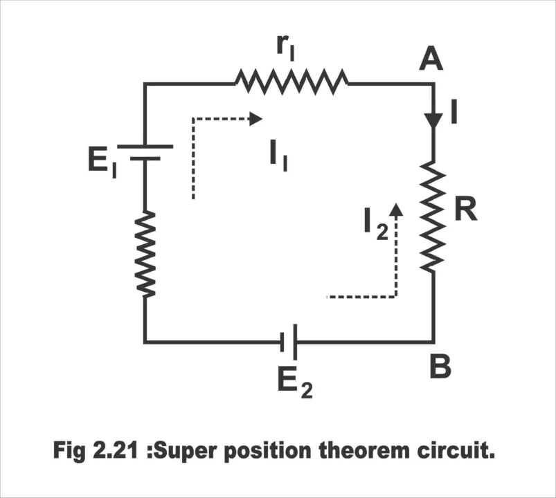
Through Superposition theorem, current provided to a linear resistor via more than one electric source can be determined. In figure 2.21, two energy sources E1 and E2 have been shown, which provide supply to resistor R. Through Kirchhoff’s law, this relation can be written as follows;
IR + Ir1 + Ir2 = E1 – E2
Figure 2.21 – Superposition theorem circuit
According to this equation, the following current flows through resistor R.
I = E1 / R + r 1 + r 2 – E 2 / R + r 1 + r 2
Here, E 1/ R + r 1 + r 2 is the current which flows through R and which is provided by E1 source, while E2 is short circuit. Whereas E 2 / R + r 1 + r 2 current, is that current which is provided by E2 source, while E1 is short circuit. Let us assume that these currents are I1 and I2 respectively. Then,
I = I1 +I2
The equation mentioned above, indicates that if both e.m. f installed on a circuit work simultaneously, then resulting current “I” flowing through R will be obtained through super posing currents I1 and I2, generated two individuals e.m. fs E1 and E2. Remember that this principle can be applied on any number of e.m. fs and this superposition theorem is applicable only for linear circuits (filaments lamps and thermocouples are not linear elements). The following arrangement is used for solving any circuit through a super position method.
First of all, an energy source is selected
Assume all other sources (voltages or currents) having been omitted from the circuit
Treat source voltages as short
Treat source currents as open
Let the resistances of removed sources be in the circuit
Determine the current passing through every element or voltages found parallel to it. Further, directions and polarities should also be taken into consideration.
Repeat the steps from 1 to 4 for every source
Add individual results algebraically (keeping directions as well as polarities in view)
Superposition Theorem Solved Example
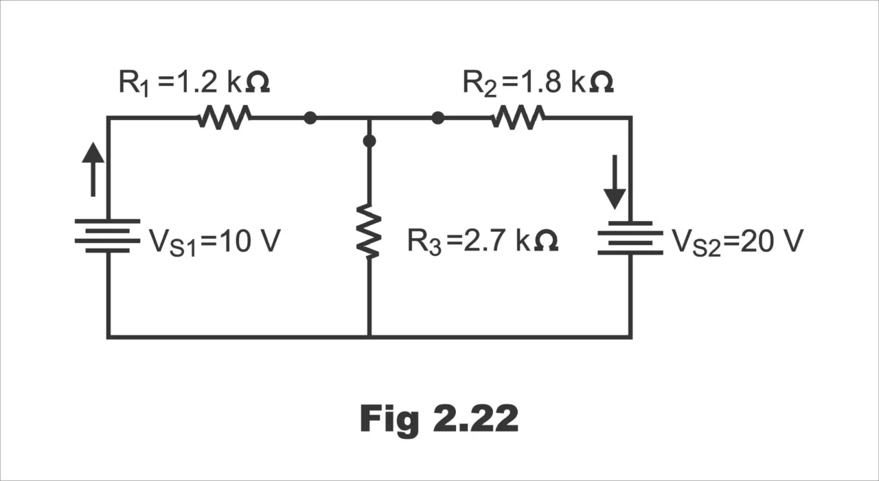
Example 1; What are the currents in the circuit in fig. 2.22?
Fig. 2.22
Solution;
Select sources VSI and redraw the circuit with VS2 removed, as in fig. 2.23.
Fig. 2.23
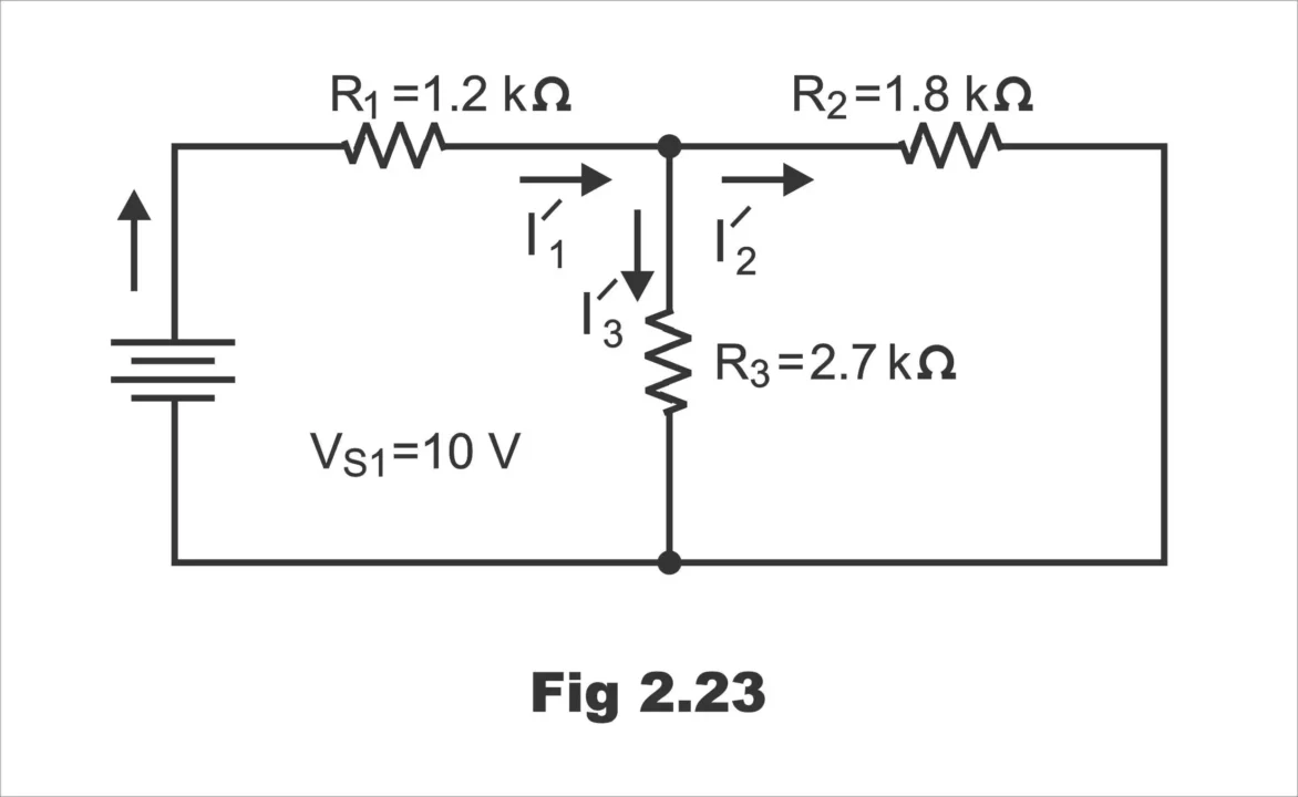
Calculate the current components due to V1
I’ 1 = VSI / R1 + R2 R3/ R2 + R3 = 10 V / 1.2 KΩ + 1.8 KΩ x 2.7 KΩ/ 1.8 KΩ + 2.7 KΩ = 4.386 mA
I’2 = I’1 R3 / R2 + R3 = 4.386 mA 2.7 KΩ/ 1.8 KΩ + 2.7 KΩ = 2.632 Ma
I’3 = I’1 – I’2 = 4.386 mA – 2.632 mA = 1.754 mA
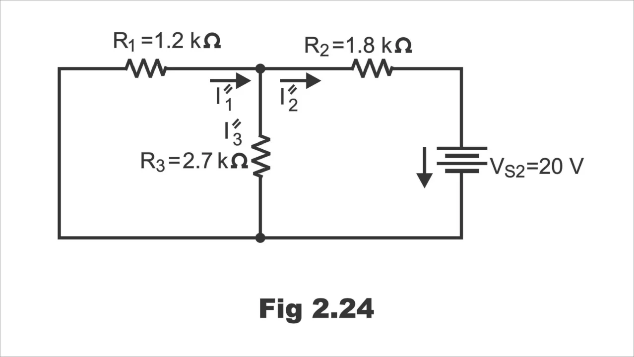
Select source VS2 and redraw the circuit with VS1 removed as in calculate the current components due to VS2.
I”2 = VS2 / R2 + R1 R3 / R1 + R3 = 20 V / 1.8 KΩ + 1.2 KΩ X 2.7 KΩ/ 1.2 KΩ + 2.7 KΩ = 7.602 mA
I “1 = I” 2 R3 / R1 + R3 = 7.602 mA 2.7 KΩ/ 1.2 KΩ + 2.7 KΩ = 5.263 mA
I” 3 = I” 2 – I” 1 = 7.602 mA – 5.263 mA = 2.339 mA
Fig. 2.24
The actual current in any element is the sum of its components, taking into account their relative directions.
I1 = I’ 1 + I” 1 = 4.386 mA + 5.263 mA = 9.649 mA to the right
I2 = I’2 + I” 2 = 2.632 mA + 7.602 mA = 10.23 mA to the right
I3 = I” 3 – I’ 3 = 2.339 mA – 1.754 mA = 0.585 mA upward
Example 2; What are the currents in the circuit in fig. 2.25? (The current direction arrows ere added after the solution was obtained)
Fig. 2.25
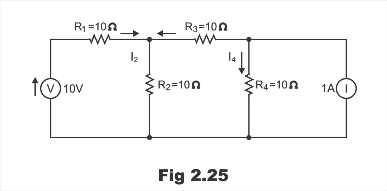
Solution;
The voltage generator on its own gives fig. 2.26
Fig. 2.26
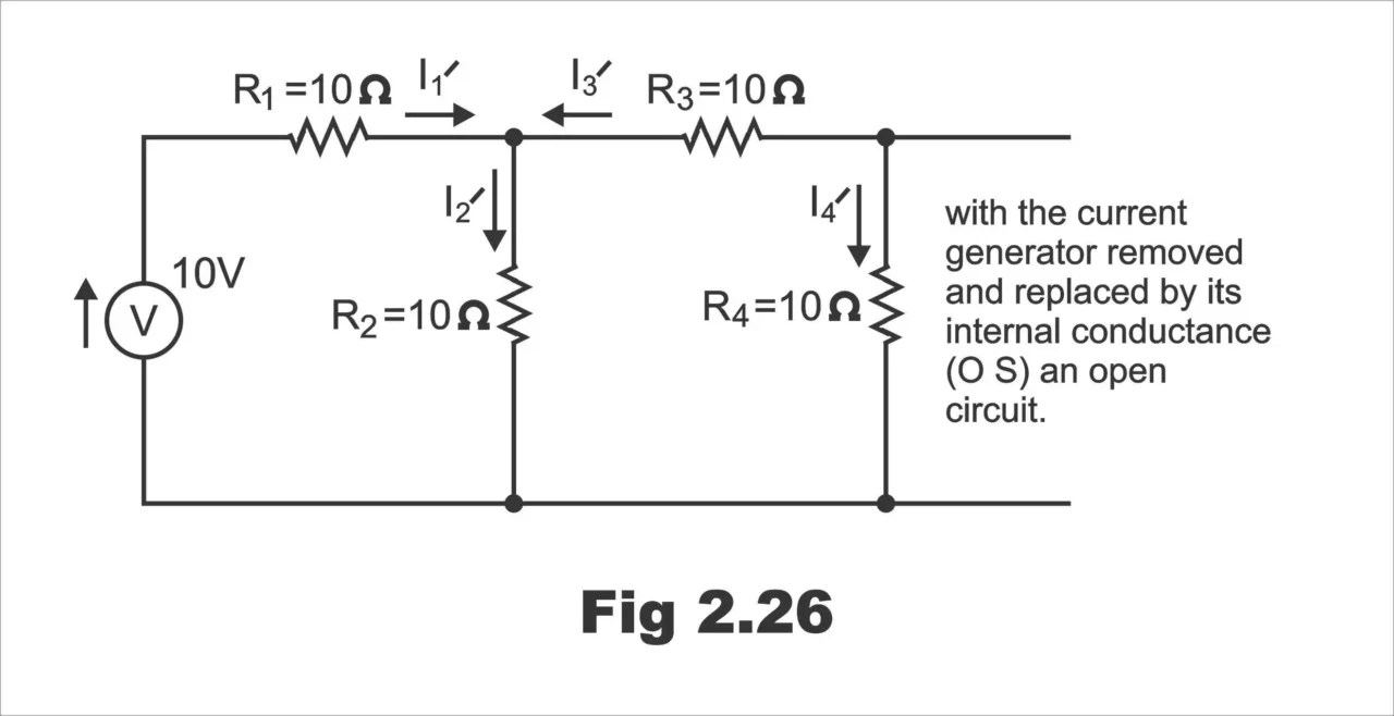
I’ 1 = V / R1 + R2 (R3 + R4) / R2 + R3 + R4 = 10 V / 10 Ω + 10 Ω x 20 Ω/ 30 Ω = 0.6 A
I’2 = I’1 R3 + R4 / R2 + R3 + R4 = 0.6 A 20 Ω/ 30 Ω = 0.4 A
I’3 = I’4 = I’1 – I’2 = 0.6 A – 0.4 A = 0.2 A
The current generator on its own gives fig. 2.27
Fig 2.27
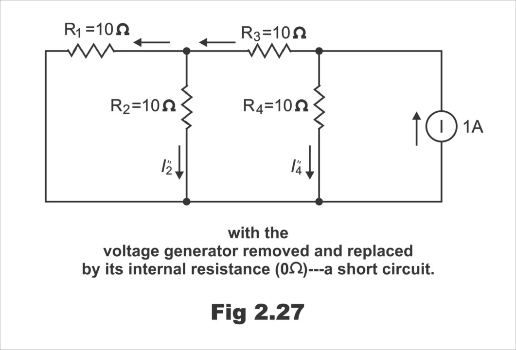
Apply the current divider principle
I”3 = I R4 / R3 + R1 R2 / R1 + R2 + R4 = 1 A 10 Ω / 25 Ω = 0.4 A
I”1 = I’ 2 = I” 3 / 2 = 0.2 A
I” 4 = I – I” 3 = 1 A – 0.4 A = 0.6 A
The total currents are
I1 = I’ 1 – I” 1 = 0.6 A – 0.2 A = 0.4 A
I2 = I’2 + I” 2 = 0.4 A + 0.2 A = 0.6 A
I3 = I” 3 – I’ 3 = 0.4 A – 0.2 A = 0.2 A
I4 = I’ 4 + I” 4 = 0.2 A + 0.6 A = 0.8 A
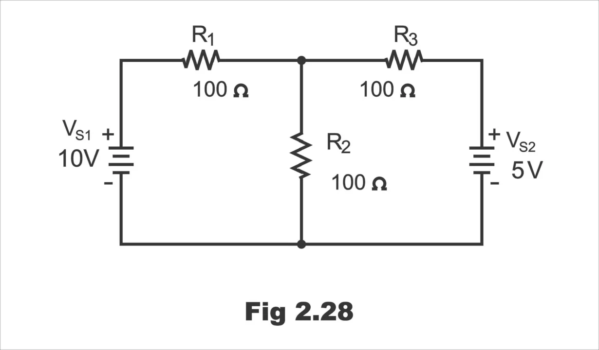
Example 3; Find the current in R2 of figure 2.28 by using the superposition theorem.
Fig. 2.28
Solution;
First, by replacing VS2 with a short, find the current in R2 due to voltage source VS1, as shown in figure 2.29
To find I2, we can use the current divider formula. Looking from VS1,
R1 = R1 + R3 / 2 = 100 Ω = 100 Ω = 150 Ω
IT = VS1 / RT = 10 V/ 150 Ω = 0.0667 A = 66.7 mA
The current in R2 due to VS1 is
I2 = [R3 / R2 + R3] IT = [100 Ω / 200 Ω] 66.7 mA = 33.3 mA
Fig. 2.29
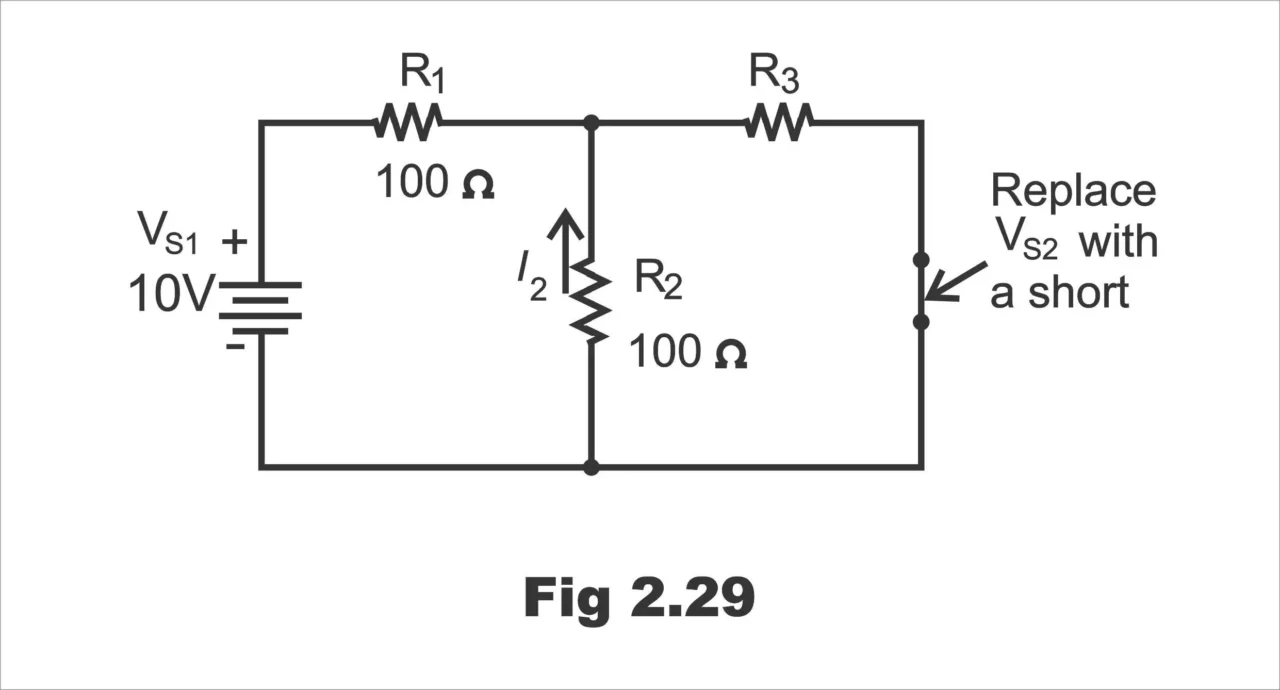
Note that this current is upward through R2.
Next find the current in R2 due to voltage source VS2 by replacing VS1 with a short, as shown in figure 2.30.
Fig. 2.30
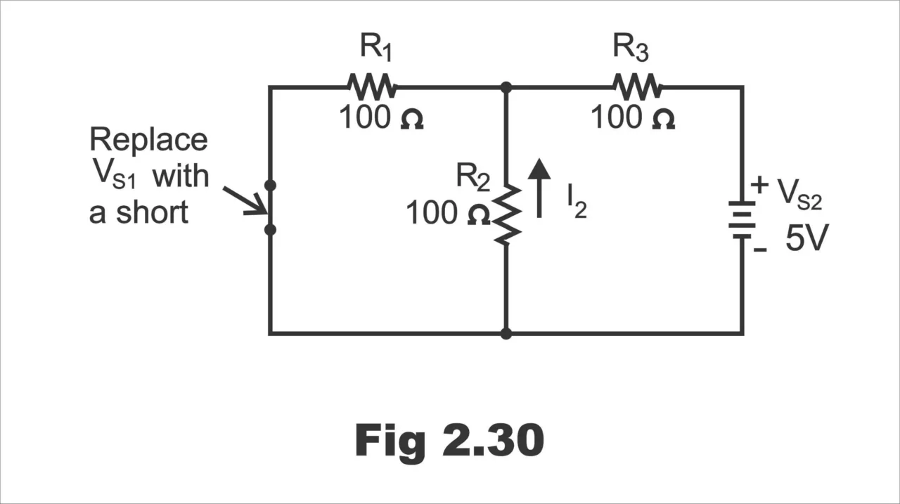
Looking from VS2, RT = R3 + R1 / 2 = 100 Ω + 50 Ω = 150 Ω
IT = VS2 / RT = 5V / 150 Ω = 0.0333 A = 33.3 mA
The current in R2 due to VS2 is
I2 = [R1 / R1 + R2] IT = [100 Ω / 200 Ω] 33.3 mA = 16.7 mA
Note that this current is upward through R2
Both component currents are upward through R2, so they have the same algebraic sign. Therefore, we add the values to get the total current through R2;
I2 (total) = I2 (due to VS1) + I2 (due to VS2)
= 33.3 mA + 16.7 mA = 50 mA
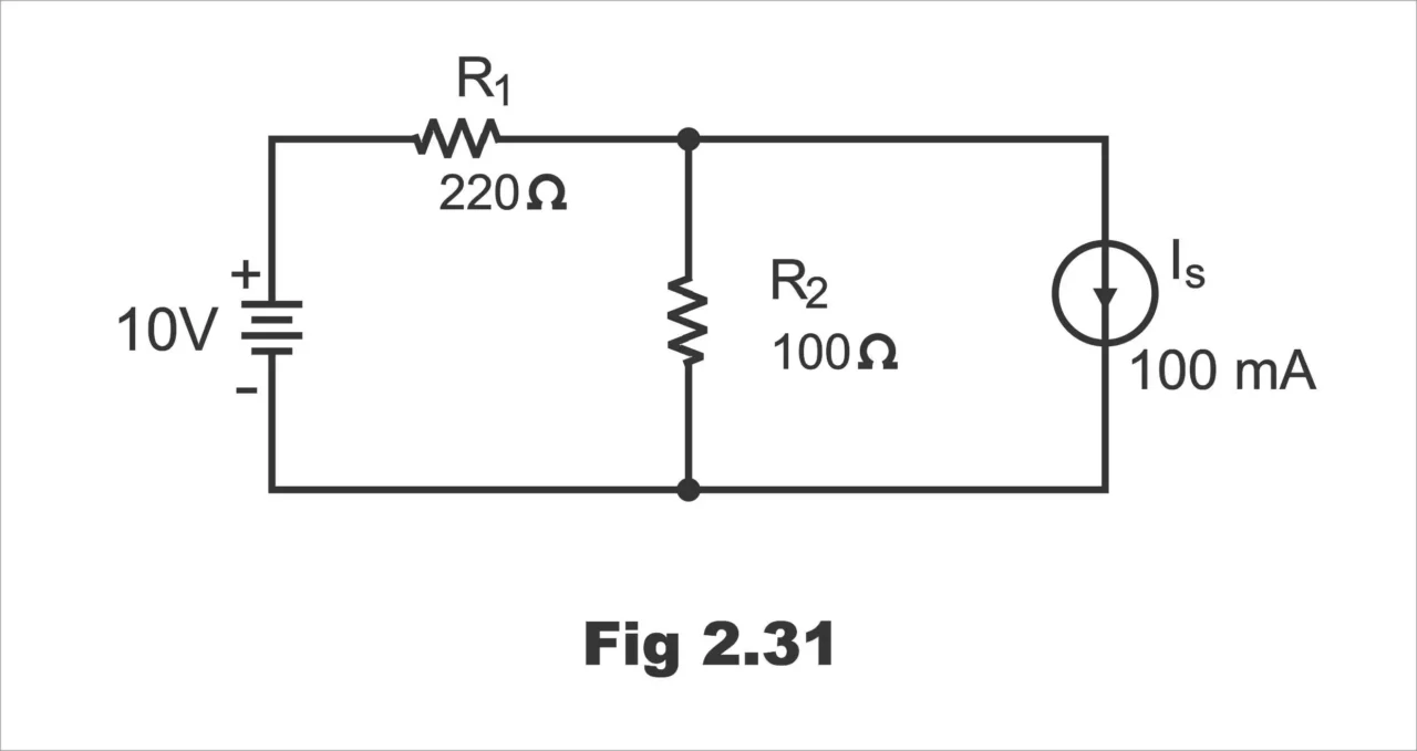
Example 4; Find the current through R2 in the circuit of fig. 2.32
Fig. 2.31
Solution;
First, find the current in R2 due to VS by replacing Is with an open, as shown in figure 2.32. notice that all of the current produced by VS goes through R2.
Figure 2.32
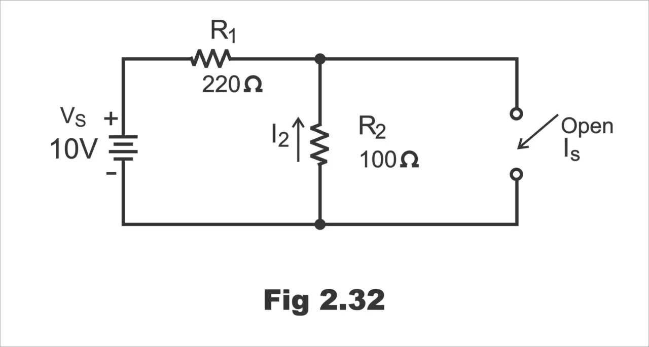
Looking from VS, RT = R1 + r2 = 320 Ω
The current through R2 due to VS is
I2 = VS / RT = 10V / 320 Ω= 0.031 A = 31 mA
Note that this current is upward through R2
Next find the current through R2 due to IS by replacing Vs with a short, as shown in figure 2.33.
Figure 2.33
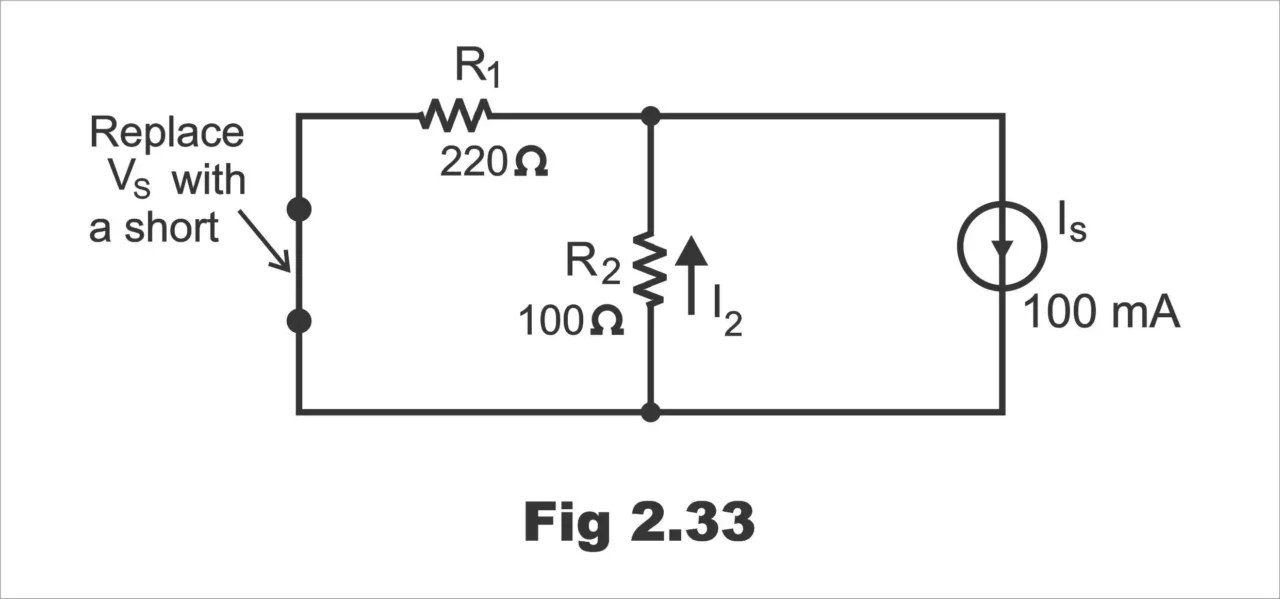
Using the current divider formula, we get the current through R2 due to Is as follows;
I2 = [R1 / R1 + R2] Is = [220 Ω / 320v] 100 mA = 69 mA
Note that this current is upward through R2
Both currents are in the same direction through R2, so we add them to get the total;
I2 (total) = I2 (due to Vs) + I2 (due to Is)
= 31 mA + 69 mA = 100 mA
Example 5; Find the current through the 100 Ω resistor in figure 2.34.
Fig. 2.34
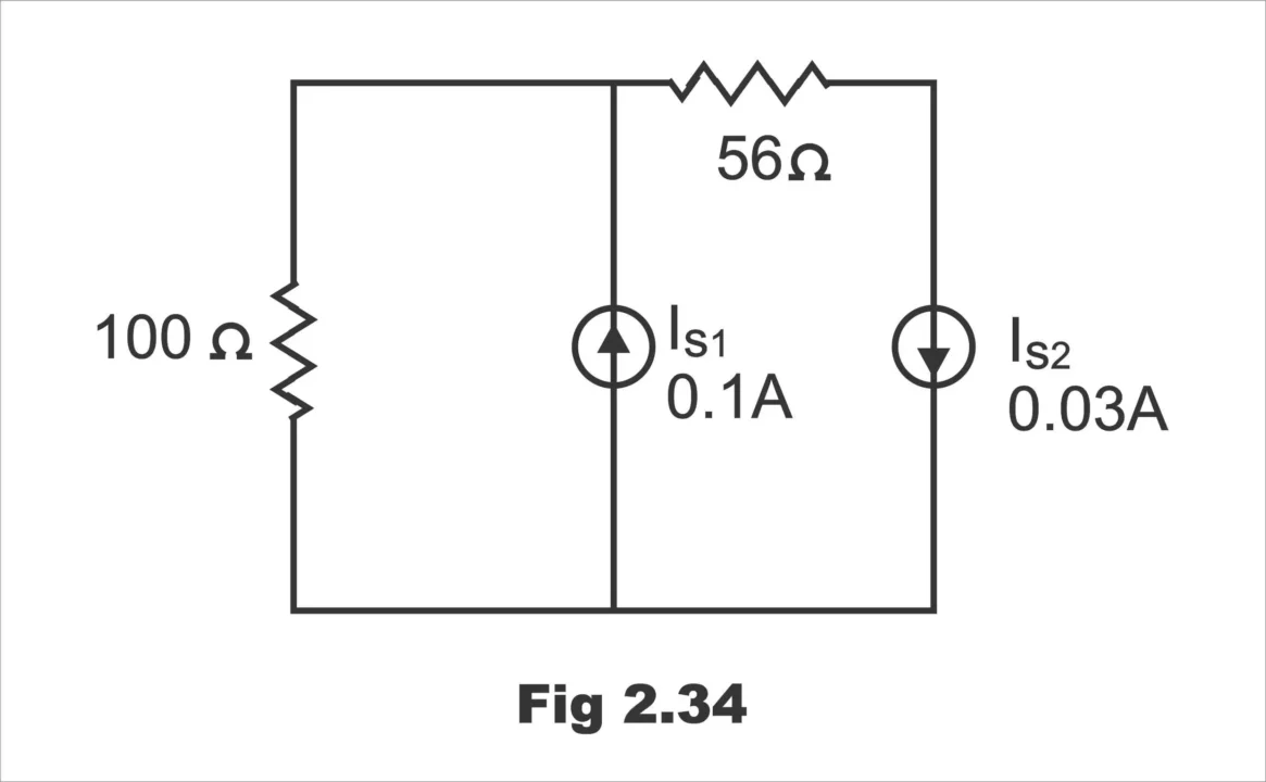
Solution;
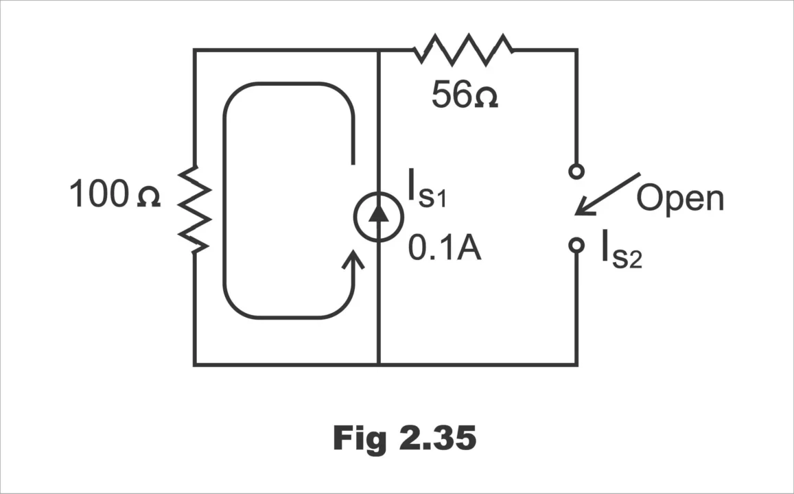
First find the current through the 100 Ω resistor due to current source IS1 by replacing source IS2 with an open, as shown in figure 2.35. As you can see, the entire 0.1 A from the current source IS1 is downward through the 100 Ω resistor.
Fig. 2.35
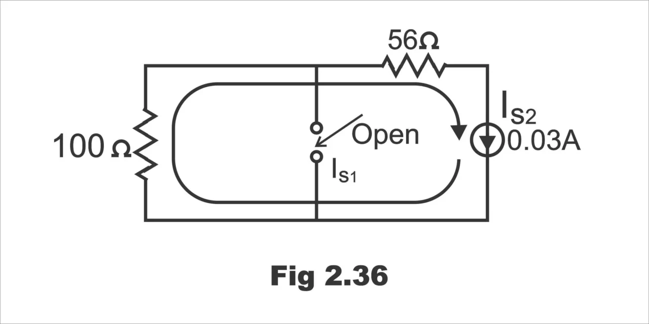
Next find the current through the 100 Ω resistor due to source IS2 by replacing source IS1 with an open, as indicated in figure 2.36. Notice that all of the 0.03 A from source IS2 is upward through the Ω resistor.
Fig. 2.36
To get the total current through the 100 Ω resistor, we subtract the smaller from the larger because they are in opposite directions. The resulting total current flows in the direction of the larger current from source IS1.
I100 Ω (total) = I100 Ω (due to Is1) – I100 Ω (due to IS2)
= 0.1 A – 0.03 A = 0.07 A
The resulting current is downward through the resistor.
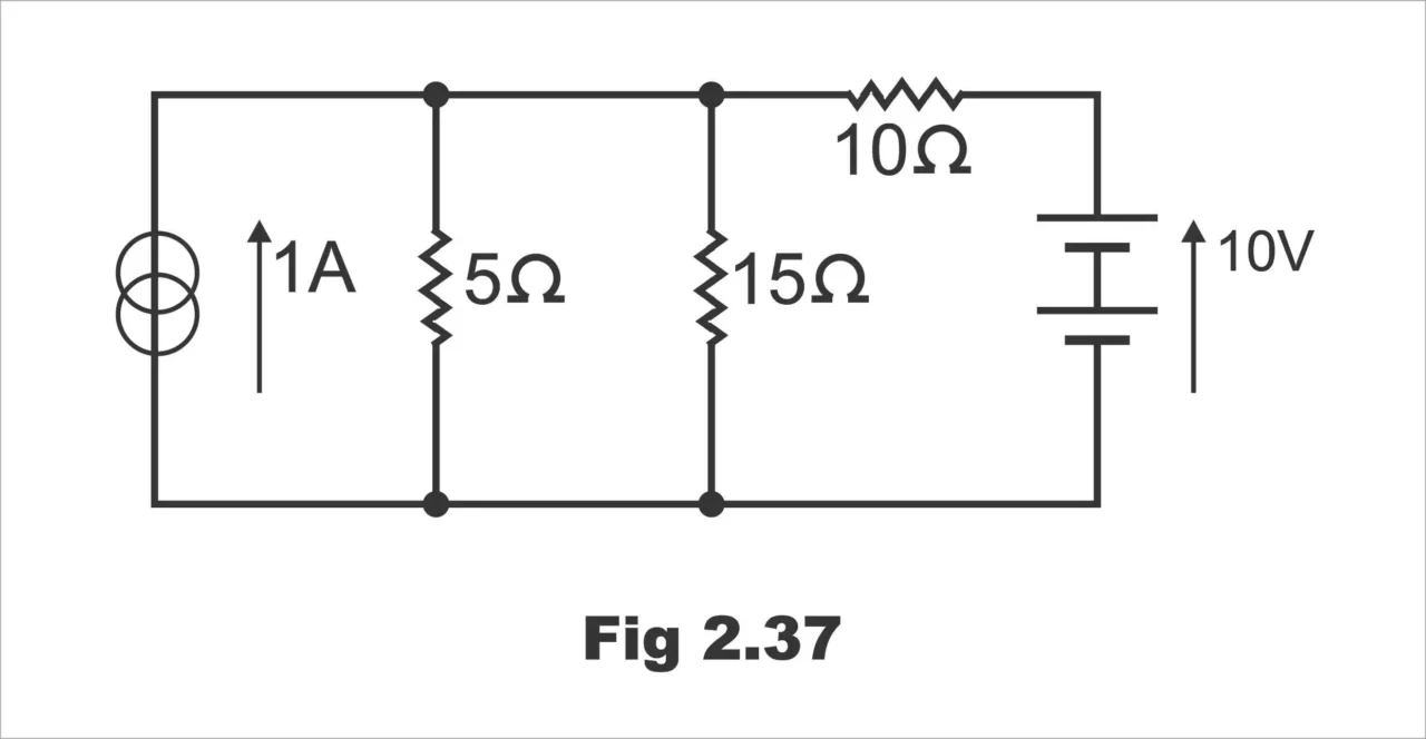
Example 6; Calculate the current in the 15 Ω resistor in the network shown in figure below.
Figure 2.37
Consider the current source alone as shown in figure 2.38.
Figure 2.38
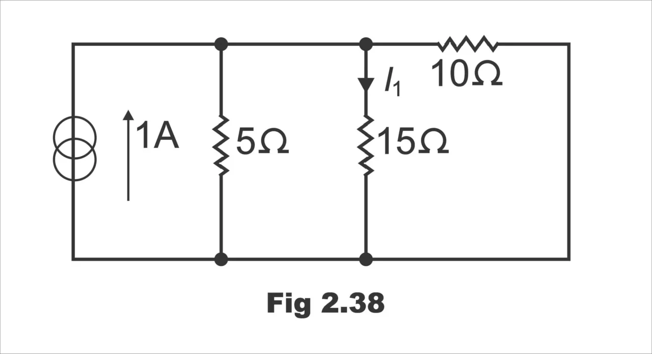
Resistance of 5 Ω in parallel with 10 Ω
= 5 x 10 / 5 + 10 = 3.33 Ω
∴ I1 = 3.33 / 3.33 + 15 x 1 = 0.18 A
Consider the voltage source alone as shown in fig. 2.39
Fig. 2.39
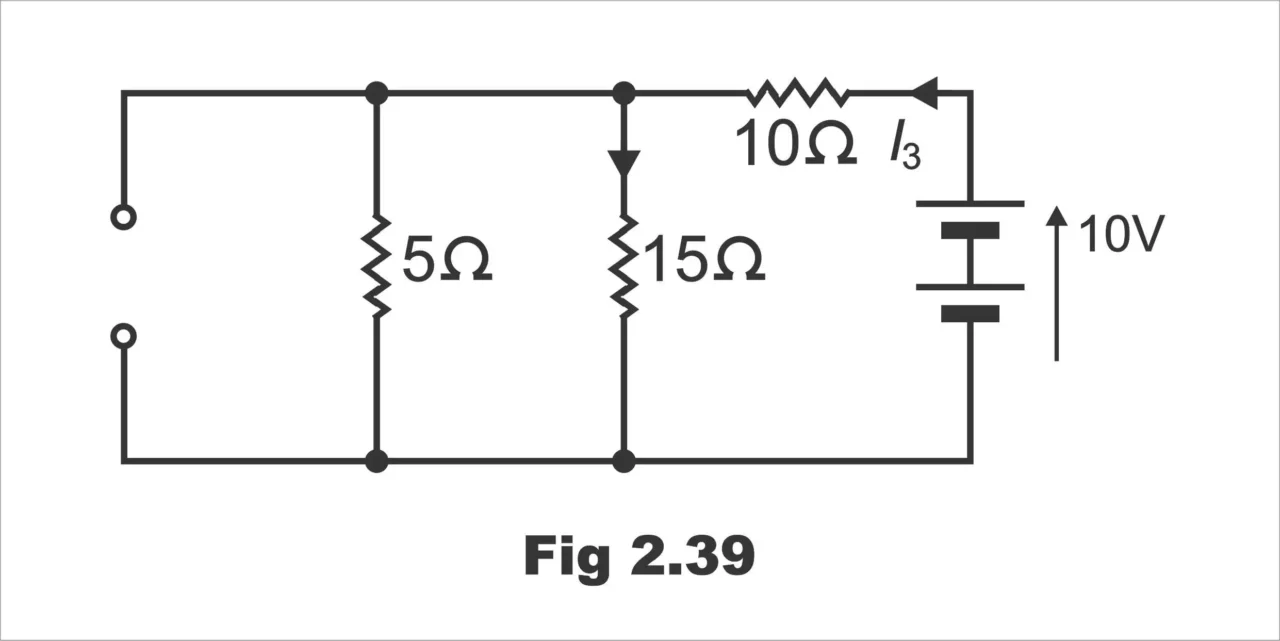
I3 = 10 / 10 + 15 x 5 / 15 + 5 = 10 / 13.75 = 0.73 A
∴ I2 = 5/ 5 + 15 x 0.73 = 0.18 A
∴ Total current in 15 Ω = I1 + I2 = 0.18 + 0.18 = 0.36 A
Example 7: A 4 Ω resistor as shown in fig. below is supplied by two batteries, one of emf 2V and internal resistance 0.1 Ω and other of emf 4V and internal resistance 0.2 Ω. Distribute the currents in the resistors by superposition theorem.
Fig. 2.40
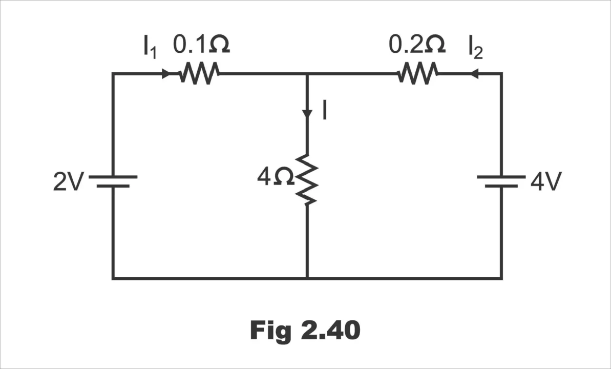
Solution;
The circuit is redrawn in fig. 2.41 (a), when the battery of 4V is short circuited, the total resistance across 2 V battery is;
=0.1 + 0.2 x 4 / 0.2 + 4
Fig. 2.41
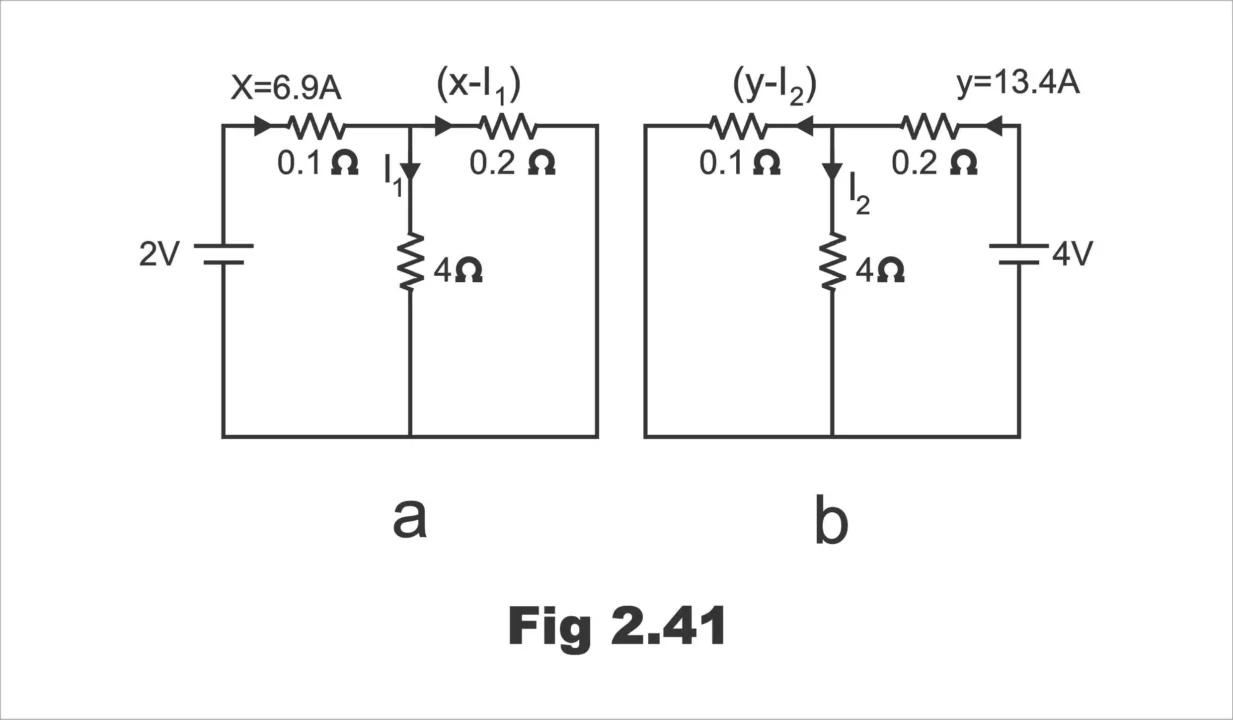
So, the current supplied by 2 V battery, x = 2/ 0.29 = 6.9 A
This gives the current I1 in 4 Ω due to 2 V as 6.9 x 0.19 / 4 = 0.328 A
Again, when 2 V battery is short circuited as shown in fig. 2.41 (b), the total resistance across 4V battery is;
= 0.2 + 0.1 x 4 / 0.1 + 4 = 0.2 + 0.098 = 0.298 Ω
So, the current supplied by 4 V battery, y = 4 / 0.298 = 13.42 A
This gives the current I2 in 4 Ω resistor due to 4V as
= 13.42 x 0.098 / 4 = 0.327 A
Thus, by superposition theorem the current in 4 Ω resistor is
I = I 1 + I 2 = 0.328 + 0.327 = 0.655 A
The current in 0.1 Ω resistor = x – (y – I 2) = 6.9 – (13.42 – 0.327)
= – 0.6193 A
And the current in 0.2 Ω resistor
= y – (x – I 2) = 13. 42 – (6.9 – 0.328)
= + 6.848 A
Example 8; In fig. 2.42 (a) let battery e.m. fs be 6V and 12V, the internal resistances 0.5 Ω and 1 Ω. The values of other resistances are as indicated. Find the different currents flowing in the branches and voltage across 6 Ω resistor.
Solution;
In figure 2.42, (b), 12 – volt battery has been removed though its internal resistance of 1 Ω remains. The various currents can be four by applying ohm’s law;
Figure 2.42
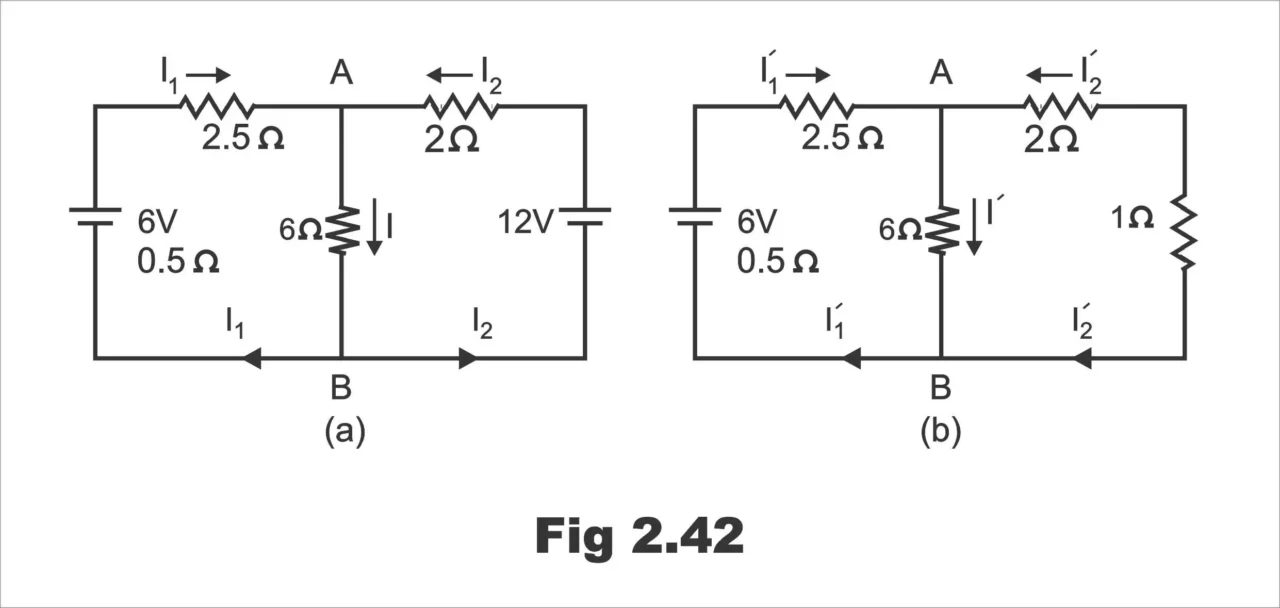
It is seen that there are two parallel paths between points A and B, having resistance of 6 Ω and (2 + 1) = 3 Ω.
∴ equivalent resistance = 3 x 6 / 3 + 6 = 18 / 9 = 2 Ω
Total resistance = 0.5 + 2.5 + 2 = 5 Ω
∴ I’ 1 = 6 / 5 = 1.2
This current divides at point A inversely in the ratio of 1 resistance of the two parallel paths.
∴ I’ = 1.2 x (3/9) = 0.4 A. Similarly, I’ 1 = 1.2 x (6.9) = 0.8
Figure 2.43
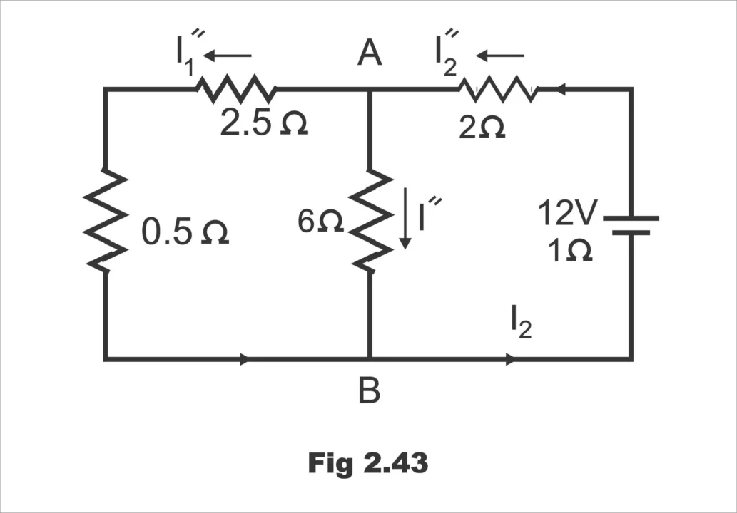
In fig. 2.43, 6 – volt battery has been removed but not its internal resistance. The various currents and their directions are as shown;
The equivalent resistance of the left of points A and b is = 3 x 6 / 3 + 6 = 18 / 9 = 2 Ω
∴ total resistance = 1 + 2 + 2 =5 Ω
∴ I” 2 = 12 / 5 = 2.4 A
At point A, this current is divided into two parts.
I” = 2.4 x 3/9 = 0.8 A and I” 1 = 2.4 x 6/9 = 1.6 A
The actual current values of fig. 2.42 (a) can be obtained by superposition of these two sets of current values.
∴ I 1 = I’ 1 – I” 1 = 1.2 – 1.6 = -0.4 A (it is a charging current)
I 2 = I” 2 – I’ 2 = 2.4 – 0.8 = 1.6 A
I = I’ + I’ = 0.4 + 0.8 = 1.2 A
Voltage drops across 6 Ω resistor = 6 x 1.2 = 7.2 V
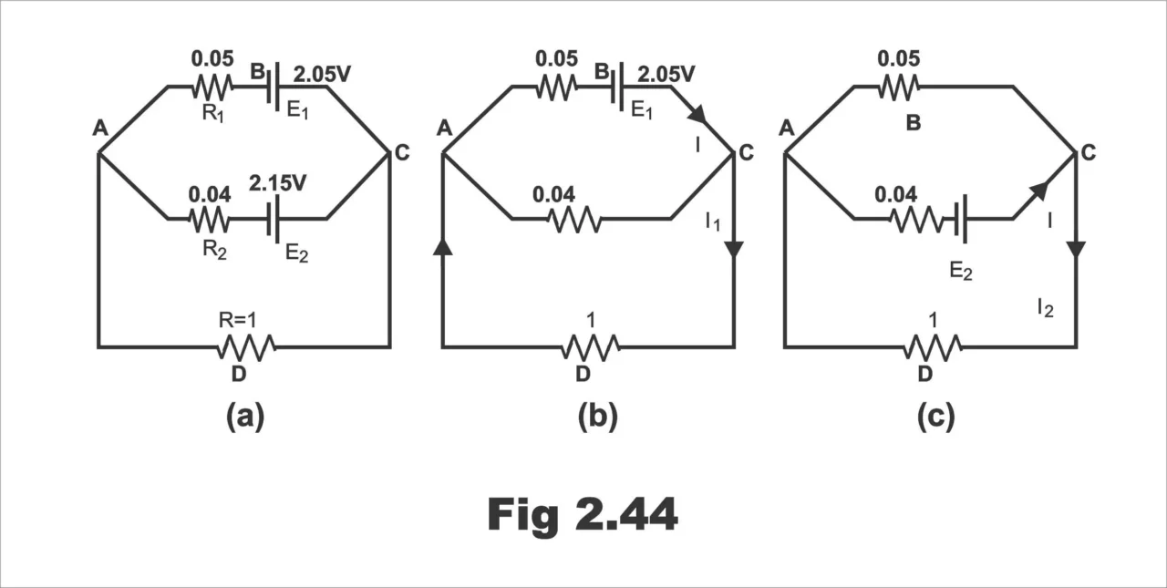
Example 9: By using superposition theorem, find the current in resistance R shown in figure 2.44 (a)
R1 = 0.0 5 Ω R2 = 0.0 4 Ω, R = 1 Ω, E1 = 2.05 V, E2 = 2.15 V
Internal resistances of cells are negligible
Solution;
In fig. 2.44 (b), E2 has been removed. Resistances of 1 Ω and 0.04 Ω are in parallel across points A and C. RAC = 1 x 0.04 / 1 + 0.04 = 1 x 0.04 / 1,04 = 0.038 Ω
This resistance is in series with 0.05 Ω. Hence, total resistance offered to battery E1 = 0.05 + 0.038 = 0.088 Ω. I = 2.05 / 0.088 = 23.3 A
Current through 1 Ω resistance, I1 = 23.3 x 0.04 / 1.04 = 0.896 A, from C to A.
When E1 is removed, circuit becomes as shown in fig. 2.44 ©
Combined resistances of paths CBA and CDA is = 1 x 0.05 / 1 + 0.05 = 1 x 0.05 / 1.05 = 0.048 Ω. Total resistance offered to E2 is = 0.04 + 0.048 = 0.088 Ω
Current I = 2.15 / 0.088 = 24.4 A
Again, I2 = 24.4 x 0.05 / 1.05 = 1.16 A
Figure 2.44
Total current through 1 Ω resistance when both batteries are present
= I1 + I2 = 0.896 + 1.16 = 2.056 A
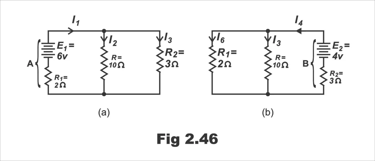
Example 10; Battery A in fig.2.45 has an e.m.f of 6 V and an internal resistance of 2 Ω. The corresponding values for battery B are 4V and 3 Ω respectively. The two batteries are connected in parallel across 1 10 Ω resistor R. Calculate the current in each branch of the network.
Fig. 2.45

Solution;
Fig. 2.46 (a) represents the network with battery A only.
Equivalent resistance of R and R2 in parallel = 10 x 3 / 10 + 3 = 2.31 Ω
∴ I1 = 6 / 2 + 2.31 = 1.392 A
Hence, I2 = 1.392 x 3 / 10 + 3 = 0.321 A
And I3 = 1.392 – 0.321 = 1.071A
Fig. 2.46 (b) represents the network with battery B only.
Equivalent resistance of R and R1 in parallel = 2 x 10 / 2+ 10 = 1.667 Ω
∴ I4 = 4 / 3 + 1.667 = 0.858 A
Hence, I5 = 0.858 x 2 / 2 + 10 = 0.143 A
And I6 = 0.856 – 0.143 = 0.713 A
Fig. 2.46
Superimposing the results for fig. 2.46 (b) on those for fig. 2.46 (a), we have
Resultant current through A = I1 – I6 = 1.392 – 0.713 = 0.679 A
And resultant current through B = I4 – I3 = 0.856 – 1.071 = – 0.215 A
i.e., battery B is being charged at 0.215 A
Resultant current through R = I2 + I5 = 0.321 + 0.143 = 0.464 A
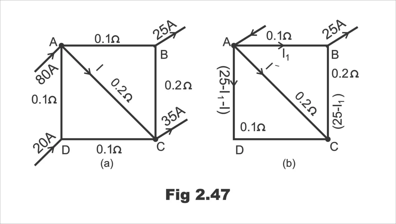
Example 11: A network is composed of the following resistances; AB = 0.1 Ω; BC = 0.2 Ω; CD = 0.1 Ω; DA = 0.1 Ω; AC = 0.2 Ω. A current of 80 A is fed into the network at point A and currents of 25 A, 35 A and 20 A leave at points B, C and D respectively. Applying the superposition theorem, calculate the current in AC.
Solution;
Let the current in AC be I as shown in fig. 2.47 (a). First, consider the 25 A load acting alone. Then, the current distribution is as shown in fig. 2.47 (b).
(i). Applying Kirchhoff’s 2nd law, to loop ABCA, we get
-.1I1 + 0.2 (25 – I1) + 0.2) I’ = 0 or 3I1 – 2I’ = 50 … (i)
Similarly, from loop ACDA, we get
-0.2I’ – 0.2 (25 – I1 -I’) = 0 or I1 + 2I’ = 25 … (ii)
From eq. (i) and (ii) above, we get
I1 = 18.75 A and I’ = 3.125 A
Figure 2.47
(ii) Now let 35 A load act alone. The current distribution is as shown in fig. 2.48 (a)
For loop ABCA; -0.3I’ 1 – 0.2I” = 0 or 3I’ 1 = 2I” … (iii)
For loop ACDA; -0.2 I” + 0.2 (35 – I’ 1 – I”) = 0 or I’ 1 + 2I” = 35 … (iv)
From eq. (iii) and (iv), we get
I” 1 = 8.75 A; I” = 13.125 A
(iii). Finally, connecting the 20 A load to act alone [fig. 2.48 (b)], we have
Fig. 2.48
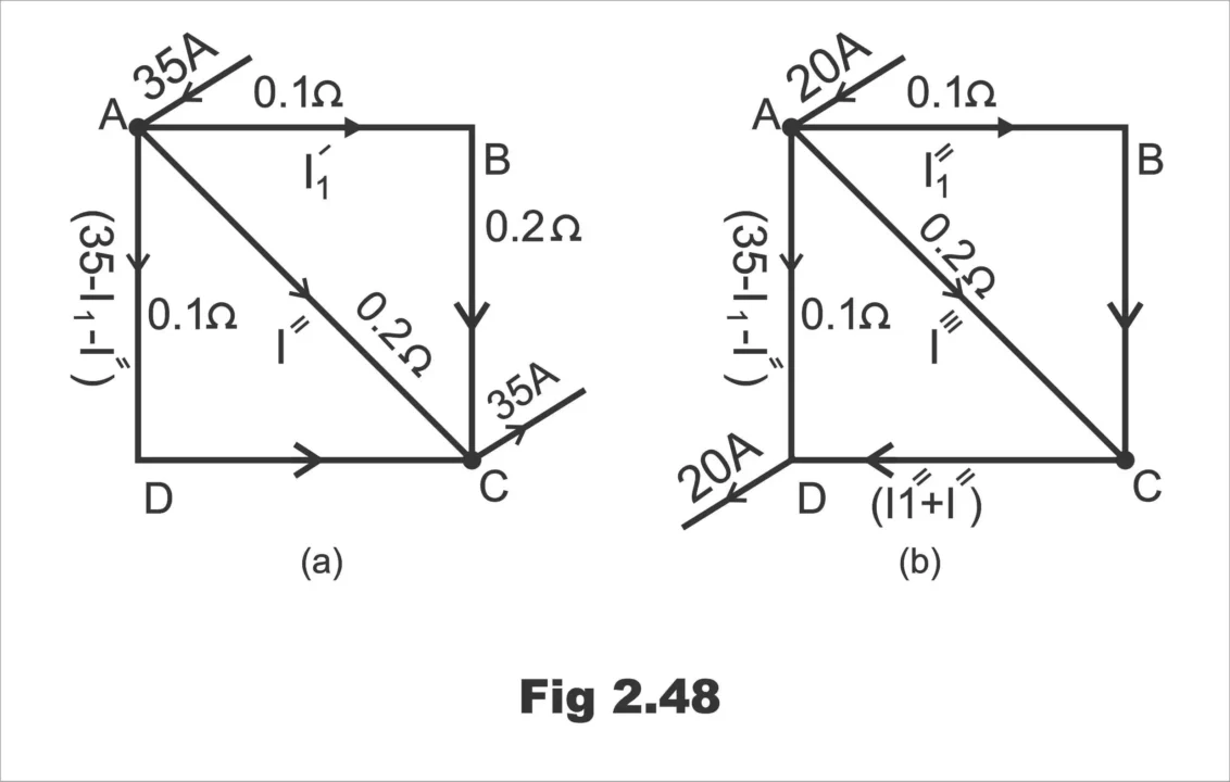
For loop ABCA; 0.3I” 1 + 0.2I” = 0 or 3I” 1 = 2 I”’ … (v)
For loop ACDA; -0.2I”’ – 0.1 (I” + I”’) + 0.1 (20 – I” 1 – I”’) = 0 or I 1” + 2 I’” = 10 … (vi)
From eq. (v), and (vi), we get
I1” = 2.5 A; I”’ = 3.75 A
According to the superposition theorem, the total current in branch AC due to all the loads acting simultaneously is;
I = I’ + I” + I”’ = 3.125 + 13.125 + 3.75 = 20 A … from A to C
Frequently Asked Questions – FAQs
Question1 What is the superposition theorem?
Superposition means a method through which a circuit is resolved at a time under the effect of just one out of several energy sources installed on the circuit and then adding up the effects of all these sources ultimately.
Question2 Can the superposition theorem be applied to non-linear circuits?
No, superposition theorem is only used in linear networks, where the relation between current and voltages tend to be directly proportional under the ohm’s law.
Next Topic: Maximum Power Transfer Theorem with Solved Examples
Previous Topic: Kirchhoff’s Current & Voltage Law with Solved Examples
Discover more from Electronic Clinic
Subscribe to get the latest posts sent to your email.