Deep Sleep Modes in ESP32 and how to use them
Table of Contents
Deep Sleep modes in the ESP32:
Deep Sleep Mode in ESP32– This article is going to be very helpful for you guys if you plan to make a battery operated monitoring and control system using ESP32. You won’t want your battery to discharge in hours or in a few days. You can use the ESP32 Sleep Modes to save power. The ESP32 is a very powerful microcontroller board developed by Espressif Systems with a fast processor, a lot of memory, and with built-in WiFi and Bluetooth, surely that must mean that it’s not suitable for battery operation. Well, actually know the ESP32 can run on batteries for a long time if you carefully manage how long you used the CPU and WiFi. In a nutshell you want to keep the processor in a sleep mode for as long as possible and when you actually need to power on the CPU do it as shortly as possible. The same thing goes for WiFi, turn it on only when you have to and for as little long as possible. Additionally the ESP32 supports various power modes. Let’s go over them right now and to make it easier to understand I have visualized the components inside the ESP32.
Related Article:
Active Sleep:
The heaviest power mode is called active. In this mode the processor is turned on as well as the WiFi and Bluetooth radio. This comes with a power consumption of up to 260 milliamps which could deplete a 2000 million power battery in just under 8 hours. However you do not need WiFi and Bluetooth to be on all the time. If you turn them off the chip switches to modem sleep. This reduces the power consumption to 20 milliamps and you can still use the full power of the processor and if you reduce the clock speed of the processor you can get that down to as low as 3 milliamps not bad but still nowhere near good enough.
Light Sleep:
In this state the main processor is paused and is waiting for events to wake it up. This can be a timer or an external interrupt like the press of a button. In this state the contents of the memory will be retained when the CPU wakes up. Power consumption of light sleep is around 0.8 milliamps. To reduce that even further, you can go into deep sleep, a mode in which the processor and most of the peripheral are turned off to conserve power. The chip can still wake up from external interrupts because the ULP the ultra-lowpower processor is still turned on. Power consumption at this stage is 0.15milliamps, further reduction of power consumption can be achieved by turning the ULP off and only keeping the RTC timer and memory on. This results in a power consumption of just 10 micro amps.
Hibernation:
The final power mode is hibernation, which turns off everything except the RTC timer that way the chip can still wake up after a certain amount of time but no memory is kept powered on. So you can’t preserve data. During hibernation, power consumption here is just 5 micro amps. So, in short deep sleep hibernation is the way to go if you want to preserve battery life but that means you have to get creative, how can you sleep as long as possible and use the Wi-Fi as little as possible.
Now we will discuss how to put the ESP32 in deep sleep mode. We will try to put our ESP32 into deep sleep and check whether our ESP32 is consuming less battery or not. For this tutorial, I am using the Sparkfun ESP32 thing, if you are using another ESP32 well don’t worry the code is the same for every ESP32. However some ESP32 do seem to have a problem when they are in deep sleep and still consume a lot of battery. We will be doing three things that will be useful for you or we can make the ESP32 in deep sleep mode using three methods:
In the first method once your ESP32 is in sleep deep sleep you might want to save some data that you don’t want to get lost. We will solve this by using our RTC memory.
In the second method, we will set a timer for when the ESP32 can access deep sleep
In the third method, we will use a GPI open or touch pins that you can use or touch to make the ESP32 exit deep sleep or when pressing a button
This is all very helpful stuff for your projects. Before discussing these methods in detail we will briefly describe the interfacing of the ESP32 with the Arduino IDE. We have described it in detail in previous articles. Now in order to use ESP32 in Arduino IDE we have two methods to install the ESP32 board in the Arduino IDE.
First method of installing the ESP 32 Module to the Arduino IDE:
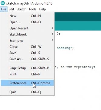
In the first method open the Arduino ide and in file click on the preference
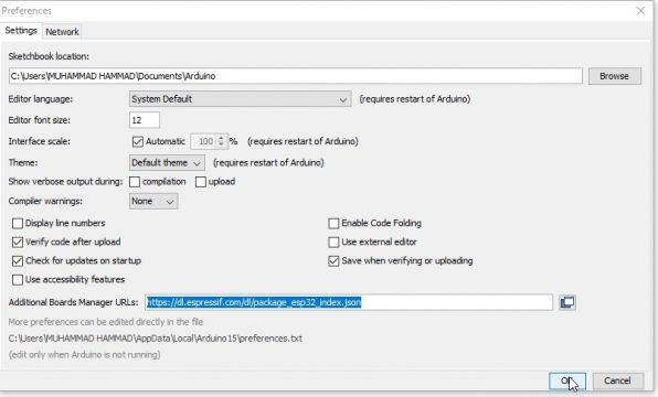
When the preference will open paste the link and click on ok.
https://dl.espressif.com/dl/package_esp32_index.json
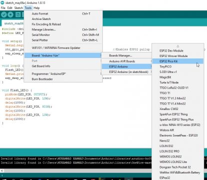
Now in the tools go to the board manager
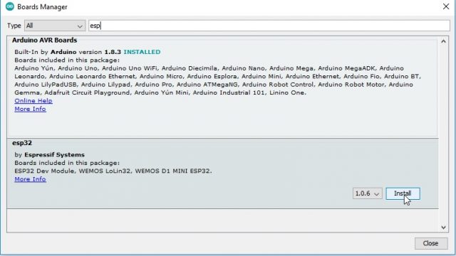
In the board manager search for the ESP32 and click on install button
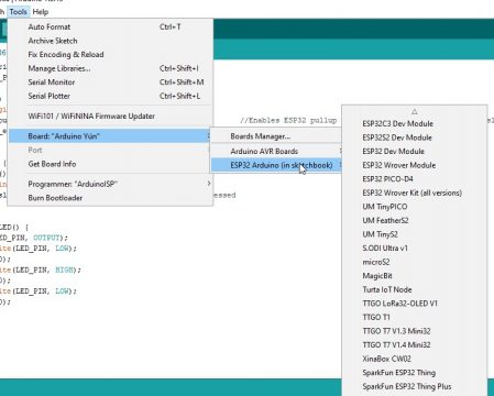
After the installation is completed we can select the ESP32 board.
Second method of installing the ESP32 Module to the Arduino IDE:
we will first download the git GUI (graphical user interface) from the given link:
After downloading open the Git software and install it by clicking the next:
Now another dialog box will appear where we want to save the software.
In the next step we will select the component to install
Now by just clicking the next options installing will be started. After the completion of the installation open the gitgui.
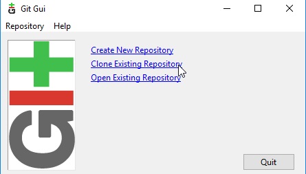
Now after opening the git gui click on the clone existing repository
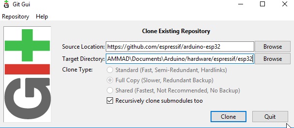
Now in the source location we will paste the link:
https://github.com/espressif/arduino-esp32
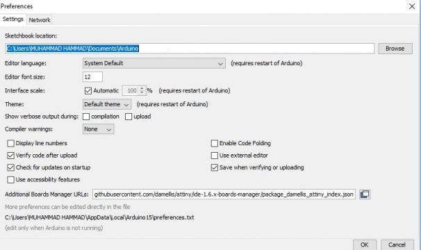
For the target directory we will first open the arduino UNO go to file and select the preference.
In the preference we will copy the target location:
Now paste that location in the git and also write the following command after the arduino
\Arduino/hardware/espressif/esp32
After clicking on the clone the process will start and after the setup is completed open the Arduino ide and you can see that the ESP32 board is installed.
RTC memory:
|
1 2 3 4 5 6 7 8 9 10 11 12 13 14 15 16 17 18 19 20 21 22 23 24 25 26 27 28 |
Code: RTC_DATA_ATTR int counter = 0; void setup() { Serial.begin (115200); Serial.println ("the ESP 32 booting"); ++counter; pinMode (5,OUTPUT); delay (500); digitalWrite (5, HIGH); delay (2000); for (int i=0; i<= counter; i++ ) { digitalWrite (5, LOW); delay (200); digitalWrite (5, HIGH); delay (200); //sleep time in microseconds esp_sleep_enable_timer_wakeup (3000000); esp_deep_sleep_start(); } } void loop() { // put your main code here, to run repeatedly: } |
Code Explanation:
Open up the Arduino and create an integer that we can use as our RTC memory. Now that we have created the integer counter.
int counter = 0;
We want to send it to the RTC memory we do this by adding this in front of the integer
RTC_DATA_ATTR int counter = 0;
This marks the integer as RTCmemory meaning everything you save in this integer will be remembered whenever the ESP32 comes out of its deep sleepState.
Setup ():
In the setup function we will first start serial communication by writing the command:
Serial.begin (115200);
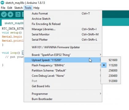
The same number as you are uploading speed you can check this by clicking on tools and then check the uploading speed here it says 115200 like in my code.
After that we will display that the ESP32 is booting by writing the command
Serial.println (“the ESP 32 booting”)
We are going to up our counter by 1 this means the number 1 will be added to the counter. Why I am doing this will get clearer soon.
++counter;
After this we want to set the pin number 5 to output for the spark for the ESP32 this is the standard built-in LED. So make sure you choose the correct pin for your ESP32 or connect an LED to the pin.
pinMode (5,OUTPUT);
Now add a delay this is needed because otherwise a weird glitch happens with the LED after a while but this may not happen for you, after this we want to turn on our LED and wait for another 2 seconds this is to make clear that the ESP32 is ON.
delay (500);
digitalWrite (5, HIGH);
delay (2000);
Now we are going to write a short for loop where we will be using our counter as the max number I have set this to the counter so that every time the ESP32 comes back out of deep sleep it will run the void setup again meaning the ++counter part right over here will be hit over and over again.
So every time the ESP32 leaves deep sleep it form before loop will be under more and more. Now to make clear how many times the counter will be added up we will make the LED go off and on every time before loop is hit so add this to the for loop.
|
1 2 3 4 5 6 7 8 |
for (int i=0; i<= counter; i++ ) { digitalWrite (5, LOW); delay (200); digitalWrite (5, HIGH); delay (200); } |
Now every time the ESP32 boots, the LED will turn off and on, one more time this will prove that the RTC memory is actually working. Now after the for loop is done we will just add in one more delay of 2 seconds.
Now we will set a timer for how many seconds are ESP32 can stay in deep sleep after this passes the ESP32 will boot up again.
esp_sleep_enable_timer_wakeup (3000000);
Now notice that the number is quite high this is because the value that the time-resolved has to be in microseconds so meaning six zeros and a number three in front, for example we will create at imer of three seconds. Now to actually put our ESP32 into deep sleep we add this line
esp_deep_sleep_start();
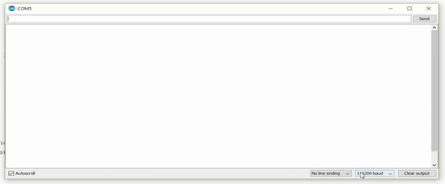
Now I will test this and check if theESP 32 actually uses less power after that we will try to put up the ESP32 by simply touching a pin which could be very interesting in your future projects and open up the serial monitor by pressing tools and then serial monitor and make sure this has a 115200 baud.
And as you can see the ESP32 is going into deep sleep and booting every time and every time it does the LED flashes one time then it off and after 5 seconds it will again turn on.
Deep sleep mode using touchpad:
Now let’s make the ESP32 to boot again by not only the timer but by touching a pin and once it does get rewarded by touching the pin it will reset our RTC memory to make sure it actually works when hooked up to the battery. Now we will add several lines in the setup before setting the timer to 3 seconds. This will make sure the GPIO pin15 will be listening for a touch and enables the touchpad as any wakeup source.
code:
|
1 2 3 4 5 6 7 8 9 10 11 12 13 14 15 16 17 18 19 20 21 22 23 24 25 26 27 28 29 30 31 32 33 34 35 36 37 38 39 40 41 42 43 44 45 46 47 48 |
RTC_DATA_ATTR int counter = 0; #define threshold 40 void callback() { } void setup() { Serial.begin (115200); Serial.println ("the ESP 32 booting"); ++counter; pinMode (5,OUTPUT); delay (500); digitalWrite (5, HIGH); delay (2000); esp_sleep_wakeup_cause_t wakeup_reason; wakeup_reason = esp_sleep_get_wakeup_cause(); if (ESP_SLEEP_WAKEUP_TOUCHPAD == wakeup_reason ) { counter=0; Serial.println("reset"); } for (int i=0; i<= counter; i++ ) { digitalWrite (5, LOW); delay (200); digitalWrite (5, HIGH); delay (200); } delay (2000); //setup interrup on touch pad 3 (GPIO 15) touchAttachInterrupt (T3, callback, threshold); //configure touchpad as wakeup source esp_sleep_enable_touchpad_wakeup (); //sleep time in microseconds esp_sleep_enable_timer_wakeup (3000000); esp_deep_sleep_start(); } void loop() { // put your main code here, to run repeatedly: } |
|
1 |
LaunchAttachInterrupt (T3, callback, threshold); |
Now the first value there is the T3 pin so the touchpad pen or GPIO 15. Now the second value will be calling for which we will define the function callback. This is not used yet but in case if we need then it will be used.
|
1 2 3 4 5 6 7 8 |
void callback() { } |
The last is threshold is actually the value you have to define or do this for the sensitivity of the pin the greater the value the more sensitivity. So go all the way up and define this value like so now that this is done we go back to our for loop and above the for loop we will add two lines
|
1 2 3 |
esp_sleep_wakeup_cause_twakeup_reason; wakeup_reason = esp_sleep_get_wakeup_cause() |
This enables us to get the cause of the ESP32 to access exiting deep sleep now let’s write an if statement and if the wake up TouchPad equals to the wake up reason then we will set the counter to zero like so:
|
1 2 3 4 5 6 7 8 9 |
if (ESP_SLEEP_WAKEUP_TOUCHPAD == wakeup_reason ) { counter=0; Serial.println("reset"); } |
Now let’s run this code the counter keeps on going up now let’s reset the counter by touching GPIO pin 15 and when we touch the GPIO pin LED only flashes once.

