E-Ink Display Feels Like Real Paper: Here is Why It Matters
Explore the Benefits of E-Ink Displays: From Sunlight Readability to Ultra-Low Power
Last Updated on August 24, 2025 by Engr. Shahzada Fahad
Table of Contents
Description:
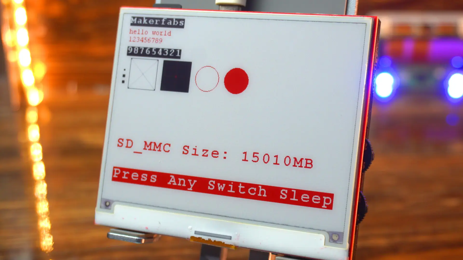
Today, I have got something really exciting on my desk; the MaTouch ESP32-S3 with a 4.2-inch triple-color E-Ink display.

This is not your everyday screen. Unlike LCDs or OLEDs, this display works just like printed paper.
To really put this E-Ink display to the test, I placed it side by side with an actual sheet of paper. I wanted to see if it truly behaves like paper in every way. So, I switched off the room light… and I was completely shocked
What is E-Ink Technology?
An E-Ink display is a special type of screen that looks very similar to real paper.
Unlike the bright backlit screens on phones or laptops, an E-Ink display works in a special way. Inside the screen are millions of microcapsules filled with charged particles. In a traditional black-and-white E-Ink display, you only get black and white particles. But in this tri-color E-Ink display, there are also red particles.
When an electric charge is applied, these particles move to the surface of the screen to form text and images. That’s why you can see white, black, and red colors on this display; without needing a backlight.
These particles move around with the help of electric charges to form letters and images.
Because of this unique design, an E-Ink display (also known as an Electronic Paper Display or E-Paper Display) does not shine light directly into your eyes.
Instead, it reflects light from your surroundings; just like paper does.
That’s why reading on a paper-like display feels comfortable, even for long hours, unlike the harsh glow of traditional backlit screens.
In this article, I will take you through the hardware, the digital paper screen specs, and its features. We will also test it with some cool examples to see how it performs in real projects.
So; if you are into low-power displays, want a sunlight-readable display, or are curious about Kindle screen technology and E-paper technology, then stick around. This one is going to be fun!
So, without any further delay let’s get started!!!
Amazon Links:
Other Tools and Components:
ESP32 WiFi + Bluetooth Module (Recommended)
Arduino Nano USB C type (Recommended)
*Please Note: These are affiliate links. I may make a commission if you buy the components through these links. I would appreciate your support in this way!
E-Ink Display Features:

Now let’s take a closer look at the board itself and go through the different interfaces.
Up here, we have the I2C connector, which is useful if I want to connect external sensors or expansion modules that use the I2C protocol.

Next to it is the GPIO header. This gives me access to general-purpose pins from the ESP32-S3, so I can connect LEDs, relays, or other peripherals.
Then, we have got two USB ports: USB-TTL and USB-Native. The USB-TTL is mainly for programming and debugging through serial communication, while the USB-Native can be used for direct USB functions, since the ESP32-S3 supports native USB.
Right beside that, there is the battery connector. You can plug in a Li-Po battery here to make the board portable, which is really handy for low-power E-Ink projects.
On the right side, we have the SD card slot. This allows us to store images, fonts, or other large data files that can be displayed on the E-Ink screen.
At the center, of course, is the ESP32-S3 chip, the brain of this board. It’s a dual-core microcontroller with Wi-Fi and Bluetooth built-in, and it’s powerful enough to handle graphics and wireless communication at the same time.
Down here, we have two buttons: SW1 and SW2. These are user-programmable, so we can assign them to any function we like; for example, refreshing the screen or changing the display mode. Or we can use it to activate and deactivate the sleep mode.
At the bottom, there are also the Flash and Reset buttons. Reset simply restarts the board, while Flash is used for putting the ESP32 into programming mode if needed.
And finally, we have the SPI interface for the E-Ink display connection. This is the high-speed communication channel between the ESP32-S3 and the display itself.
So overall, the board gives me a lot of flexibility with multiple power options, external interfaces, and enough connectivity to build serious projects.
E-Ink Display Features:
- ESP32-S3 E-Ink Display Board Specifications
- Controller: ESP32-S3
- Wireless Connectivity: Wi-Fi & Bluetooth 5.0
- Flash Memory: 16MB
- PSRAM: 8MB
- Expansion Interface: 1 × GPIO, 1 × I²C
- MicroSD Card Slot: Yes
- Buttons: Flash button & Reset button
- USB Ports: 1 × USB to UART, 1 × USB Native
- Input Voltage: 3.7V Battery or 5V Type-C
- Arduino Support: Yes
One interesting thing is that a full refresh takes about 15 seconds, but the big advantage is super low power consumption; once the image is on the screen, it stays there without using almost any power.
And here’s the part that really blew my mind; Even after I disconnected the power, the image on the display was still clearly visible.

That’s the beauty of E-Ink technology; it doesn’t need constant power to keep the image on screen.
Of course, if you are using this board with sensors or other peripherals, then you wil need to keep it powered with a battery. But for just displaying information, this feature is absolutely amazing. It makes the display super energy efficient and perfect for low-power projects.
E Ink Display LCD Specs:
- Part Number: GDEH042Z21
- Size: 4.2 inch
- Resolution: 400 × 300
- Type: Dot Matrix
- IC Driver: UC8276
- Max Grayscale: 2
- Color: Black, White, Red
Dimensions:
- Outline Size (mm): 91 × 77 × 1.25
- Active Area (mm): 84.8 × 63.6
- Pixel Pitch (mm): 0.212 × 0.212
- Connector: 24 Pin FPC
Performance:
- Interface: SPI
- Full Refresh Time (s): 15
- Power Consumption (Refresh, mW): 8.91
- Standby Power Consumption (mW): 0.0056
Environment:
- Operating Temperature: 0°C ~ 40°C
- Storage Temperature: -25°C ~ 60°C
Download ESP32-S3 E-Paper Examples from GitHub
After this, you can head over to MakerFab’s official GitHub repository. Just make sure you see ESP32S3_4.2_EINK and download the entire ZIP package.
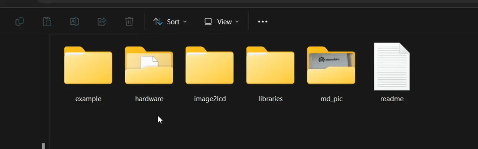
Inside this folder, you will find everything you need for this project.
- In the Example folder, there are four ready-to-use examples, which we will be testing in a moment.
- In the Hardware folder, you even get the original PCB design file, schematic, and PDFs.
It’s completely open source; and that’s one of the reasons I really like MakerFab. They provide everything to their users, so you are not left guessing or stuck without resources.
- To make things easier, they have also provided a little tool called Image2Lcd. With this software, you can convert any picture or text into the right format for the E-Ink display. Basically, you load your image, adjust the settings, and it gives you the byte array that you can use directly in your code.
If you like designing your own graphics, you can create images in Photoshop or any other photo editor, save them, and then either convert them with the Image2Lcd software or just copy them straight to the SD card. That way, you get full control over how your images look on the display. I will practically show this to you.
- In the Libraries folder, we also get the ESP32-waveshare-epd library. This one isn’t pre-installed in Arduino, so we will need to add it manually. Let’s go ahead and do that now.
Open the Arduino IDE, go to Sketch > Include Library > Add .ZIP Library, and then select the library zip folder.

As you can see I have already installed this library so I am going to click on the NO Button.

About the Arduino IDE and ESP32:
Before we start, let me quickly share my software setup.

Right now, I am using Arduino IDE version 2.3.4 and the ESP32 board package version 2.0.11. All of my recent touch display projects have been done with the same versions, and they have worked smoothly. So, if you want to follow along without running into errors, I recommend using the same setup.
Now let’s go ahead and test all four examples one by one, so you can see how this display actually performs. And once we are done with these, we will also create our own simple interface in Photoshop, just to display a numeric value on the screen. That way, you will see how easy it is to design your own custom graphics and push them to the display.
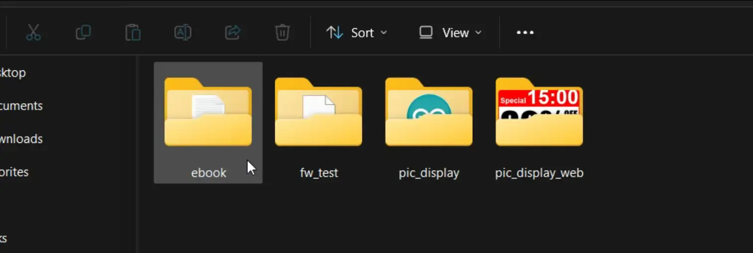
Anyways, let’s now open the Ebook example folder. Inside this folder, you will find the main Arduino .ino file along with a simple text file.
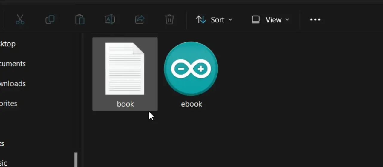
You can write anything you want inside this text file; whatever you type in this txt file be printed on the E-Ink display.
Once you are done writing, just copy this file and paste it onto the SD card.
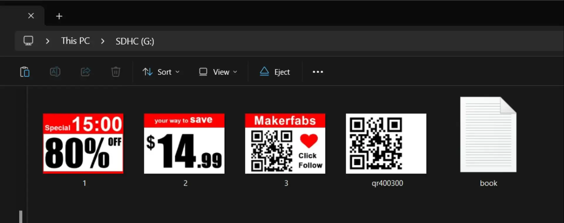
Some of the examples also use images, and to save time I have already copied those images onto the SD card as well.
Now, let’s insert the SD card into the slot, connect the E-Ink display to the laptop, and open up the Ebook Arduino file to get started.
E Ink Display “Ebook example”:
|
1 2 3 4 5 6 7 8 9 10 11 12 13 14 15 16 17 18 19 20 21 22 23 24 25 26 27 28 29 30 31 32 33 34 35 36 37 38 39 40 41 42 43 44 45 46 47 48 49 50 51 52 53 54 55 56 57 58 59 60 61 62 63 64 65 66 67 68 69 70 71 72 73 74 75 76 77 78 79 80 81 82 83 84 85 86 87 88 89 90 91 92 93 94 95 96 97 98 99 100 101 102 103 104 105 106 107 108 109 110 111 112 113 114 115 116 117 118 119 120 121 122 123 124 125 126 127 128 129 130 131 132 133 134 135 136 137 138 139 140 141 142 143 144 145 146 147 148 149 150 151 152 153 154 155 156 157 158 159 160 161 162 163 164 165 166 167 168 169 170 171 172 173 174 |
#include "DEV_Config.h" #include "EPD.h" #include "GUI_Paint.h" #include <stdlib.h> #include "FS.h" #include "SD_MMC.h" extern const unsigned char gImage_black[]; extern const unsigned char gImage_red[]; #define BUTTON_PIN 12 #define PIN_SD_CMD 2 #define PIN_SD_CLK 42 #define PIN_SD_D0 41 #define FILE_NAME "/book.txt" uint64_t cardSize = 0; UBYTE *BlackImage, *RYImage; // Red or Yellow File file; int page_num = 1; void setup() { USBSerial.begin(115200); USBSerial.println("EPD_4IN2B_V2_test Demo\r\n"); DEV_Module_Init(); pinMode(BUTTON_PIN, INPUT); SD_MMC.setPins(PIN_SD_CLK, PIN_SD_CMD, PIN_SD_D0); if (!SD_MMC.begin("/sdcard", true, true)) { USBSerial.println("Card Mount Failed"); while (1) delay(100); } USBSerial.println("e-Paper Init and Clear...\r\n"); EPD_4IN2B_V2_Init(); EPD_4IN2B_V2_Clear(); DEV_Delay_ms(500); // Create a new image cache named IMAGE_BW and fill it with white UWORD Imagesize = ((EPD_4IN2B_V2_WIDTH % 8 == 0) ? (EPD_4IN2B_V2_WIDTH / 8) : (EPD_4IN2B_V2_WIDTH / 8 + 1)) * EPD_4IN2B_V2_HEIGHT; if ((BlackImage = (UBYTE *)malloc(Imagesize)) == NULL) { USBSerial.println("Failed to apply for black memory...\r\n"); while (1) ; } if ((RYImage = (UBYTE *)malloc(Imagesize)) == NULL) { USBSerial.println("Failed to apply for red memory...\r\n"); while (1) ; } USBSerial.println("NewImage:BlackImage and RYImage\r\n"); Paint_NewImage(BlackImage, EPD_4IN2B_V2_WIDTH, EPD_4IN2B_V2_HEIGHT, 0, WHITE); Paint_NewImage(RYImage, EPD_4IN2B_V2_WIDTH, EPD_4IN2B_V2_HEIGHT, 0, WHITE); // Select Image Paint_SelectImage(BlackImage); Paint_Clear(WHITE); Paint_SelectImage(RYImage); Paint_Clear(WHITE); file = SD_MMC.open(FILE_NAME); display_page(); while (1) { if (digitalRead(BUTTON_PIN) == 0) { delay(100); if (digitalRead(BUTTON_PIN) == 0) { long button_time = millis(); while (1) { if (digitalRead(BUTTON_PIN) == 1) break; delay(500); } if ((millis() - button_time) < 3000) { // Job display_page(); } else break; } } } file.close(); USBSerial.println("Clear...\r\n"); EPD_4IN2B_V2_Clear(); USBSerial.println("Goto Sleep...\r\n"); EPD_4IN2B_V2_Sleep(); free(BlackImage); free(RYImage); BlackImage = NULL; RYImage = NULL; } /* The main loop -------------------------------------------------------------*/ void loop() { } int read_line(File &file, char *line, int length) { int c = 0; int i = 0; while (file.available()) { c = file.read(); if (c == '\r') continue; else if (c == '\n') { break; } else { line[i++] = c; } if (i >= length - 1) break; } line[i] = '\0'; return i + 1; } void display_page() { char txt[12][30]; USBSerial.println("New page\n"); Paint_SelectImage(BlackImage); Paint_Clear(WHITE); if (!file) { USBSerial.println("Failed to open file for reading"); return; } Paint_DrawString_EN(20, 0, FILE_NAME, &Font24, BLACK, WHITE); char temp[30]; sprintf(temp,"Page :%04d ",page_num++); USBSerial.println(temp); Paint_DrawString_EN(20, 280, temp, &Font16, BLACK, WHITE); for (int i = 0; i < 12; i++) { int c_cont = 0; c_cont = read_line(file, txt[i], 30); USBSerial.println(txt[i]); Paint_DrawString_EN(20, 30 + i * 20, txt[i], &Font16, WHITE, BLACK); } EPD_4IN2B_V2_Display(BlackImage, RYImage); } |
Uploading the program into ESP32S3:
To upload the program, here is what you need to do:
- First, go to the Tools menu > Board > ESP32, and select ESP32S3 Dev Module.
- Go back to the Tools Menu > Port, and choose the correct communication port.
- Again to the tools menu > Flash Size, and select 16MB.
- Again go to the Tools menu > Partition Scheme and select 16M Flash
- And one last time, go to Tools Menu > PSRAM, and select OPI PSRAM.
Once these settings are done, you can simply click the Upload button.
These same settings will be required for all the example programs we will test. So, I am not going to explain this again.
Practical Demonstration:
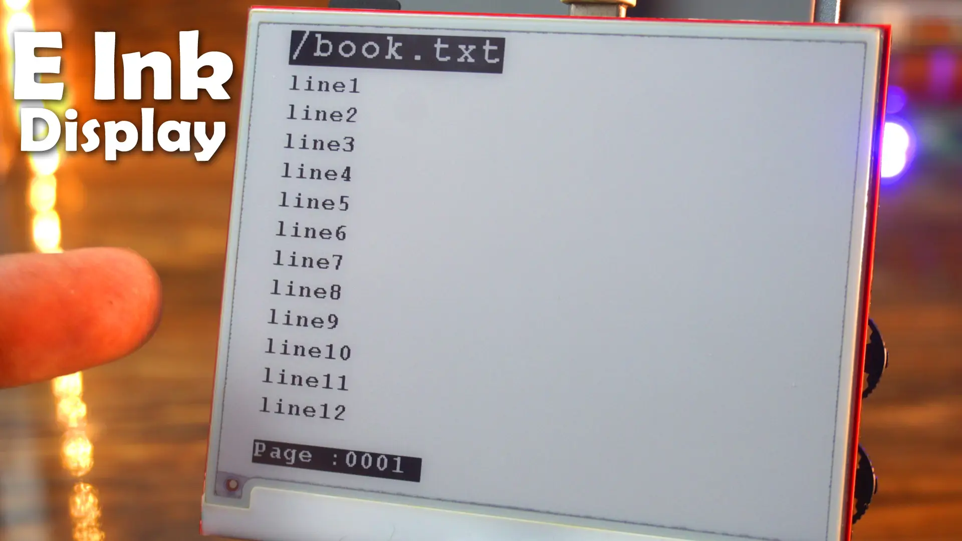
When I first saw this output, I honestly felt like I was flipping through a notebook.
The text sits there naturally, with no flicker and no light shining at me.
Unlike an LCD or OLED, this display doesn’t fight with your eyes; it just feels calm, like reading from a sheet of paper.
That’s the real beauty of E-Ink. And when I press the button on the right side, it scrolls through pages seamlessly, with the current page number.
I wanted to see if it truly behaves like paper in every way.
So, I switched off the room light… and I was completely shocked, both the real paper and the E-Ink display completely disappeared into the darkness; nothing visible at all.
Then, the moment I turned the light back on; Both came back to life. Honestly, it felt like I was looking at two sheets of paper, one digital and one real. That’s how close this display is to real paper.
Now, let’s go ahead and quickly test the remaining three examples.
fw_test Example:
This example uses some other files too, so I can’t share all those file over here. But I can show you the output.

pic_display Example:
This example displays a QR code on the display. I have already saved the QR code image onto the SD card.
|
1 2 3 4 5 6 7 8 9 10 11 12 13 14 15 16 17 18 19 20 21 22 23 24 25 26 27 28 29 30 31 32 33 34 35 36 37 38 39 40 41 42 43 44 45 46 47 48 49 50 51 52 53 54 55 56 57 58 59 60 61 62 63 64 65 66 67 68 69 70 71 72 73 74 75 76 77 78 79 80 81 82 83 84 85 86 87 88 89 90 91 92 93 94 95 96 97 98 99 100 101 102 103 104 105 106 107 108 109 110 111 112 113 114 115 116 117 118 119 120 121 122 123 124 125 126 127 128 129 130 131 132 133 134 135 136 137 138 139 140 141 142 143 144 145 146 147 148 149 150 151 152 153 154 155 156 157 |
#include "DEV_Config.h" #include "EPD.h" #include "GUI_Paint.h" #include <stdlib.h> #include "FS.h" #include "SD_MMC.h" #define SCREEN_W 400 #define SCREEN_H 300 #define BUTTON_PIN 12 #define PIN_SD_CMD 2 #define PIN_SD_CLK 42 #define PIN_SD_D0 41 #define FILE_NAME "/qr400300.bmp" UBYTE *BlackImage, *RYImage; // Red or Yellow File file; void setup() { USBSerial.begin(115200); USBSerial.println("EPD_4IN2B_V2_test Demo\r\n"); DEV_Module_Init(); pinMode(BUTTON_PIN, INPUT); SD_MMC.setPins(PIN_SD_CLK, PIN_SD_CMD, PIN_SD_D0); if (!SD_MMC.begin("/sdcard", true, true)) { USBSerial.println("Card Mount Failed"); while (1) delay(100); } USBSerial.println("e-Paper Init and Clear...\r\n"); EPD_4IN2B_V2_Init(); EPD_4IN2B_V2_Clear(); DEV_Delay_ms(500); // Create a new image cache named IMAGE_BW and fill it with white long Imagesize = SCREEN_W * SCREEN_H / 8; // long Imagesize = ((EPD_4IN2B_V2_WIDTH % 8 == 0) ? (EPD_4IN2B_V2_WIDTH / 8) : (EPD_4IN2B_V2_WIDTH / 8 + 1)) * EPD_4IN2B_V2_HEIGHT; if ((BlackImage = (UBYTE *)malloc(Imagesize)) == NULL) { USBSerial.println("Failed to apply for black memory...\r\n"); while (1) ; } if ((RYImage = (UBYTE *)malloc(Imagesize)) == NULL) { USBSerial.println("Failed to apply for red memory...\r\n"); while (1) ; } char temp[20]; sprintf(temp, "image size = %ld", Imagesize); USBSerial.println(temp); USBSerial.println("NewImage:BlackImage and RYImage\r\n"); Paint_NewImage(BlackImage, SCREEN_W, SCREEN_H, 0, WHITE); Paint_NewImage(RYImage, SCREEN_W, SCREEN_H, 0, WHITE); // Select Image Paint_SelectImage(BlackImage); Paint_Clear(WHITE); Paint_SelectImage(RYImage); Paint_Clear(WHITE); print_img(SD_MMC, FILE_NAME, SCREEN_W, SCREEN_H); EPD_4IN2B_V2_Display(BlackImage, RYImage); while (1) { if (digitalRead(BUTTON_PIN) == 0) { delay(100); if (digitalRead(BUTTON_PIN) == 0) { break; } } } USBSerial.println("Clear...\r\n"); EPD_4IN2B_V2_Clear(); USBSerial.println("Goto Sleep...\r\n"); EPD_4IN2B_V2_Sleep(); free(BlackImage); free(RYImage); BlackImage = NULL; RYImage = NULL; } void loop() { } // Display image from file void print_img(fs::FS &fs, String filename, int x, int y) { File f = fs.open(filename, "r"); if (!f) { Serial.println("Failed to open file for reading"); f.close(); return; } f.seek(54); int X = x; int Y = y; uint8_t RGB[3 * X]; for (int row = 0; row < Y; row++) // for (int row = 0; row < Y; row++) { f.seek(54 + 3 * X * row); f.read(RGB, 3 * X); uint8_t temp = 0; char index = 0; for (int colum = 0; colum < 400; colum++) { if (RGB[colum * 3] > 127) { temp = temp * 2 + 1; } else { temp = temp * 2 + 0; } // temp = 0xf0; 1111 1111 index++; if (index > 7) { BlackImage[(X * row + colum) / 8] = temp; USBSerial.println(temp); temp = 0; index = 0; } } } f.close(); } |

This looks amazing; I scanned it and it opened the Makerfabs website link.
pic_display_web Example:
Now, let’s test the 4th example, this example also displays images on the E-INK display.
|
1 2 3 4 5 6 7 8 9 10 11 12 13 14 15 16 17 18 19 20 21 22 23 24 25 26 27 28 29 30 31 32 33 34 35 36 37 38 39 40 41 42 43 44 45 46 47 48 49 50 51 52 53 54 55 56 57 58 59 60 61 62 63 64 65 66 67 68 69 70 71 72 73 74 75 76 77 78 79 80 81 82 83 84 85 86 87 88 89 90 91 92 93 94 95 96 97 98 99 100 101 102 103 104 105 106 107 108 109 110 111 112 113 114 115 116 117 118 119 120 121 122 123 124 125 126 127 128 129 130 131 132 133 134 135 136 137 138 139 140 141 142 143 144 145 146 147 148 149 150 151 152 153 154 155 156 157 158 159 160 161 162 163 164 165 166 167 168 169 170 171 172 173 174 175 176 177 178 179 180 181 182 183 184 185 186 187 188 189 190 191 192 193 194 195 196 197 198 199 200 201 202 203 204 205 206 207 208 209 210 211 212 213 214 215 216 217 218 219 220 221 222 223 224 225 226 227 228 229 230 231 232 233 234 235 236 237 238 239 240 241 242 243 244 245 246 247 248 249 250 251 252 253 254 255 256 257 258 259 260 261 262 263 264 265 266 267 268 269 270 271 272 273 274 275 276 277 278 279 280 281 282 283 284 285 286 287 288 289 290 291 292 293 294 295 296 297 298 299 300 301 302 303 304 305 306 307 308 309 310 311 312 313 314 315 316 317 318 319 320 321 322 323 324 325 326 327 328 329 330 331 332 333 334 335 336 337 338 339 340 341 342 |
#include "DEV_Config.h" #include "EPD.h" #include "GUI_Paint.h" #include <stdlib.h> #include "FS.h" #include "SD_MMC.h" #include <WiFi.h> #include <WiFiClient.h> #include <WiFiAP.h> #define SCREEN_W 400 #define SCREEN_H 300 #define SWITCH_PIN_0 12 #define SWITCH_PIN_1 5 #define SWITCH_PIN_2 17 #define SWITCH_PIN_3 47 #define SWITCH_PIN_4 48 #define SWITCH_PIN_5 18 #define PIN_SD_CMD 2 #define PIN_SD_CLK 42 #define PIN_SD_D0 41 UBYTE *BlackImage, *RYImage; // Red or Yellow File file; #define FILE_COUNT 3 int file_count = 0; String file_list[FILE_COUNT] = {"/1.bmp", "/2.bmp", "/3.bmp"}; int switch_list[6] = {SWITCH_PIN_0, SWITCH_PIN_1, SWITCH_PIN_2, SWITCH_PIN_3, SWITCH_PIN_4, SWITCH_PIN_5}; WiFiServer server(80); void setup() { hardware_init(); WiFi.mode(WIFI_AP); WiFi.softAP("Makefabs_Eink"); IPAddress myIP = WiFi.softAPIP(); USBSerial.print("AP IP address: "); USBSerial.println(myIP); server.begin(); eink_init(); img_task(); } void loop() { WiFiClient client = server.available(); // listen for incoming clients int fresh_flag = 0; if (client) { // if you get a client, USBSerial.println("New Client."); // print a message out the serial port String currentLine = ""; // make a String to hold incoming data from the client while (client.connected()) { // loop while the client's connected if (client.available()) { // if there's bytes to read from the client, char c = client.read(); // read a byte, then USBSerial.write(c); // print it out the serial monitor if (c == '\n') { // if the byte is a newline character // if the current line is blank, you got two newline characters in a row. // that's the end of the client HTTP request, so send a response: if (currentLine.length() == 0) { // HTTP headers always start with a response code (e.g. HTTP/1.1 200 OK) // and a content-type so the client knows what's coming, then a blank line: client.println("HTTP/1.1 200 OK"); client.println("Content-type:text/html"); client.println(); // the content of the HTTP response follows the header: client.print("Click <a href=\"/H\">here</a> to Change Picture.<br>"); // The HTTP response ends with another blank line: client.println(); // break out of the while loop: break; } else { // if you got a newline, then clear currentLine: currentLine = ""; } } else if (c != '\r') { // if you got anything else but a carriage return character, currentLine += c; // add it to the end of the currentLine } // Check to see if the client request was "GET /H" or "GET /L": if (currentLine.endsWith("GET /H")) { file_count++; if (file_count > 2) file_count = 0; fresh_flag = 1; client.println("HTTP/1.1 200 OK"); client.println("Content-type:text/html"); client.println(); client.print("Begin to fresh.<br>"); client.println(); } } } // close the connection: client.stop(); USBSerial.println("Client Disconnected."); } if (fresh_flag == 1) img_task(); if (switch_detect() != -1) { USBSerial.println("Clear...\r\n"); EPD_4IN2B_V2_Clear(); USBSerial.println("Goto Sleep...\r\n"); EPD_4IN2B_V2_Sleep(); free(BlackImage); free(RYImage); BlackImage = NULL; RYImage = NULL; } } void hardware_init() { pinMode(SWITCH_PIN_0, INPUT); pinMode(SWITCH_PIN_1, INPUT); pinMode(SWITCH_PIN_2, INPUT); pinMode(SWITCH_PIN_3, INPUT); pinMode(SWITCH_PIN_4, INPUT); pinMode(SWITCH_PIN_5, INPUT); USBSerial.begin(115200); USBSerial.println("EPD_4IN2B_V2_test Demo\r\n"); SD_MMC.setPins(PIN_SD_CLK, PIN_SD_CMD, PIN_SD_D0); if (!SD_MMC.begin("/sdcard", true, true)) { USBSerial.println("Card Mount Failed"); while (1) delay(100); } } void eink_init() { USBSerial.println("e-Paper Init and Clear...\r\n"); DEV_Module_Init(); EPD_4IN2B_V2_Init(); EPD_4IN2B_V2_Clear(); DEV_Delay_ms(500); // Create a new image cache named IMAGE_BW and fill it with white long Imagesize = SCREEN_W * SCREEN_H / 8; if ((BlackImage = (UBYTE *)malloc(Imagesize)) == NULL) { USBSerial.println("Failed to apply for black memory...\r\n"); while (1) ; } if ((RYImage = (UBYTE *)malloc(Imagesize)) == NULL) { USBSerial.println("Failed to apply for red memory...\r\n"); while (1) ; } } void img_task() { USBSerial.println("NewImage:BlackImage and RYImage\r\n"); Paint_NewImage(BlackImage, SCREEN_W, SCREEN_H, 0, WHITE); Paint_NewImage(RYImage, SCREEN_W, SCREEN_H, 0, WHITE); // Select Image Paint_SelectImage(BlackImage); Paint_Clear(WHITE); Paint_SelectImage(RYImage); Paint_Clear(WHITE); print_img_br(SD_MMC, file_list[file_count].c_str(), SCREEN_W, SCREEN_H); EPD_4IN2B_V2_Display(BlackImage, RYImage); } int switch_detect() { for (int i = 0; i < 6; i++) { if (digitalRead(switch_list[i]) == 0) { delay(100); if (digitalRead(switch_list[i]) == 0) { USBSerial.print("Switch Num:"); USBSerial.println(i); return i; } } } return -1; } // Display image from file void print_img(fs::FS &fs, String filename, int x, int y) { File f = fs.open(filename, "r"); if (!f) { USBSerial.println("Failed to open file for reading"); f.close(); return; } f.seek(54); int X = x; int Y = y; uint8_t RGB[3 * X]; for (int row = 0; row < Y; row++) // for (int row = 0; row < Y; row++) { f.seek(54 + 3 * X * row); f.read(RGB, 3 * X); uint8_t temp = 0; char index = 0; for (int colum = 0; colum < 400; colum++) { // 判断是否为白色 if (RGB[colum * 3] > 127) { // 白色为1 temp = temp * 2 + 1; } else { // 黑色为0 temp = temp * 2 + 0; } // temp = 0xf0; 1111 1111 index++; if (index > 7) { // BlackImage[(X * row + colum) / 8] = temp; BlackImage[(X * (299 - row) + colum) / 8] = temp; // USBSerial.println(temp); temp = 0; index = 0; } } } f.close(); } // Display image from file void print_img_br(fs::FS &fs, String filename, int x, int y) { File f = fs.open(filename, "r"); if (!f) { USBSerial.println("Failed to open file for reading"); f.close(); return; } f.seek(54); int X = x; int Y = y; uint8_t RGB[3 * X]; for (int row = 0; row < Y; row++) // for (int row = 0; row < Y; row++) { f.seek(54 + 3 * X * row); f.read(RGB, 3 * X); uint8_t temp_black = 0; uint8_t temp_red = 0; char index = 0; for (int colum = 0; colum < 400; colum++) { // 判断是否为白色 r>200 g>200 if (RGB[colum * 3] > 150 && RGB[colum * 3 + 2] > 150) { // 白色为1 temp_black = temp_black * 2 + 1; temp_red = temp_red * 2 + 1; } // 判断是否为红色 r>200 g<200 else if (RGB[colum * 3] < 150 && RGB[colum * 3 + 2] > 150) { temp_black = temp_black * 2 + 1; temp_red = temp_red * 2 + 0; } else { // 黑色为0 temp_black = temp_black * 2 + 0; temp_red = temp_red * 2 + 1; } index++; if (index > 7) { BlackImage[(X * (299 - row) + colum) / 8] = temp_black; RYImage[(X * (299 - row) + colum) / 8] = temp_red; // USBSerial.println(temp); temp_black = 0; temp_red = 0; index = 0; } } } f.close(); } |
I have already uploaded this program so let’s watch this in action.

Final Example:
This example is actually my modified version of the 4th example.
|
1 2 3 4 5 6 7 8 9 10 11 12 13 14 15 16 17 18 19 20 21 22 23 24 25 26 27 28 29 30 31 32 33 34 35 36 37 38 39 40 41 42 43 44 45 46 47 48 49 50 51 52 53 54 55 56 57 58 59 60 61 62 63 64 65 66 67 68 69 70 71 72 73 74 75 76 77 78 79 80 81 82 83 84 85 86 87 88 89 90 91 92 93 94 95 96 97 98 99 100 101 102 103 104 105 106 107 108 109 110 111 112 113 114 115 116 117 118 119 120 121 122 123 124 125 126 127 128 129 130 131 132 133 134 135 136 137 138 139 140 141 142 143 144 145 146 147 148 149 150 151 152 153 154 155 156 157 158 159 160 161 162 163 164 165 166 167 168 169 170 171 172 173 174 175 176 177 178 179 180 181 182 183 184 185 186 187 188 189 190 191 |
#include "DEV_Config.h" #include "EPD.h" #include "GUI_Paint.h" #include <stdlib.h> #include "FS.h" #include "SD_MMC.h" #define SCREEN_W 400 #define SCREEN_H 300 #define SWITCH_PIN_0 12 #define SWITCH_PIN_1 5 #define SWITCH_PIN_2 17 #define SWITCH_PIN_3 47 #define SWITCH_PIN_4 48 #define SWITCH_PIN_5 18 #define PIN_SD_CMD 2 #define PIN_SD_CLK 42 #define PIN_SD_D0 41 UBYTE *BlackImage, *RYImage; // Red or Yellow File file; #define FILE_COUNT 3 int file_count = 0; String file_list[FILE_COUNT] = {"/1.bmp", "/2.bmp", "/3.bmp"}; int switch_list[6] = {SWITCH_PIN_0, SWITCH_PIN_1, SWITCH_PIN_2, SWITCH_PIN_3, SWITCH_PIN_4, SWITCH_PIN_5}; void setup() { hardware_init(); eink_init(); img_task(); } void loop() { if (switch_detect() != -1) { USBSerial.println("Clear...\r\n"); EPD_4IN2B_V2_Clear(); USBSerial.println("Goto Sleep...\r\n"); EPD_4IN2B_V2_Sleep(); free(BlackImage); free(RYImage); BlackImage = NULL; RYImage = NULL; } } void hardware_init() { for (int i = 0; i < 6; i++) pinMode(switch_list[i], INPUT); USBSerial.begin(115200); USBSerial.println("EPD_4IN2B_V2_test Demo\r\n"); SD_MMC.setPins(PIN_SD_CLK, PIN_SD_CMD, PIN_SD_D0); if (!SD_MMC.begin("/sdcard", true, true)) { USBSerial.println("Card Mount Failed"); while (1) delay(100); } } void eink_init() { USBSerial.println("e-Paper Init and Clear...\r\n"); DEV_Module_Init(); EPD_4IN2B_V2_Init(); EPD_4IN2B_V2_Clear(); DEV_Delay_ms(500); long Imagesize = SCREEN_W * SCREEN_H / 8; if ((BlackImage = (UBYTE *)malloc(Imagesize)) == NULL) { USBSerial.println("Failed to apply for black memory...\r\n"); while (1); } if ((RYImage = (UBYTE *)malloc(Imagesize)) == NULL) { USBSerial.println("Failed to apply for red memory...\r\n"); while (1); } } void img_task() { USBSerial.println("NewImage:BlackImage and RYImage\r\n"); Paint_NewImage(BlackImage, SCREEN_W, SCREEN_H, 0, WHITE); Paint_NewImage(RYImage, SCREEN_W, SCREEN_H, 0, WHITE); // clear both buffers Paint_SelectImage(BlackImage); Paint_Clear(WHITE); Paint_SelectImage(RYImage); Paint_Clear(WHITE); // draw bitmap from SD card print_img_br(SD_MMC, file_list[file_count].c_str(), SCREEN_W, SCREEN_H); // overlay number in black Paint_SelectImage(BlackImage); Paint_DrawNum(30, 200, 12, &Font20, BLACK, WHITE); // finally refresh e-ink display EPD_4IN2B_V2_Display(BlackImage, RYImage); } int switch_detect() { for (int i = 0; i < 6; i++) { if (digitalRead(switch_list[i]) == 0) { delay(100); if (digitalRead(switch_list[i]) == 0) { USBSerial.print("Switch Num:"); USBSerial.println(i); return i; } } } return -1; } // Display image from file void print_img_br(fs::FS &fs, String filename, int x, int y) { File f = fs.open(filename, "r"); if (!f) { USBSerial.println("Failed to open file for reading"); f.close(); return; } f.seek(54); int X = x; int Y = y; uint8_t RGB[3 * X]; for (int row = 0; row < Y; row++) { f.seek(54 + 3 * X * row); f.read(RGB, 3 * X); uint8_t temp_black = 0; uint8_t temp_red = 0; char index = 0; for (int colum = 0; colum < 400; colum++) { // 判断是否为白色 r>200 g>200 if (RGB[colum * 3] > 150 && RGB[colum * 3 + 2] > 150) { temp_black = temp_black * 2 + 1; temp_red = temp_red * 2 + 1; } // 判断是否为红色 r>200 g<200 else if (RGB[colum * 3] < 150 && RGB[colum * 3 + 2] > 150) { temp_black = temp_black * 2 + 1; temp_red = temp_red * 2 + 0; } else { temp_black = temp_black * 2 + 0; temp_red = temp_red * 2 + 1; } index++; if (index > 7) { BlackImage[(X * (299 - row) + colum) / 8] = temp_black; RYImage[(X * (299 - row) + colum) / 8] = temp_red; temp_black = 0; temp_red = 0; index = 0; } } } f.close(); } |
I created a custom image for it in Photoshop. Make sure to stick to black, white, and red colors.

The white area is where we will display the numbers. Later, you can modify the code to show actual sensor values here.
Once your design is ready, save it as a .bmp file. I have already saved it to the SD card.

So, that’s all for now.
Want the complete code, project files, and resources? Download them anytime from my Patreon page.
And don’t miss the full step-by-step video on my YouTube channel; it’s all there to help you build this project yourself!
Frequently Asked Questions (FAQ)
1. What is E-Ink technology and how does it work?
E-Ink, or Electronic Paper, is a display technology that mimics the appearance of printed paper. It works by using millions of tiny microcapsules containing charged particles (e.g., black, white, and red). An electric field is applied to move these particles to the surface, forming text and images. Unlike LCDs, it doesn’t use a backlight; instead, it reflects ambient light, making it comfortable to read.
2. Why is an E-Ink display so energy efficient?
E-Ink displays are extremely low-power because they only consume energy when the content on the screen is changing. Once an image or text is displayed, it requires almost zero power to hold it there. As demonstrated in the article, the image remains visible even after the power is disconnected.
3. What specific board is used in this tutorial?
This tutorial features the MaTouch ESP32-S3 board from Makerfabs. It comes integrated with a 4.2-inch triple-color (black, white, and red) E-Ink display, an ESP32-S3 microcontroller, Wi-Fi, Bluetooth, an SD card slot, and multiple interfaces for projects.
4. How do you program this E-Ink display with Arduino?
To program the display, you need to use the Arduino IDE. The essential steps are:
- Set up the Arduino IDE with the correct ESP32 board package (version 2.0.11 is recommended).
- Download the project files from the Makerfabs GitHub repository.
- Manually install the required ESP32-waveshare-epd library by adding it as a .ZIP library in the Arduino IDE.
- Configure the board settings in the Tools menu (Board: ESP32S3 Dev Module, Flash Size: 16MB, PSRAM: OPI PSRAM).
5. Can I display my own custom images or text on this screen?
Yes. The article shows two methods:
- For Images: You can create your own graphics in an editor like Photoshop using only black, white, and red. Save the file as a .bmp and copy it to the SD card.
- For Text: For the “Ebook” example, you can simply edit a .txt file with your desired content and save it to the SD card. The code will then read and display it.
Watch Video Tutorial:

Discover more from Electronic Clinic
Subscribe to get the latest posts sent to your email.


