ESP32 Timer Switch Relay with Touch Display & Encoder | MaTouch 1.28 Review
Last Updated on September 26, 2025 by Engr. Shahzada Fahad
Table of Contents
Description:
Build a powerful ESP32 Timer Switch Relay using the MaTouch 1.28 board. This tutorial shows you how to control 8 channels with a touch display and rotary encoder. Learn to create a custom UI with SquareLine Studio and LVGL for your next home automation project.
With this development board, you can manage everything just through the display. Using the encoder, you can easily select any load you want… and with a single switch, turn it ON or OFF.

But that’s not all. If you want any load to turn ON or OFF at a specific time, you can do that too.
The addition of the encoder is simply brilliant. With it, you can not only select loads, but also adjust values, scroll through menu items, and much more. There are endless possibilities with this setup.
Introduction:
Another great product from Makerfabs; the MaTouch 1.28” Toolset Timer Switch Relay.

The moment I saw this board, I was really impressed, and instantly a lot of project ideas started popping into my head.
You have probably already noticed; it’s made up of two parts. The top part is completely detachable, and that’s exactly what makes this board special.
All the essential components are already on this board, which means I can easily use it in other projects too; like for sensor monitoring, or even as a remote controller. In fact, I can use it in any project where I’d normally use an ESP32.
I have got some really fun projects planned with this board, so make sure to subscribe if you don’t want to miss this amazing series of videos and articles!
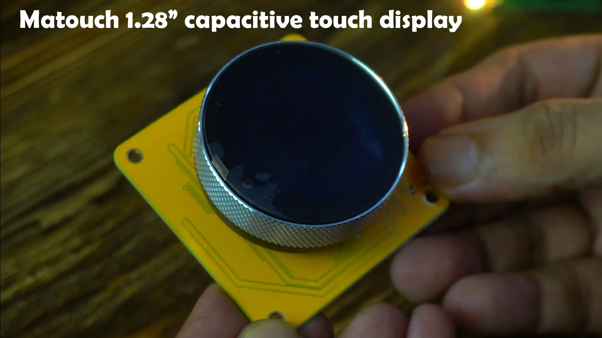
This is the Matouch 1.28” capacitive touch display with a built-in encoder and pushbutton.
Normally, you can control everything through the on-screen switches in the UI. But let’s say you are using it on a bike, or in any situation where you are wearing gloves. In that case, turning a switch ON/OFF through touch becomes difficult. That’s where the physical button feature really shines.
The same goes for the encoder.
With gloves on, controlling sliders or adjusting values on a touchscreen isn’t practical. But with the encoder, you can easily scroll through options or fine-tune values, no matter the situation.
I have prepared some simple examples for you, so you will get a clear idea of how to design the UI for this display, and how to integrate both the encoder and button in your projects. Trust me, once you see this in action, you will realize how powerful and versatile this little display really is.

On the bottom side, you will find the most versatile part of this board; my favorite; the ESP32-S3 WiFi + Bluetooth module.
Alongside it, there’s a vibration motor, USB-C port for uploading and debugging, a battery holder for the RTC, boot and reset buttons, and plenty of headers for connecting relays, sensors, and other breakout boards.
The only thing missing here is proper pin labeling, which would have made prototyping much easier. But since this is an open-source project, you do get the schematic and PCB design files, so you can always check and confirm every connection yourself.

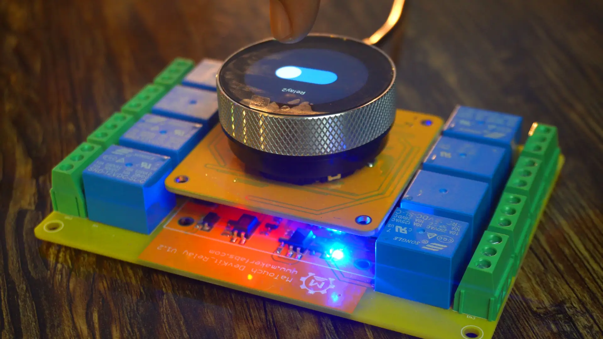
This is an 8-channel relay board with optocoupler isolation. This means safety first; your low-voltage controller is completely protected from the high-voltage side.
This board has its own regulated power supply, so with just a simple 12V DC adaptor, you can safely power both the relay board and your controller board. No messy wiring, no complicated setups; just plug it in and take control.
This Timer Switch comes preloaded with Makerfabs own firmware interface. So let’s first power it up and check out how it looks with the company firmware.

Now, don’t get confused by the interface you see here. Because in this article, I will also be sharing some basic examples that will give you a complete idea of how to design your own interface in Squareline Studio, and how to use both the encoder and the push button.
Anyway, here you can easily set the time using the encoder along with the on-screen buttons.
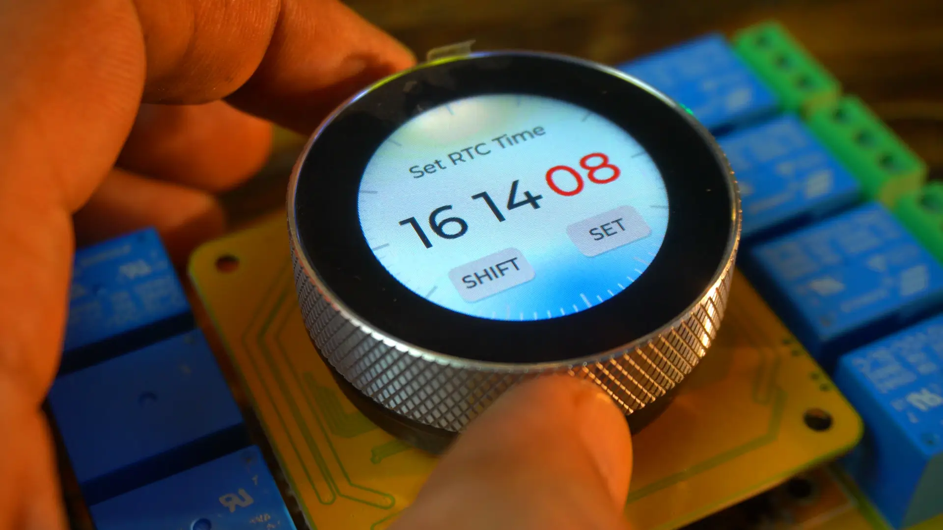
And once you have set the time, just press the Set button; boom! It takes you straight to another screen.
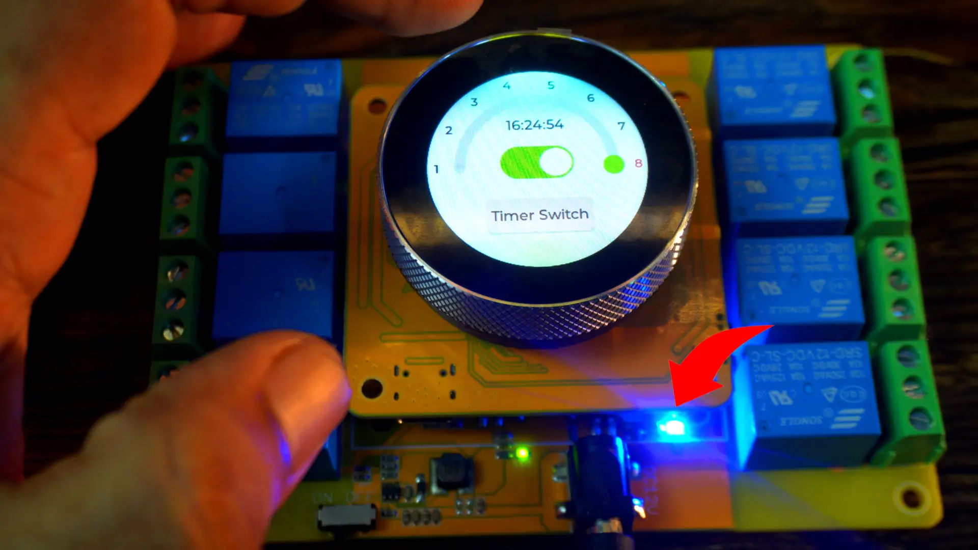
First, we used the encoder to set the time, and now we can use the same encoder to select which relay we want to control. After that, we can use this switch to turn the selected relay ON or OFF.
When we turn the relay ON or OFF, the indicator LED on the relay board also turns ON or OFF; giving us a clear visual confirmation.
So far, this was the manual way of controlling all eight relays. But if you want to automatically control all eight relays, or just specific ones, here’s how: first, select the relay you want, and then press the Timer Switch button.
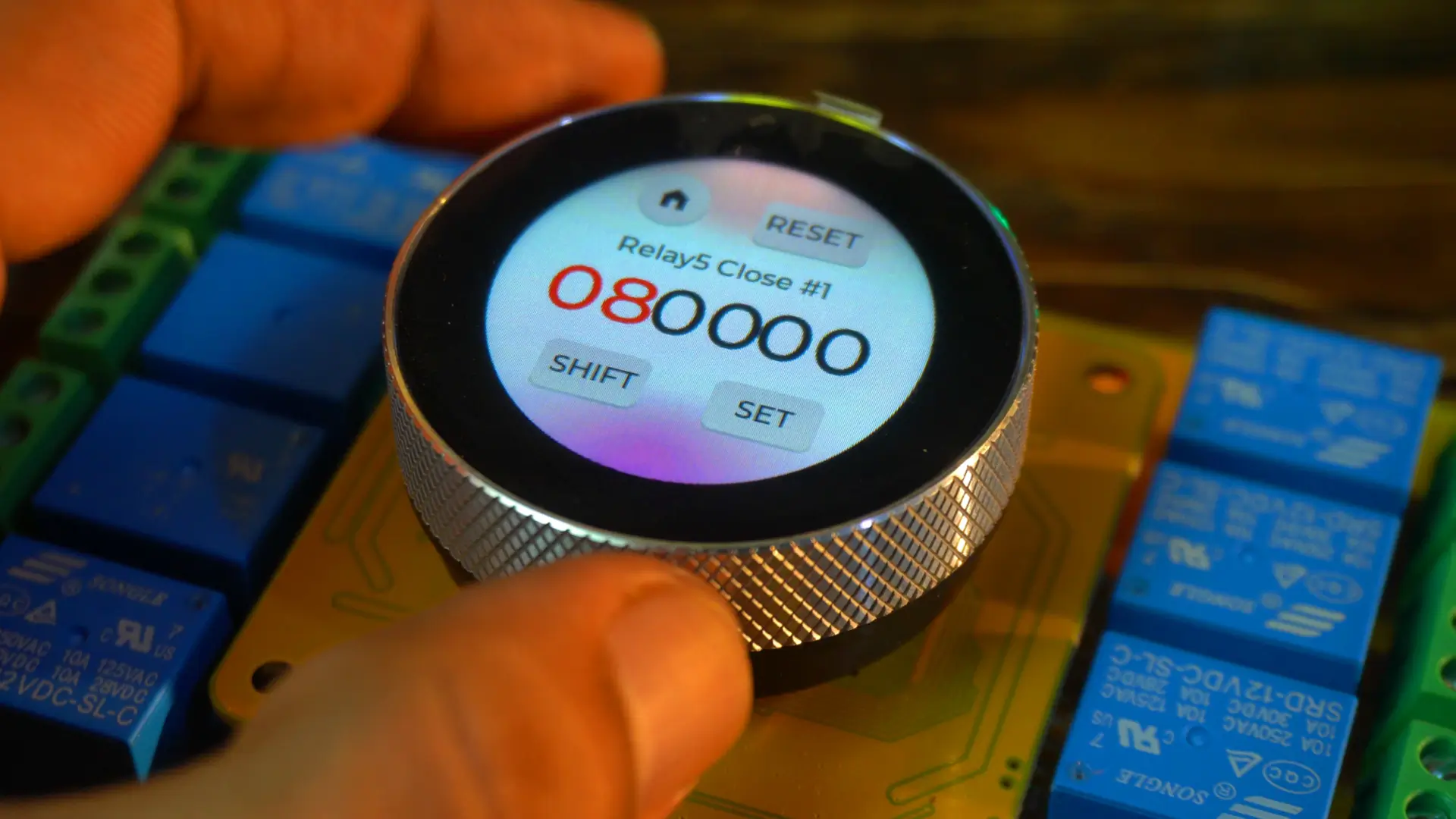
You can set the exact time for the relay to turn ON; and the exact time for it to turn OFF.
Let me quickly demonstrate this for you. I’m going to control Relay 4 automatically.
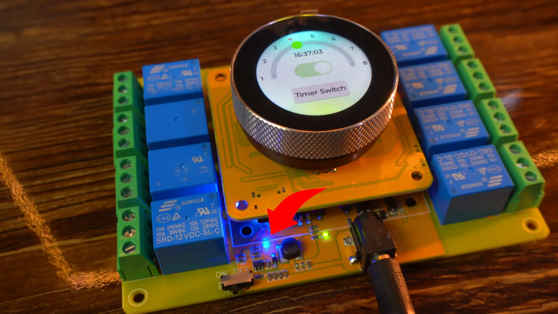
And there you go; amazing! The relay just turned ON.
Now this is the future of home automation; and the best part is, now everyone can enjoy futuristic home automation because this board is quite affordable.
And then it turned off automatically.
It supports a maximum of 5 groups of timers, which means you can set up to 5 different timings for each relay. For example, if you want to control a room heater at different times of the day, you can schedule it; let’s say from 6 AM to 8 AM, then again from 1 PM to 2 PM, and later from 5 PM to 7 PM, and so on.
This feature is really handy if you want to turn one or multiple loads on and off at different times automatically.
So, if your only goal is to control loads, then this board is ready to use straight out of the box.
But if you want to add your own custom features, redesign its UI, control it via a Bluetooth app or through the Blynk application, or even use it as a portable receiver or transmitter, then make sure you keep reading this article. Because we will be using some features right now, and some we will cover in the upcoming videos and articles.
First, you need to go to Makerfabs official GitHub repository and download the complete zip folder. Because in that folder, you will find everything related to this board.
Now, if you look at the company’s firmware code, any beginner might get scared just by seeing it. That’s why before diving into company’s firmware code, you should start with the simple examples that I have created for you.
About the Arduino IDE and ESP32:
Before we start, let me quickly share my software setup. Right now, I am using the
- Arduino IDE version 2.3.4
- ESP32 board package version 2.0.11
- LVGL version 8.3.11 and
- ESP32Time library version 2.0.6
All of my recent touch display projects have been done with the same versions, and they have worked smoothly. So, if you want to follow along without running into errors, I recommend using the same setup.
I have created a simple template folder for you. Inside this folder, you will find two more folders.
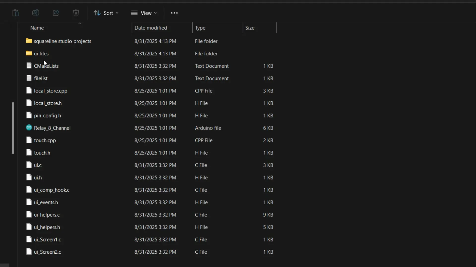
One is for saving the Squareline Studio project files, and the other; UI Files folder; is where we will store the UI files generated by Squareline Studio.
I have already explained this setup in my previous projects.
Now, let’s move on.
Importing SquareLine Studio Project:
Open Squareline Studio, click on IMPORT PROJECT, and browse to the SquareLine Studio projects folder. Select the project file, then click the Open button.
Next, go to the File menu and open Project Settings.
- Set the Shape to Circle.
- For the Project Export Root, click on Browse and select the same Squareline Studio projects folder.
- For the UI Files Export Path, choose the UI Files folder.
- For the LVGL Include Path, simply type: lvgl.h.
- Make sure to check the option Flat export (exports all files to one folder).
Finally, click the APPLY CHANGES button, and you are all set!
Everything I just explained, I have already covered all of this step by step in my SquareLine Studio–based projects. So, if you want to understand things from the very basics, you should definitely check out my “Getting Started” articles on SquareLine Studio and LVGL.
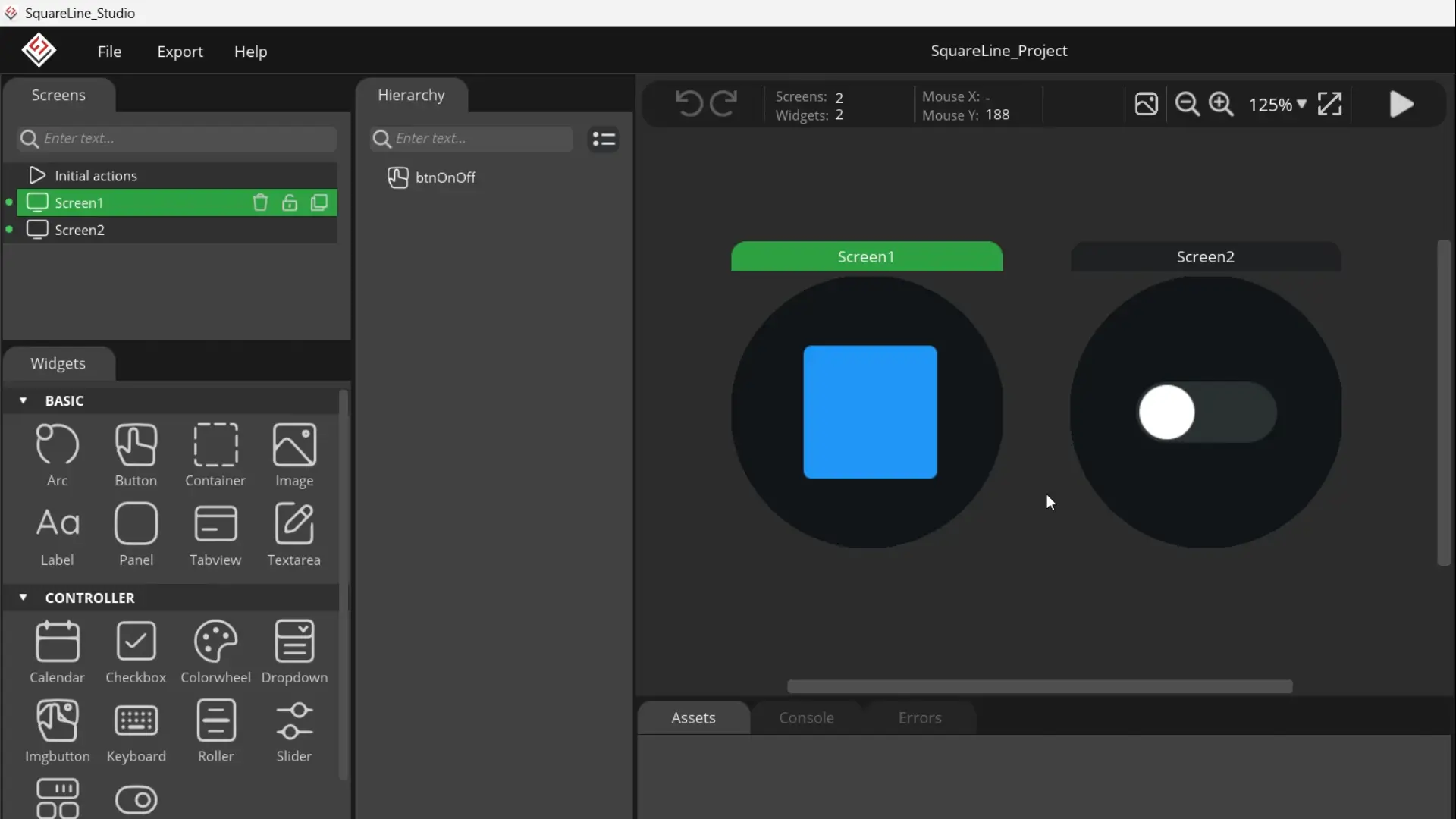
For testing, I have only added these two screens.
Before building a complicated UI, you should always start with a simple one. This makes troubleshooting much easier. Once everything is working perfectly, then you can move on to your actual design.
After creating a basic UI, the very first step is to save the project.
Next, go to the Export menu and click Export UI Files.
Now, open the UI files folder, copy all the files, and paste them into your Arduino project folder where the main .ino file is located. Finally, go ahead and open the arduino main .ino file. All the UI files will be automatically loaded. I am going to share the main code, but if you need the complete template folder; you can download it from my Patreon page. And let me tell you, I have slightly modified this code to make it easier for you.
Uploading the program into ESP32S3:
|
1 2 3 4 5 6 7 8 9 10 11 12 13 14 15 16 17 18 19 20 21 22 23 24 25 26 27 28 29 30 31 32 33 34 35 36 37 38 39 40 41 42 43 44 45 46 47 48 49 50 51 52 53 54 55 56 57 58 59 60 61 62 63 64 65 66 67 68 69 70 71 72 73 74 75 76 77 78 79 80 81 82 83 84 85 86 87 88 89 90 91 92 93 94 95 96 97 98 99 100 101 102 103 104 105 106 107 108 109 110 111 112 113 114 115 116 117 118 119 120 121 122 123 124 125 126 127 128 129 130 131 132 133 134 135 136 137 138 139 140 141 142 143 144 145 146 147 148 149 150 151 152 153 154 155 156 157 158 159 160 161 162 163 164 165 166 167 168 169 170 171 172 173 174 175 176 177 178 179 180 181 182 183 184 185 186 187 188 189 190 191 192 193 194 195 196 197 198 199 200 201 202 203 204 205 206 207 208 209 210 211 212 213 214 215 216 217 218 219 220 221 222 223 224 225 226 227 228 229 230 231 232 233 234 235 236 237 238 239 240 241 242 243 244 245 246 247 248 249 250 251 252 253 254 255 256 257 258 259 260 261 262 263 264 265 266 267 268 269 270 271 272 273 274 275 276 277 278 279 280 281 282 283 284 285 286 287 288 289 290 291 292 293 294 295 296 297 298 299 300 301 302 303 304 305 306 307 308 309 310 311 312 313 314 315 316 317 318 319 320 321 322 323 324 325 326 327 328 329 330 331 332 333 334 335 336 337 338 339 340 341 342 343 344 345 346 347 348 349 350 351 352 353 354 355 356 357 358 359 360 361 362 363 364 365 366 367 368 369 370 371 372 373 374 375 376 377 378 379 380 381 382 383 384 385 386 387 388 389 390 391 392 393 394 395 396 397 398 399 400 401 402 403 404 405 406 407 408 409 410 411 412 413 414 415 416 417 418 419 420 421 422 423 424 425 426 427 428 429 430 431 432 433 434 435 436 437 438 439 440 441 442 443 444 445 446 447 448 449 450 451 452 453 454 455 456 457 458 459 460 461 462 463 464 465 466 467 468 469 470 471 472 473 474 475 476 477 478 479 480 481 482 483 484 485 486 487 488 489 490 491 492 493 494 495 496 497 498 499 500 501 502 503 504 505 506 507 508 509 510 511 512 513 514 515 516 517 518 519 520 521 522 523 524 525 526 527 528 529 530 531 532 533 534 535 536 537 538 539 540 541 542 543 544 545 546 547 548 549 550 551 552 553 554 555 556 557 558 559 560 561 562 563 564 565 566 567 568 569 570 571 572 573 574 575 576 577 578 579 580 581 582 583 584 585 586 587 588 589 590 591 592 593 594 595 596 597 598 599 600 601 602 603 604 605 606 607 608 609 610 611 612 613 614 615 616 617 618 619 620 621 622 623 624 625 626 627 628 629 630 631 632 633 634 635 636 637 638 639 640 641 642 643 644 645 646 647 648 649 650 651 652 653 654 655 656 657 658 659 660 661 662 663 664 665 666 667 668 669 670 671 672 673 674 675 676 677 678 679 680 681 682 683 684 685 686 687 688 689 690 691 692 693 |
#include <lvgl.h> #include <Arduino_GFX_Library.h> #include "ui.h" #include <RTClib.h> #include <ESP32Time.h> #include "touch.h" #include "pin_config.h" #include "local_store.h" /*Change to your screen resolution*/ static const uint16_t screenWidth = 240; static const uint16_t screenHeight = 240; static lv_disp_draw_buf_t draw_buf; static lv_color_t buf[screenWidth * screenHeight / 10]; Arduino_ESP32SPI *bus = new Arduino_ESP32SPI(TFT_DC, TFT_CS, TFT_SCLK, TFT_MOSI, TFT_MISO, HSPI, true); // Constructor Arduino_GFX *gfx = new Arduino_GC9A01(bus, TFT_RES, 2 /* rotation */, true /* IPS */); RTC_PCF8563 rtc_pcf; ESP32Time rtc_esp; int counter = 0; int State; int old_State; int move_flag = 0; // Global int time_shift_index = 0; // hour,min,sec sequential int rtc_set_flag = 0; int page_index = 0; int alarm_set_flag = 0; int alarm_reset_flag = 0; int alarm_load_flag = 0; int alarm_store_flag = 0; int relay_flag = 0; // Switch Single Control flag int relay_state = 0; // Switching state transmit a value // Local int relay_inedx = 0; // Relay Number int relay_status[8] = {0}; // Relay status int alarm_index = 0; // Alarm Clock Number int alarm_status = 0; typedef struct My_time { int hou; int min; int sec; }; My_time t_set = {0, 0, 0}; My_time t_clock = {0, 0, 0}; My_time t_alarm = {0, 0, 0}; //8 relays, 10 sets of clocks, 6 hours, minutes, seconds + 1 end symbol '/0' char alarm_data[8][10][7]; int relay_pin[8]{ RELAY1_PIN, RELAY2_PIN, RELAY3_PIN, RELAY4_PIN, RELAY5_PIN, RELAY6_PIN, RELAY7_PIN, RELAY8_PIN}; void setup() { Serial.begin(115200); /* prepare for possible serial debug */ delay(1000); pin_init(); for (int i = 0; i < 8; i++) set_relay(i, 0); //Set the relay switches to set all 8 to 0; Wire.begin(TOUCH_SDA, TOUCH_SCL); rtc_pcf_init(); alarm_data_init(); // Alarm clock initialisation, read flash data, flash with data will be assigned value, no data will be set to ---. alarm_data_print(); gfx->begin(); delay(200); lv_init(); lv_disp_draw_buf_init(&draw_buf, buf, NULL, screenWidth * screenHeight / 10); /*Initialize the display*/ static lv_disp_drv_t disp_drv; lv_disp_drv_init(&disp_drv); /*Change the following line to your display resolution*/ disp_drv.hor_res = screenWidth; disp_drv.ver_res = screenHeight; disp_drv.flush_cb = my_disp_flush; disp_drv.draw_buf = &draw_buf; lv_disp_drv_register(&disp_drv); /*Initialize the (dummy) input device driver*/ static lv_indev_drv_t indev_drv; lv_indev_drv_init(&indev_drv); indev_drv.type = LV_INDEV_TYPE_POINTER; indev_drv.read_cb = my_touchpad_read; lv_indev_drv_register(&indev_drv); ui_init(); Serial.println("Setup done"); xTaskCreatePinnedToCore(Task_TFT, "Task_TFT", 10240, NULL, 2, NULL, 0); xTaskCreatePinnedToCore(Task_main, "Task_main", 4096, NULL, 1, NULL, 1); xTaskCreatePinnedToCore(Task_time, "Task_time", 4096, NULL, 3, NULL, 1); } long runtime = 0; void loop() { lv_timer_handler(); /* let the GUI do its work */ delay(5); } void Task_TFT(void *pvParameters) // screen refresh { while (1) { lv_timer_handler(); vTaskDelay(50); } } void Task_main(void *pvParameters) // Relay and alarm settings { while (1) { // screen 1 Sets the time of the RTC. if (rtc_set_flag == 1) { rtc_reset(); rtc_set_flag = 0; time_shift_index = 0; } relay_event(); // Relay control alarm_event(); // Alarm reset, load, save // Encoder function encoder_func(); // UI State Refresh obj_update(); vTaskDelay(100); } } // Determine whether the alarm clock and the current time match, match the corresponding switch relays void Task_time(void *pvParameters) { while (1) { DateTime now = rtc_pcf.now(); // Update real time t_clock.hou = now.hour(); t_clock.min = now.minute(); t_clock.sec = now.second(); char now_time[7]; sprintf(now_time, "%02d%02d%02d", t_clock.hou, t_clock.min, t_clock.sec); for (int i = 0; i < 8; i++) { for (int j = 0; j < 10; j++) { if (alarm_check(i, j, now_time)) //Determine whether the alarm clock and the current time match { Serial.println("Alarm detect"); if (j % 2 == 0) set_relay(i, 1); else set_relay(i, 0); } } } vTaskDelay(500); } } void relay_event() { if (relay_flag == 1) { set_relay(relay_inedx, relay_state); relay_flag = 0; } } void alarm_event() { if (alarm_reset_flag == 1) { alarm_data_reset(relay_inedx); alarm_index = 0; alarm_load_flag = 1; alarm_reset_flag = 0; } if (alarm_load_flag == 1) { if (alarm_data[relay_inedx][alarm_index][0] == '-') { alarm_status = 0; t_alarm.hou = 0; t_alarm.min = 0; t_alarm.sec = 0; } else { alarm_status = 1; char *temp = alarm_data[relay_inedx][alarm_index]; t_alarm.hou = (temp[0] - '0') * 10 + (temp[1] - '0'); t_alarm.min = (temp[2] - '0') * 10 + (temp[3] - '0'); t_alarm.sec = (temp[4] - '0') * 10 + (temp[5] - '0'); } alarm_load_flag = 0; } if (alarm_set_flag == 1) { if (alarm_status == 1) { char temp[7]; sprintf(temp, "%02d%02d%02d", t_alarm.hou, t_alarm.min, t_alarm.sec); alarm_data_update(relay_inedx, alarm_index, temp); } alarm_index++; if (alarm_index > 9) alarm_index = 0; alarm_load_flag = 1; time_shift_index = 0; alarm_set_flag = 0; } if (alarm_store_flag == 1) { alarm_data_print(); alarm_data_restore(relay_inedx); alarm_index = 0; alarm_store_flag = 0; } } //--------------------------------------------- void pin_init() { pinMode(TFT_BLK, OUTPUT); digitalWrite(TFT_BLK, HIGH); pinMode(BUTTON_PIN, INPUT_PULLUP); pinMode(ENCODER_CLK, INPUT_PULLUP); pinMode(ENCODER_DT, INPUT_PULLUP); old_State = digitalRead(ENCODER_CLK); attachInterrupt(ENCODER_CLK, encoder_irq, CHANGE); for (int i = 0; i < 8; i++) { pinMode(relay_pin[i], OUTPUT); digitalWrite(relay_pin[i], 0); } } void encoder_irq() { State = digitalRead(ENCODER_CLK); if (State != old_State) { if (digitalRead(ENCODER_DT) == State) { counter++; } else { counter--; } } old_State = State; // the first position was changed } /* Display flushing */ void my_disp_flush(lv_disp_drv_t *disp, const lv_area_t *area, lv_color_t *color_p) { uint32_t w = (area->x2 - area->x1 + 1); uint32_t h = (area->y2 - area->y1 + 1); #if (LV_COLOR_16_SWAP != 0) gfx->draw16bitBeRGBBitmap(area->x1, area->y1, (uint16_t *)&color_p->full, w, h); #else gfx->draw16bitRGBBitmap(area->x1, area->y1, (uint16_t *)&color_p->full, w, h); #endif lv_disp_flush_ready(disp); } /*Read the touchpad*/ void my_touchpad_read(lv_indev_drv_t *indev_driver, lv_indev_data_t *data) { int touchX = 0, touchY = 0; if (read_touch(&touchX, &touchY) == 1) { data->state = LV_INDEV_STATE_PR; data->point.x = (uint16_t)(240 - touchX); data->point.y = (uint16_t)(240 - touchY); } else { data->state = LV_INDEV_STATE_REL; } } // UI void obj_update() { char temp[40]; if (page_index == 0) { sprintf(temp, "%02d", t_set.hou); lv_label_set_text(ui_Label1, temp); sprintf(temp, "%02d", t_set.min); lv_label_set_text(ui_Label2, temp); sprintf(temp, "%02d", t_set.sec); lv_label_set_text(ui_Label3, temp); if (time_shift_index == 0) lv_obj_set_style_text_color(ui_Label1, TXT_RED, LV_PART_MAIN | LV_STATE_DEFAULT); else lv_obj_set_style_text_color(ui_Label1, TXT_BLACK, LV_PART_MAIN | LV_STATE_DEFAULT); if (time_shift_index == 1) lv_obj_set_style_text_color(ui_Label2, TXT_RED, LV_PART_MAIN | LV_STATE_DEFAULT); else lv_obj_set_style_text_color(ui_Label2, TXT_BLACK, LV_PART_MAIN | LV_STATE_DEFAULT); if (time_shift_index == 2) lv_obj_set_style_text_color(ui_Label3, TXT_RED, LV_PART_MAIN | LV_STATE_DEFAULT); else lv_obj_set_style_text_color(ui_Label3, TXT_BLACK, LV_PART_MAIN | LV_STATE_DEFAULT); } else if (page_index == 1) { sprintf(temp, "%02d:%02d:%02d", t_clock.hou, t_clock.min, t_clock.sec); lv_label_set_text(ui_Label25, temp); if (relay_status[relay_inedx] == 0) lv_obj_clear_state(ui_Switch1, LV_STATE_CHECKED); else lv_obj_add_state(ui_Switch1, LV_STATE_CHECKED); if (relay_status[0] == 0) lv_obj_set_style_text_color(ui_Label7, TXT_BLACK, LV_PART_MAIN | LV_STATE_DEFAULT); else lv_obj_set_style_text_color(ui_Label7, TXT_RED, LV_PART_MAIN | LV_STATE_DEFAULT); if (relay_status[1] == 0) lv_obj_set_style_text_color(ui_Label8, TXT_BLACK, LV_PART_MAIN | LV_STATE_DEFAULT); else lv_obj_set_style_text_color(ui_Label8, TXT_RED, LV_PART_MAIN | LV_STATE_DEFAULT); if (relay_status[2] == 0) lv_obj_set_style_text_color(ui_Label9, TXT_BLACK, LV_PART_MAIN | LV_STATE_DEFAULT); else lv_obj_set_style_text_color(ui_Label9, TXT_RED, LV_PART_MAIN | LV_STATE_DEFAULT); if (relay_status[3] == 0) lv_obj_set_style_text_color(ui_Label10, TXT_BLACK, LV_PART_MAIN | LV_STATE_DEFAULT); else lv_obj_set_style_text_color(ui_Label10, TXT_RED, LV_PART_MAIN | LV_STATE_DEFAULT); if (relay_status[4] == 0) lv_obj_set_style_text_color(ui_Label11, TXT_BLACK, LV_PART_MAIN | LV_STATE_DEFAULT); else lv_obj_set_style_text_color(ui_Label11, TXT_RED, LV_PART_MAIN | LV_STATE_DEFAULT); if (relay_status[5] == 0) lv_obj_set_style_text_color(ui_Label12, TXT_BLACK, LV_PART_MAIN | LV_STATE_DEFAULT); else lv_obj_set_style_text_color(ui_Label12, TXT_RED, LV_PART_MAIN | LV_STATE_DEFAULT); if (relay_status[6] == 0) lv_obj_set_style_text_color(ui_Label13, TXT_BLACK, LV_PART_MAIN | LV_STATE_DEFAULT); else lv_obj_set_style_text_color(ui_Label13, TXT_RED, LV_PART_MAIN | LV_STATE_DEFAULT); if (relay_status[7] == 0) lv_obj_set_style_text_color(ui_Label14, TXT_BLACK, LV_PART_MAIN | LV_STATE_DEFAULT); else lv_obj_set_style_text_color(ui_Label14, TXT_RED, LV_PART_MAIN | LV_STATE_DEFAULT); } else if (page_index == 2) { if (alarm_index % 2 == 0) { sprintf(temp, "Relay%d Open #%d", relay_inedx + 1, alarm_index / 2 + 1); } else { sprintf(temp, "Relay%d Close #%d", relay_inedx + 1, alarm_index / 2 + 1); } lv_label_set_text(ui_Label22, temp); if (alarm_status == 0) { lv_label_set_text(ui_Label19, "--"); lv_label_set_text(ui_Label20, "--"); lv_label_set_text(ui_Label21, "--"); } else { sprintf(temp, "%02d", t_alarm.hou); lv_label_set_text(ui_Label19, temp); sprintf(temp, "%02d", t_alarm.min); lv_label_set_text(ui_Label20, temp); sprintf(temp, "%02d", t_alarm.sec); lv_label_set_text(ui_Label21, temp); } if (time_shift_index == 0) lv_obj_set_style_text_color(ui_Label19, TXT_RED, LV_PART_MAIN | LV_STATE_DEFAULT); else lv_obj_set_style_text_color(ui_Label19, TXT_BLACK, LV_PART_MAIN | LV_STATE_DEFAULT); if (time_shift_index == 1) lv_obj_set_style_text_color(ui_Label20, TXT_RED, LV_PART_MAIN | LV_STATE_DEFAULT); else lv_obj_set_style_text_color(ui_Label20, TXT_BLACK, LV_PART_MAIN | LV_STATE_DEFAULT); if (time_shift_index == 2) lv_obj_set_style_text_color(ui_Label21, TXT_RED, LV_PART_MAIN | LV_STATE_DEFAULT); else lv_obj_set_style_text_color(ui_Label21, TXT_BLACK, LV_PART_MAIN | LV_STATE_DEFAULT); } } void encoder_func() { if (page_index == 0) { encoder_set_time(&t_set); } else if (page_index == 1) { encoder_set_arc(ui_Arc1, &relay_inedx); } else if (page_index == 2) { if (counter != 0) alarm_status = 1; encoder_set_time(&t_alarm); } } void rtc_pcf_init() { if (!rtc_pcf.begin()) { Serial.println("Couldn't find RTC"); Serial.flush(); while (1) delay(10); } if (rtc_pcf.lostPower()) { Serial.println("PCF8563 is NOT initialized, let's set the time!"); rtc_pcf.adjust(DateTime(2024, 1, 1, 0, 0, 0)); } rtc_pcf.start(); DateTime now = rtc_pcf.now(); t_set.hou = now.hour(); t_set.min = now.minute(); t_set.sec = now.second(); char temp[40]; sprintf(temp, "PCF time %02d:%02d:%02d", t_set.hou, t_set.min, t_set.sec); Serial.println(temp); } void rtc_reset() { rtc_pcf.adjust(DateTime(2024, 1, 1, t_set.hou, t_set.min, t_set.sec)); DateTime now = rtc_pcf.now(); Serial.print(now.hour(), DEC); Serial.print(':'); Serial.print(now.minute(), DEC); Serial.print(':'); Serial.print(now.second(), DEC); Serial.println(); rtc_esp.setTime(now.second(), now.minute(), now.hour(), 1, 1, 2024); // 17th Jan 2021 1:2:3 // Serial.println(rtc_esp.getTime("%A, %B %d %Y %H:%M:%S")); Serial.println(rtc_esp.getTime()); // (String) 15:24:38 } // encouder void encoder_set_time(My_time *my_t) { if (time_shift_index == 0) //hour { my_t->hou += counter; if (my_t->hou > 23) my_t->hou = 23; if (my_t->hou < 0) my_t->hou = 0; } else if (time_shift_index == 1) //min { my_t->min += counter; if (my_t->min > 59) my_t->min = 59; if (my_t->min < 0) my_t->min = 0; } else if (time_shift_index == 2) //sec { my_t->sec += counter; if (my_t->sec > 59) my_t->sec = 59; if (my_t->sec < 0) my_t->sec = 0; } counter = 0; } void encoder_set_arc(lv_obj_t *arc, int *value) { int min = lv_arc_get_min_value(arc); int max = lv_arc_get_max_value(arc); *value += counter; counter = 0; if (*value > max) *value = max; if (*value < min) *value = min; lv_arc_set_value(arc, *value); lv_obj_invalidate(arc); } void set_relay(int num, int status) { char temp[30]; sprintf(temp, "Num %d, set status %d", num, status); Serial.println(temp); relay_status[num] = status; digitalWrite(relay_pin[num], status); } // Alarm data // char alarm_data[8][10][7]; // Alarm clock initialisation, read flash data, flash with data will be assigned value, no data will be set to ---. void alarm_data_init() { const char *init_string = "------"; for (int i = 0; i < 8; i++) //8 channels { char key_name[10]; char nvs_data[80]; sprintf(key_name, "DATA_%d", i); if (read_nvs(key_name, nvs_data) == SUCCESS) { Serial.println("Read NVS Success"); Serial.println(nvs_data); for (int j = 0; j < 10; j++) //10 alarm clocks { for (int k = 0; k < 6; k++) //6 characters (hour, minute and second data) { alarm_data[i][j][k] = nvs_data[j * 6 + k]; //Assign the read characters one by one to the alarm clock data } alarm_data[i][j][6] = '\0';//string terminator } } else { Serial.println("Read NVS ERROR"); alarm_data_reset(i);//No data read. Reset to ‘------’. alarm_data_restore(i); } } // 应该是从NVS读的 // const char *init_string = "------"; // for (int i = 0; i < 8; i++) // { // for (int j = 0; j < 10; j++) // { // strcpy(alarm_data[i][j], init_string); // } // } } void alarm_data_update(int relay_num, int index, char *time) { strcpy(alarm_data[relay_num][index], time); } void alarm_data_reset(int relay_num) { const char *init_string = "------"; for (int j = 0; j < 10; j++) { strcpy(alarm_data[relay_num][j], init_string); } } int alarm_check(int relay_num, int index, char *time) { if (alarm_data[relay_num][index][0] == '-') return 0; if (strcmp(alarm_data[relay_num][index], time) == 0) return 1; else return 0; } void alarm_data_print() { for (int i = 0; i < 8; i++) { Serial.printf("Relay %d\n", i); for (int j = 0; j < 10; j++) { Serial.printf(alarm_data[i][j]); Serial.printf(","); } Serial.println(); } } void alarm_data_restore(int relay_num) { char nvs_data[80] = ""; for (int j = 0; j < 10; j++) { // strcat(nvs_data, alarm_data[relay_num][j]); for (int k = 0; k < 6; k++) { nvs_data[j * 6 + k] = alarm_data[relay_num][j][k]; } } nvs_data[60] = '\0'; Serial.println(nvs_data); Serial.println(sizeof(nvs_data)); char key_name[10]; sprintf(key_name, "DATA_%d", relay_num); write_nvs(key_name, nvs_data); } |
Uploading the Program:
To upload the program, here is what you need to do:
First, go to the Tools menu > Board > ESP32, and select ESP32S3 Dev Module.
Go back to the Tools Menu > Port, and choose the correct communication port.
Again to the tools menu > Flash Size, and select 16MB.
Again go to the Tools menu > Partition Scheme and select 16M Flash
And one last time, go to Tools Menu > PSRAM, and select OPI PSRAM.
Once these settings are done, you can simply click the Upload button.
These same settings will be required for all the example programs we will test.
Practical Demonstration:
As you can see, our template project is completely ready.

On Screen 1, we have a button, and on Screen 2, we have a switch.
From now on, whenever I create new projects, I will simply modify this template instead of starting from scratch.
Now, let’s move forward and design a simple UI to control the relays.
Controlling Relays:
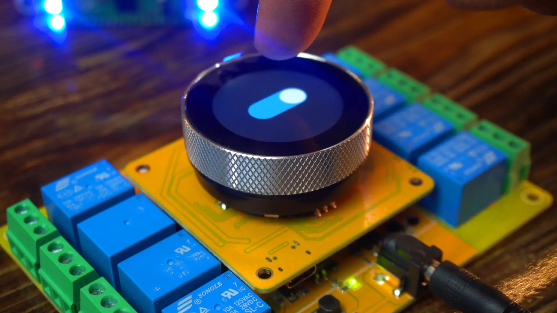
After modifying the previous template, I have put together this simple UI.
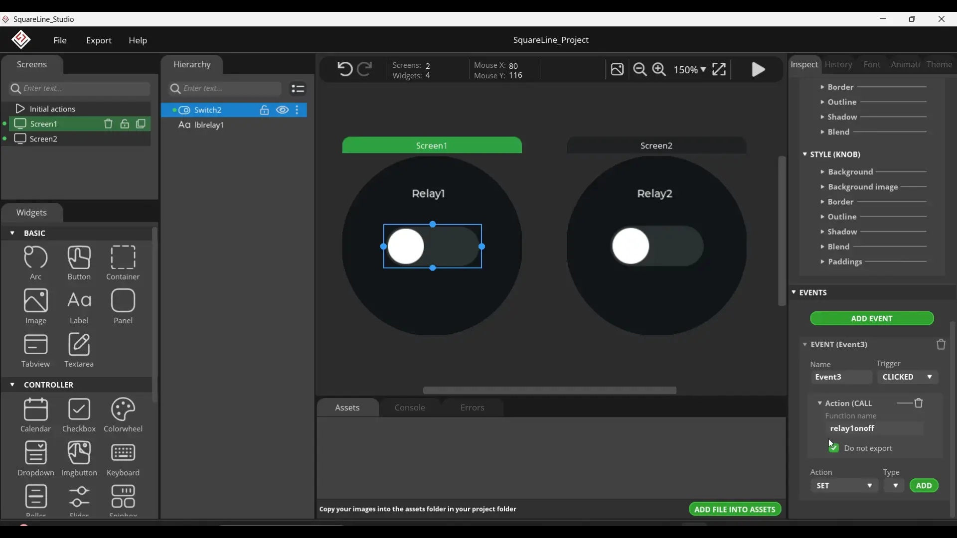
For a step-by-step walkthrough, you can read my SquareLine Studio getting-started articles. I have attached events to both switches: when I tap Switch 1, it calls relay1onoff() as you can see at the right bottom corner, and when I tap Switch 2, it calls relay2onoff(). Clean and straightforward.
Controlling Relays Code:
|
1 2 3 4 5 6 7 8 9 10 11 12 13 14 15 16 17 18 19 20 21 22 23 24 25 26 27 28 29 30 31 32 33 34 35 36 37 38 39 40 41 42 43 44 45 46 47 48 49 50 51 52 53 54 55 56 57 58 59 60 61 62 63 64 65 66 67 68 69 70 71 72 73 74 75 76 77 78 79 80 81 82 83 84 85 86 87 88 89 90 91 92 93 94 95 96 97 98 99 100 101 102 103 104 105 106 107 108 109 110 111 112 113 114 115 116 117 118 119 120 121 122 123 124 125 126 127 128 129 130 131 132 133 134 135 136 137 138 139 140 141 142 143 144 145 146 147 148 149 150 151 152 153 154 155 156 157 158 159 160 161 162 163 164 165 166 167 168 169 170 171 172 173 174 175 176 177 178 179 180 181 182 183 184 185 186 187 188 189 190 191 192 193 194 195 196 197 198 199 200 201 202 203 204 205 206 207 208 209 210 211 212 213 214 215 216 217 218 219 220 221 222 223 224 225 226 227 228 229 230 231 232 233 234 235 236 237 238 239 240 241 242 243 244 245 246 247 248 249 250 251 252 253 254 255 256 257 258 259 260 261 262 263 264 265 266 267 268 269 270 271 272 273 274 275 276 277 278 279 280 281 282 283 284 285 286 287 288 289 290 291 292 293 294 295 296 297 298 299 300 301 302 303 304 305 306 307 308 309 310 311 312 |
#include <lvgl.h> #include <Arduino_GFX_Library.h> #include "ui.h" #include <RTClib.h> #include <ESP32Time.h> #include "touch.h" #include "pin_config.h" #include "local_store.h" /*Change to your screen resolution*/ static const uint16_t screenWidth = 240; static const uint16_t screenHeight = 240; static lv_disp_draw_buf_t draw_buf; static lv_color_t buf[screenWidth * screenHeight / 10]; Arduino_ESP32SPI *bus = new Arduino_ESP32SPI(TFT_DC, TFT_CS, TFT_SCLK, TFT_MOSI, TFT_MISO, HSPI, true); // Constructor Arduino_GFX *gfx = new Arduino_GC9A01(bus, TFT_RES, 2 /* rotation */, true /* IPS */); RTC_PCF8563 rtc_pcf; ESP32Time rtc_esp; int counter = 0; int State; int old_State; int move_flag = 0; // Global int time_shift_index = 0; // hour,min,sec sequential int rtc_set_flag = 0; int page_index = 0; int alarm_set_flag = 0; int alarm_reset_flag = 0; int alarm_load_flag = 0; int alarm_store_flag = 0; int relay_flag = 0; // Switch Single Control flag int relay_state = 0; // Switching state transmit a value // Local int relay_inedx = 0; // Relay Number int relay_status[8] = {0}; // Relay status int alarm_index = 0; // Alarm Clock Number int alarm_status = 0; typedef struct My_time { int hou; int min; int sec; }; My_time t_set = {0, 0, 0}; My_time t_clock = {0, 0, 0}; My_time t_alarm = {0, 0, 0}; //8 relays, 10 sets of clocks, 6 hours, minutes, seconds + 1 end symbol '/0' char alarm_data[8][10][7]; int relay_pin[8]{ RELAY1_PIN, RELAY2_PIN, RELAY3_PIN, RELAY4_PIN, RELAY5_PIN, RELAY6_PIN, RELAY7_PIN, RELAY8_PIN}; void setup() { Serial.begin(115200); /* prepare for possible serial debug */ delay(1000); pin_init(); Wire.begin(TOUCH_SDA, TOUCH_SCL); rtc_pcf_init(); gfx->begin(); delay(200); lv_init(); lv_disp_draw_buf_init(&draw_buf, buf, NULL, screenWidth * screenHeight / 10); /*Initialize the display*/ static lv_disp_drv_t disp_drv; lv_disp_drv_init(&disp_drv); /*Change the following line to your display resolution*/ disp_drv.hor_res = screenWidth; disp_drv.ver_res = screenHeight; disp_drv.flush_cb = my_disp_flush; disp_drv.draw_buf = &draw_buf; lv_disp_drv_register(&disp_drv); /*Initialize the (dummy) input device driver*/ static lv_indev_drv_t indev_drv; lv_indev_drv_init(&indev_drv); indev_drv.type = LV_INDEV_TYPE_POINTER; indev_drv.read_cb = my_touchpad_read; lv_indev_drv_register(&indev_drv); ui_init(); Serial.println("Setup done"); xTaskCreatePinnedToCore(Task_TFT, "Task_TFT", 10240, NULL, 2, NULL, 0); // Ensure relays are OFF at startup digitalWrite(10, LOW); digitalWrite(6, LOW); // Sync switches with relay states lv_obj_clear_state(ui_Switch1, LV_STATE_CHECKED); lv_obj_clear_state(ui_Switch2, LV_STATE_CHECKED); // Bind event functions to buttons lv_obj_add_event_cb(ui_Switch1, relay1onoff, LV_EVENT_VALUE_CHANGED, NULL); lv_obj_add_event_cb(ui_Switch2, relay2onoff, LV_EVENT_VALUE_CHANGED, NULL); } long runtime = 0; void loop() { lv_timer_handler(); /* let the GUI do its work */ delay(5); } void Task_TFT(void *pvParameters) // screen refresh { while (1) { lv_timer_handler(); vTaskDelay(50); } } //--------------------------------------------- void pin_init() { pinMode(TFT_BLK, OUTPUT); digitalWrite(TFT_BLK, HIGH); pinMode(BUTTON_PIN, INPUT_PULLUP); pinMode(ENCODER_CLK, INPUT_PULLUP); pinMode(ENCODER_DT, INPUT_PULLUP); old_State = digitalRead(ENCODER_CLK); attachInterrupt(ENCODER_CLK, encoder_irq, CHANGE); for (int i = 0; i < 8; i++) { pinMode(relay_pin[i], OUTPUT); digitalWrite(relay_pin[i], 0); } } void encoder_irq() { State = digitalRead(ENCODER_CLK); if (State != old_State) { if (digitalRead(ENCODER_DT) == State) { counter++; } else { counter--; } } old_State = State; // the first position was changed } /* Display flushing */ void my_disp_flush(lv_disp_drv_t *disp, const lv_area_t *area, lv_color_t *color_p) { uint32_t w = (area->x2 - area->x1 + 1); uint32_t h = (area->y2 - area->y1 + 1); #if (LV_COLOR_16_SWAP != 0) gfx->draw16bitBeRGBBitmap(area->x1, area->y1, (uint16_t *)&color_p->full, w, h); #else gfx->draw16bitRGBBitmap(area->x1, area->y1, (uint16_t *)&color_p->full, w, h); #endif lv_disp_flush_ready(disp); } /*Read the touchpad*/ void my_touchpad_read(lv_indev_drv_t *indev_driver, lv_indev_data_t *data) { int touchX = 0, touchY = 0; if (read_touch(&touchX, &touchY) == 1) { data->state = LV_INDEV_STATE_PR; data->point.x = (uint16_t)(240 - touchX); data->point.y = (uint16_t)(240 - touchY); } else { data->state = LV_INDEV_STATE_REL; } } // UI void rtc_pcf_init() { if (!rtc_pcf.begin()) { Serial.println("Couldn't find RTC"); Serial.flush(); while (1) delay(10); } if (rtc_pcf.lostPower()) { Serial.println("PCF8563 is NOT initialized, let's set the time!"); rtc_pcf.adjust(DateTime(2024, 1, 1, 0, 0, 0)); } rtc_pcf.start(); DateTime now = rtc_pcf.now(); t_set.hou = now.hour(); t_set.min = now.minute(); t_set.sec = now.second(); char temp[40]; sprintf(temp, "PCF time %02d:%02d:%02d", t_set.hou, t_set.min, t_set.sec); Serial.println(temp); } void rtc_reset() { rtc_pcf.adjust(DateTime(2024, 1, 1, t_set.hou, t_set.min, t_set.sec)); DateTime now = rtc_pcf.now(); Serial.print(now.hour(), DEC); Serial.print(':'); Serial.print(now.minute(), DEC); Serial.print(':'); Serial.print(now.second(), DEC); Serial.println(); rtc_esp.setTime(now.second(), now.minute(), now.hour(), 25, 8, 2025); // 17th Jan 2021 1:2:3 // Serial.println(rtc_esp.getTime("%A, %B %d %Y %H:%M:%S")); Serial.println(rtc_esp.getTime()); // (String) 15:24:38 } // Relay Switch Events void relay1onoff(lv_event_t *e) { lv_event_code_t code = lv_event_get_code(e); if (code == LV_EVENT_VALUE_CHANGED) { if (lv_obj_has_state(ui_Switch1, LV_STATE_CHECKED)) { digitalWrite(10, HIGH); // Relay2 ON Serial.println("Relay2 ON"); } else { digitalWrite(10, LOW); // Relay2 OFF Serial.println("Relay2 OFF"); } } } void relay2onoff(lv_event_t *e) { lv_event_code_t code = lv_event_get_code(e); if (code == LV_EVENT_VALUE_CHANGED) { if (lv_obj_has_state(ui_Switch2, LV_STATE_CHECKED)) { digitalWrite(6, HIGH); // Relay1 ON Serial.println("Relay1 ON"); } else { digitalWrite(6, LOW); // Relay1 OFF Serial.println("Relay1 OFF"); } } } |
You will find all the pin definitions inside the pin_config.h file.
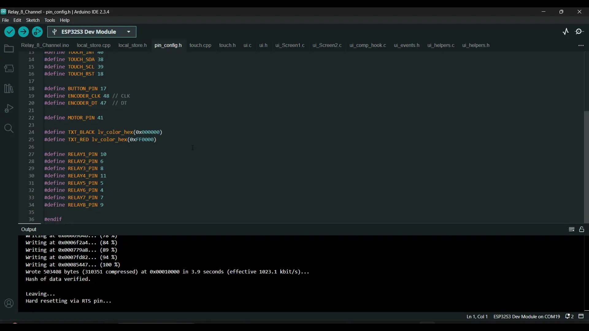
As you can see, Relay 1 and Relay 2 are connected to GPIO 10 and GPIO 6 of the ESP32-S3.
Any functions you create in SquareLine Studio will appear in the ui_events.h file.

I have used the same functions in the main .ino file to control the relays.
|
1 2 3 4 5 6 7 8 9 10 11 12 13 14 15 16 17 18 19 20 21 22 23 24 25 26 27 28 29 30 31 32 33 34 35 36 |
// Relay Switch Events void relay1onoff(lv_event_t *e) { lv_event_code_t code = lv_event_get_code(e); if (code == LV_EVENT_VALUE_CHANGED) { if (lv_obj_has_state(ui_Switch1, LV_STATE_CHECKED)) { digitalWrite(10, HIGH); // Relay2 ON Serial.println("Relay2 ON"); } else { digitalWrite(10, LOW); // Relay2 OFF Serial.println("Relay2 OFF"); } } } void relay2onoff(lv_event_t *e) { lv_event_code_t code = lv_event_get_code(e); if (code == LV_EVENT_VALUE_CHANGED) { if (lv_obj_has_state(ui_Switch2, LV_STATE_CHECKED)) { digitalWrite(6, HIGH); // Relay1 ON Serial.println("Relay1 ON"); } else { digitalWrite(6, LOW); // Relay1 OFF Serial.println("Relay1 OFF"); } } } |
You can follow the same approach to control additional relays as well.
In my previous projects, I have also demonstrated how to control and monitor devices at intermediate and advanced levels. Anyway, I have already uploaded this program; now let’s see it in action.
Practical Demonstration:
I have placed one switch on Screen1 and another on Screen2. In the same way, you can add multiple screens and use separate switches on each one; or, if you prefer, you can place multiple switches on a single screen. In fact, you can even control all relays from just one button on a single screen. I will explain this in detail in the final example.
Watch the video tutorial; to see everything in action. You will be able to hear the relays clicking sound and you will also see the onboard indicator LEDs go ON and OFF as I turn ON and turn OFF the switches.
Next, let’s move on to the encoder and display its value directly on the screen.
Reading the Encoder:
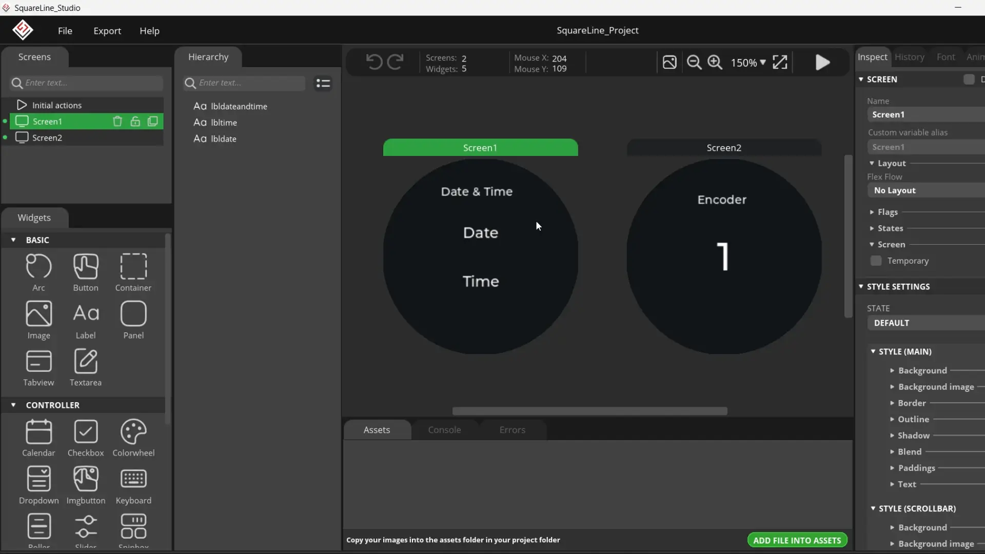
I have once again modified the template project, and this time on Screen1, I will be displaying the Date and Time. I have already written several articles on digital and analog watches, so for the basics you can check those out; because repeating the same things again and again can get a bit boring. On Screen2, we will be display the encoder value.
If you need the complete project folder, it’s available on my Patreon page.
ESPS32-S3 Encoder programming:
|
1 2 3 4 5 6 7 8 9 10 11 12 13 14 15 16 17 18 19 20 21 22 23 24 25 26 27 28 29 30 31 32 33 34 35 36 37 38 39 40 41 42 43 44 45 46 47 48 49 50 51 52 53 54 55 56 57 58 59 60 61 62 63 64 65 66 67 68 69 70 71 72 73 74 75 76 77 78 79 80 81 82 83 84 85 86 87 88 89 90 91 92 93 94 95 96 97 98 99 100 101 102 103 104 105 106 107 108 109 110 111 112 113 114 115 116 117 118 119 120 121 122 123 124 125 126 127 128 129 130 131 132 133 134 135 136 137 138 139 140 141 142 143 144 145 146 147 148 149 150 151 152 153 154 155 156 157 158 159 160 161 162 163 164 165 166 167 168 169 170 171 172 173 174 175 176 177 178 179 180 181 182 183 184 185 186 187 188 189 190 191 192 193 194 195 196 197 198 199 200 201 202 203 204 205 206 207 208 209 210 211 212 213 214 215 |
#include <lvgl.h> #include <Arduino_GFX_Library.h> #include "ui.h" #include <RTClib.h> #include <ESP32Time.h> #include "touch.h" #include "pin_config.h" #include "local_store.h" /*Change to your screen resolution*/ static const uint16_t screenWidth = 240; static const uint16_t screenHeight = 240; static lv_disp_draw_buf_t draw_buf; static lv_color_t buf[screenWidth * screenHeight / 10]; Arduino_ESP32SPI *bus = new Arduino_ESP32SPI(TFT_DC, TFT_CS, TFT_SCLK, TFT_MOSI, TFT_MISO, HSPI, true); Arduino_GFX *gfx = new Arduino_GC9A01(bus, TFT_RES, 2 /* rotation */, true /* IPS */); RTC_PCF8563 rtc_pcf; ESP32Time rtc_esp; volatile int counter = 0; int State; int old_State; /* ================== SETUP =================== */ void setup() { Serial.begin(115200); delay(1000); pin_init(); Wire.begin(TOUCH_SDA, TOUCH_SCL); rtc_pcf_init(); rtc_reset(); // <--- This will apply your custom variables gfx->begin(); delay(200); lv_init(); lv_disp_draw_buf_init(&draw_buf, buf, NULL, screenWidth * screenHeight / 10); static lv_disp_drv_t disp_drv; lv_disp_drv_init(&disp_drv); disp_drv.hor_res = screenWidth; disp_drv.ver_res = screenHeight; disp_drv.flush_cb = my_disp_flush; disp_drv.draw_buf = &draw_buf; lv_disp_drv_register(&disp_drv); static lv_indev_drv_t indev_drv; lv_indev_drv_init(&indev_drv); indev_drv.type = LV_INDEV_TYPE_POINTER; indev_drv.read_cb = my_touchpad_read; lv_indev_drv_register(&indev_drv); ui_init(); Serial.println("Setup done"); xTaskCreatePinnedToCore(Task_TFT, "Task_TFT", 10240, NULL, 2, NULL, 0); // Create LVGL timers for updating labels lv_timer_create(update_datetime, 1000, NULL); // every 1 sec lv_timer_create(update_encoder, 200, NULL); // every 200 ms } /* ================== LOOP =================== */ void loop() { lv_timer_handler(); delay(5); } void Task_TFT(void *pvParameters) { while (1) { lv_timer_handler(); vTaskDelay(50); } } /* ================== PIN INIT =================== */ void pin_init() { pinMode(TFT_BLK, OUTPUT); digitalWrite(TFT_BLK, HIGH); pinMode(BUTTON_PIN, INPUT_PULLUP); pinMode(ENCODER_CLK, INPUT_PULLUP); pinMode(ENCODER_DT, INPUT_PULLUP); old_State = digitalRead(ENCODER_CLK); attachInterrupt(ENCODER_CLK, encoder_irq, CHANGE); } void encoder_irq() { State = digitalRead(ENCODER_CLK); if (State != old_State) { if (digitalRead(ENCODER_DT) == State) { counter++; } else { counter--; } } old_State = State; } /* ================== DISPLAY =================== */ void my_disp_flush(lv_disp_drv_t *disp, const lv_area_t *area, lv_color_t *color_p) { uint32_t w = (area->x2 - area->x1 + 1); uint32_t h = (area->y2 - area->y1 + 1); #if (LV_COLOR_16_SWAP != 0) gfx->draw16bitBeRGBBitmap(area->x1, area->y1, (uint16_t *)&color_p->full, w, h); #else gfx->draw16bitRGBBitmap(area->x1, area->y1, (uint16_t *)&color_p->full, w, h); #endif lv_disp_flush_ready(disp); } /* ================== TOUCH =================== */ void my_touchpad_read(lv_indev_drv_t *indev_driver, lv_indev_data_t *data) { int touchX = 0, touchY = 0; if (read_touch(&touchX, &touchY) == 1) { data->state = LV_INDEV_STATE_PR; data->point.x = (uint16_t)(240 - touchX); data->point.y = (uint16_t)(240 - touchY); } else { data->state = LV_INDEV_STATE_REL; } } // ================== USER DATE/TIME SETTINGS ================== int setYear = 2025; int setMonth = 9; // September int setDay = 6; int setHour = 14; // 2 PM int setMinute = 30; int setSecond = 0; void rtc_pcf_init() { if (!rtc_pcf.begin()) { Serial.println("Couldn't find RTC"); while (1) delay(10); } if (rtc_pcf.lostPower()) { Serial.println("PCF8563 not initialized, will set default later."); // don’t adjust here – rtc_reset() will handle it } rtc_pcf.start(); } void rtc_reset() { rtc_pcf.adjust(DateTime(setYear, setMonth, setDay, setHour, setMinute, setSecond)); DateTime now = rtc_pcf.now(); Serial.printf("RTC Updated: %04d/%02d/%02d %02d:%02d:%02d\n", now.year(), now.month(), now.day(), now.hour(), now.minute(), now.second()); rtc_esp.setTime(now.second(), now.minute(), now.hour(), now.day(), now.month(), now.year()); } /* ================== UPDATERS =================== */ void update_datetime(lv_timer_t * timer) { DateTime now = rtc_pcf.now(); char bufTime[16]; sprintf(bufTime, "%02d:%02d:%02d", now.hour(), now.minute(), now.second()); lv_label_set_text(ui_lbltime, bufTime); char bufDate[16]; sprintf(bufDate, "%02d/%02d/%04d", now.day(), now.month(), now.year()); lv_label_set_text(ui_lbldate, bufDate); } void update_encoder(lv_timer_t * timer) { char buf[16]; sprintf(buf, "%d", counter); lv_label_set_text(ui_lblencodervalue, buf); } |
Practical demonstration:

On Screen1, you can clearly see the exact date and time. In the programming, I have defined variables for this, so you can easily set any custom date and time you like.
|
1 2 3 4 5 6 7 |
// ================== USER DATE/TIME SETTINGS ================== int setYear = 2025; int setMonth = 9; // September int setDay = 6; int setHour = 14; // 2 PM int setMinute = 30; int setSecond = 0; |
And the best part is; you only need to do this once. Since the board already has an RTC with a battery, the date and time won’t reset even if you cut the power. If you want to update the date and time at runtime, I have already written quite a detailed article on this as well.
Now, when I swipe my finger to the left, it takes me to Screen2 where I can monitor the encoder value.
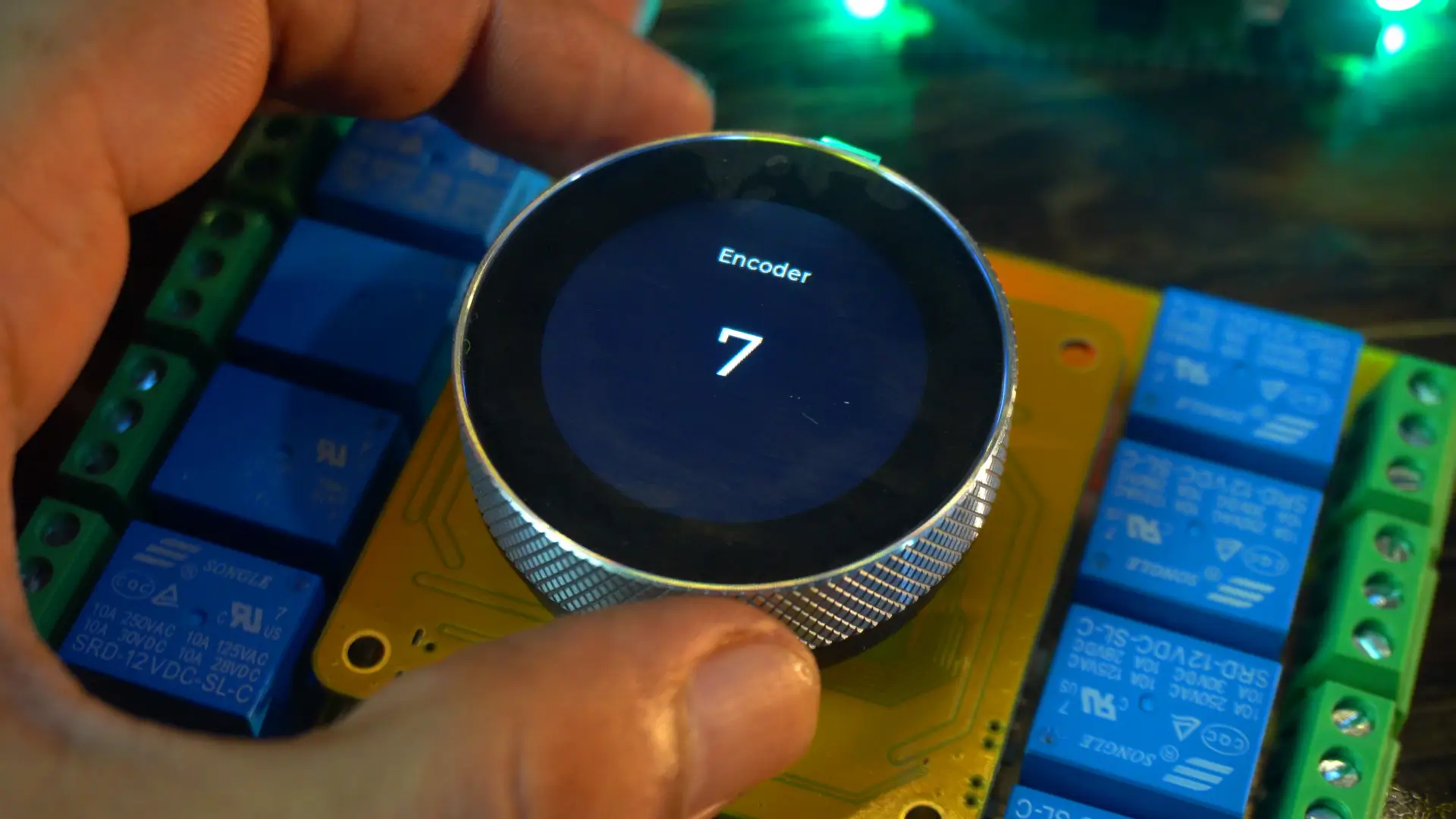
As I rotate the encoder clockwise, the value increments, and when I rotate it counter-clockwise, the value decrements.
Controlling Relays using Encoder and a Button:
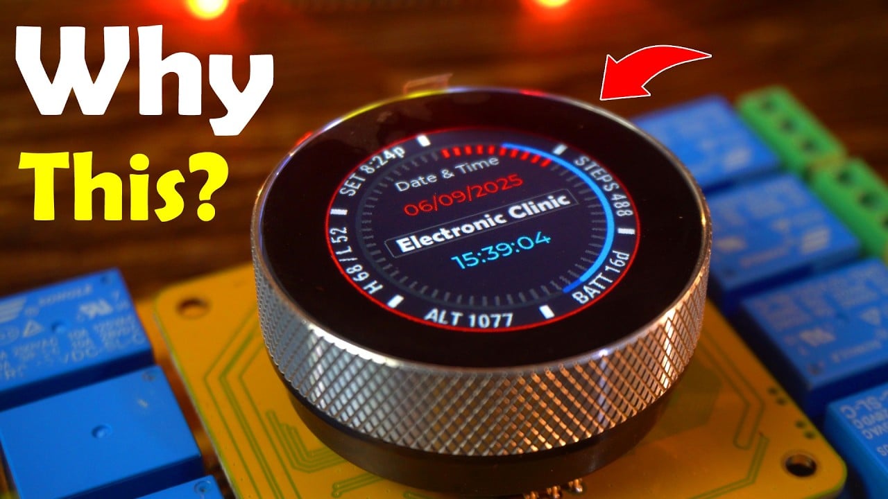
To make the design look a little more attractive, I have used this background image, which I designed in Photoshop.

This is just to show you how easily you can improve your UI with a simple background image. As you can see, I am still using the same labels; only now it looks more professional.
Controlling relays using Encoder and a button Program:
|
1 2 3 4 5 6 7 8 9 10 11 12 13 14 15 16 17 18 19 20 21 22 23 24 25 26 27 28 29 30 31 32 33 34 35 36 37 38 39 40 41 42 43 44 45 46 47 48 49 50 51 52 53 54 55 56 57 58 59 60 61 62 63 64 65 66 67 68 69 70 71 72 73 74 75 76 77 78 79 80 81 82 83 84 85 86 87 88 89 90 91 92 93 94 95 96 97 98 99 100 101 102 103 104 105 106 107 108 109 110 111 112 113 114 115 116 117 118 119 120 121 122 123 124 125 126 127 128 129 130 131 132 133 134 135 136 137 138 139 140 141 142 143 144 145 146 147 148 149 150 151 152 153 154 155 156 157 158 159 160 161 162 163 164 165 166 167 168 169 170 171 172 173 174 175 176 177 178 179 180 181 182 183 184 185 186 187 188 189 190 191 192 193 194 195 196 197 198 199 200 201 202 203 204 205 206 207 208 209 210 211 212 213 214 215 216 217 218 219 220 221 222 223 224 225 226 227 228 229 230 231 232 233 234 235 236 237 238 239 240 241 242 243 244 245 246 247 248 249 250 251 252 253 254 |
#include <lvgl.h> #include <Arduino_GFX_Library.h> #include "ui.h" #include <RTClib.h> #include <ESP32Time.h> #include "touch.h" #include "pin_config.h" #include "local_store.h" /*Change to your screen resolution*/ static const uint16_t screenWidth = 240; static const uint16_t screenHeight = 240; static lv_disp_draw_buf_t draw_buf; static lv_color_t buf[screenWidth * screenHeight / 10]; Arduino_ESP32SPI *bus = new Arduino_ESP32SPI(TFT_DC, TFT_CS, TFT_SCLK, TFT_MOSI, TFT_MISO, HSPI, true); Arduino_GFX *gfx = new Arduino_GC9A01(bus, TFT_RES, 2 /* rotation */, true /* IPS */); RTC_PCF8563 rtc_pcf; ESP32Time rtc_esp; volatile int counter = 0; int State; int old_State; int relayPins[8] = {RELAY1_PIN, RELAY2_PIN, RELAY3_PIN, RELAY4_PIN, RELAY5_PIN, RELAY6_PIN, RELAY7_PIN, RELAY8_PIN}; int relayState[8] = {0}; // OFF=0, ON=1 /* ================== SETUP =================== */ void setup() { Serial.begin(115200); delay(1000); pin_init(); Wire.begin(TOUCH_SDA, TOUCH_SCL); rtc_pcf_init(); rtc_reset(); gfx->begin(); delay(200); lv_init(); lv_disp_draw_buf_init(&draw_buf, buf, NULL, screenWidth * screenHeight / 10); static lv_disp_drv_t disp_drv; lv_disp_drv_init(&disp_drv); disp_drv.hor_res = screenWidth; disp_drv.ver_res = screenHeight; disp_drv.flush_cb = my_disp_flush; disp_drv.draw_buf = &draw_buf; lv_disp_drv_register(&disp_drv); static lv_indev_drv_t indev_drv; lv_indev_drv_init(&indev_drv); indev_drv.type = LV_INDEV_TYPE_POINTER; indev_drv.read_cb = my_touchpad_read; lv_indev_drv_register(&indev_drv); ui_init(); Serial.println("Setup done"); xTaskCreatePinnedToCore(Task_TFT, "Task_TFT", 10240, NULL, 2, NULL, 0); // Create LVGL timers for updating labels lv_timer_create(update_datetime, 1000, NULL); // every 1 sec lv_timer_create(update_encoder, 200, NULL); // every 200 ms } /* ================== LOOP =================== */ void loop() { lv_timer_handler(); delay(5); } void Task_TFT(void *pvParameters) { while (1) { lv_timer_handler(); vTaskDelay(50); } } /* ================== PIN INIT =================== */ void pin_init() { pinMode(TFT_BLK, OUTPUT); digitalWrite(TFT_BLK, HIGH); // Relays for (int i = 0; i < 8; i++) { pinMode(relayPins[i], OUTPUT); digitalWrite(relayPins[i], LOW); } pinMode(BUTTON_PIN, INPUT_PULLUP); // Encoder pinMode(ENCODER_CLK, INPUT_PULLUP); pinMode(ENCODER_DT, INPUT_PULLUP); old_State = digitalRead(ENCODER_CLK); attachInterrupt(ENCODER_CLK, encoder_irq, CHANGE); } void encoder_irq() { State = digitalRead(ENCODER_CLK); if (State != old_State) { if (digitalRead(ENCODER_DT) == State) { counter++; } else { counter--; } } old_State = State; } /* ================== DISPLAY =================== */ void my_disp_flush(lv_disp_drv_t *disp, const lv_area_t *area, lv_color_t *color_p) { uint32_t w = (area->x2 - area->x1 + 1); uint32_t h = (area->y2 - area->y1 + 1); #if (LV_COLOR_16_SWAP != 0) gfx->draw16bitBeRGBBitmap(area->x1, area->y1, (uint16_t *)&color_p->full, w, h); #else gfx->draw16bitRGBBitmap(area->x1, area->y1, (uint16_t *)&color_p->full, w, h); #endif lv_disp_flush_ready(disp); } /* ================== TOUCH =================== */ void my_touchpad_read(lv_indev_drv_t *indev_driver, lv_indev_data_t *data) { int touchX = 0, touchY = 0; if (read_touch(&touchX, &touchY) == 1) { data->state = LV_INDEV_STATE_PR; data->point.x = (uint16_t)(240 - touchX); data->point.y = (uint16_t)(240 - touchY); } else { data->state = LV_INDEV_STATE_REL; } } // ================== USER DATE/TIME SETTINGS ================== int setYear = 2025; int setMonth = 9; // September int setDay = 6; // 1st int setHour = 15; // 2 PM int setMinute = 30; int setSecond = 0; void rtc_pcf_init() { if (!rtc_pcf.begin()) { Serial.println("Couldn't find RTC"); while (1) delay(10); } if (rtc_pcf.lostPower()) { Serial.println("PCF8563 not initialized, will set default later."); // don’t adjust here – rtc_reset() will handle it } rtc_pcf.start(); } void rtc_reset() { rtc_pcf.adjust(DateTime(setYear, setMonth, setDay, setHour, setMinute, setSecond)); DateTime now = rtc_pcf.now(); Serial.printf("RTC Updated: %04d/%02d/%02d %02d:%02d:%02d\n", now.year(), now.month(), now.day(), now.hour(), now.minute(), now.second()); rtc_esp.setTime(now.second(), now.minute(), now.hour(), now.day(), now.month(), now.year()); } /* ================== UPDATERS =================== */ void update_datetime(lv_timer_t * timer) { DateTime now = rtc_pcf.now(); char bufTime[16]; sprintf(bufTime, "%02d:%02d:%02d", now.hour(), now.minute(), now.second()); lv_label_set_text(ui_lbltime, bufTime); char bufDate[16]; sprintf(bufDate, "%02d/%02d/%04d", now.day(), now.month(), now.year()); lv_label_set_text(ui_lbldate, bufDate); } void update_encoder(lv_timer_t * timer) { // Keep encoder in range [0..7] if (counter < 0) counter = 0; if (counter > 7) counter = 7; // Show current relay number char buf[8]; sprintf(buf, "%d", counter + 1); lv_label_set_text(ui_lblencodervalue, buf); // --- NEW: always show relay status when scrolling --- char statusText[20]; sprintf(statusText, "Relay%d %s", counter + 1, relayState[counter] ? "ON" : "OFF"); lv_label_set_text(ui_lblrelay, statusText); // Handle button press (toggle relay) static int lastButton = HIGH; int buttonState = digitalRead(BUTTON_PIN); if (lastButton == HIGH && buttonState == LOW) { // falling edge = press relayState[counter] = !relayState[counter]; digitalWrite(relayPins[counter], relayState[counter]); // Update text immediately after toggle sprintf(statusText, "Relay%d %s", counter + 1, relayState[counter] ? "ON" : "OFF"); lv_label_set_text(ui_lblrelay, statusText); Serial.println(statusText); } lastButton = buttonState; } |
In the code, I have already made all the necessary changes. Once you read through it, you will understand the idea.
If you want complete project source codes and resources, you can download them from my Patreon page.
Practical Demonstration:

Even though I am not a graphics designer, just adding this simple background makes the display come alive. If you have good graphics designing skills, you can create even more amazing backgrounds; and yes, you can even animate them. I have already demonstrated this in my analog watch tutorials.
So, let’s go to Screen 2.

By default, you will see Relay1 OFF, because right now it’s OFF. If it were ON, you would see Relay1 ON.
The controller not only reads the relay status, but it also remembers the state.
Let’s go ahead and turn it ON.

Now, the status has changed from OFF to ON.
Next, I check all the relays, and it worked exceptionally well. I was also able to check the status of each and every relay. There was no confusion at all.
6 more projects are coming up next, so don’t forget to subscribe.
So, that’s all for now.
Watch Video Tutorial:
Discover more from Electronic Clinic
Subscribe to get the latest posts sent to your email.


