ESP32 Ubidots IoT Project, Two-way Communication
Last Updated on January 19, 2025 by Engr. Shahzada Fahad
Table of Contents
ESP32 Ubidots IoT Project:
ESP32 Ubidots IoT Project, Two-way Communication– In today’s article, we are diving into something super exciting; two-way communication between Ubidots and the ESP32! Imagine not just sending data from your ESP32 to the cloud, but also controlling your devices remotely, all in real-time.

It’s been 5 years since I last used the Ubidots IoT platform. I got busy with other projects, and over time, I completely forgot about Ubidots. But recently, I had to work on an IoT project that was pretty complex.
First, I tried it on Blynk, then on some other IoT platforms I remembered, but none of them worked.
So, I started checking my old IoT projects to see which platforms I had used before. Honestly, in these 5 years, I worked on so many IoT platforms that I even forgot the names of some.
While going through my projects, I came across Ubidots, and I immediately felt that the idea I wanted to implement could work 100% on it.
As an experiment, I tried one of my old projects, but I was shocked because every time I tried to compile the code, I got errors. Then I thought, “It’s been 5 years; maybe a lot has changed.” And I was right; so much had changed over the years. Anyway, I successfully completed that project. And I also decided to write this “getting started” article to help others who might be struggling to compile their old codes or run new ones.
So, without any further delay, let’s get started!!!
Amazon Links:
ESP32 WiFi + Bluetooth Module (Recommended)
Other Tools and Components:
Arduino Nano USB C type (Recommended)
*Please Note: These are affiliate links. I may make a commission if you buy the components through these links. I would appreciate your support in this way!
About the Hardware:

I am going to use this ESP32 development board. This is the same development board I used with the SIM7600G 4G LTE module. In that article, I explained the circuit diagram and its assembly, so make sure to read it. The reason I selected this development board is that it already has a relay, which I am going to use to control a 110/220Vac bulb. For the relay connections, you can follow this circuit diagram.
Relay interfacing with ESP32:

Required Libraries for the Ubidots:
First, download these two libraries from the Ubidots official website.

Then, open the latest version of the Arduino IDE. Before installing the required libraries, you need to first install the ESP32 board in the Arduino IDE. To do this:
- Go to the File menu and then to Preferences.
- Copy the link given below and paste it into the Additional Boards Manager URLs.
Boards Manager URL:
|
1 |
https://raw.githubusercontent.com/espressif/arduino-esp32/gh-pages/package_esp32_index.json |

Next, click on the Boards Manager and search for “ESP32.”

Make sure to install the one by Espressif Systems. As you can see, I have already installed it.
To verify that the ESP32 board is installed in the Arduino IDE:
- Go to the Tools menu.
- Navigate to Board, then ESP32, and you will see all the variants of the ESP32.

The one I am using is the ESP32 Dev Module. If you are using a different ESP32 board, simply select it from the list.
Finally, go ahead and install the required libraries. I am sure you know how to install the libraries, if not then you can watch the video at the end of this article.
Now, let’s move on and work with Ubidots.
Ubidots Dashboard:
While you are logged-in into your Ubidots account. Go to the Data Menu and then click on the Dashboards.

On the left side, you can see these 3 lines, click on those three lines next to the New Dashboard.
Click the CREATE button to add a new Dashboard.
Let’s name it Home Automation, let’s keep everything else to their default values. Once you learn the basics, then you can come back and play with all these properties. Anyway, let’s click the SAVE button.

Our Home Automation Dashboard is ready.

Now, go to the Devices Menu and click on Devices.
Click the + button to create a new device.
Click on Blank Device.
Now, go to the Arduino program and copy the DEVICE_LABEL “home_automation” and paste it in the two boxes. The device label should exactly match the DEVICE_LABEL set in the Arduino code. Once the Device name and Device label are set then click the NEXT button.

You can see a new device with the name home_automation has been created.

Let’s open this device.

Right now there are 0 Variables, because I have not yet uploaded the program into the ESP32. Because I needed this Token. So, let’s copy this Token and paste it in the program next to the UBIDOTS_TOKEN.
ESP32 Ubidots Programming:
|
1 2 3 4 5 6 7 8 9 10 11 12 13 14 15 16 17 18 19 20 21 22 23 24 25 26 27 28 29 30 31 32 33 34 35 36 37 38 39 40 41 42 43 44 45 46 47 48 49 50 51 52 53 54 55 56 57 58 59 60 61 62 63 64 65 66 67 68 69 70 71 72 73 74 75 76 77 78 79 80 81 82 83 84 85 86 87 88 89 90 91 92 93 94 95 96 97 98 99 100 101 102 103 104 105 106 107 108 |
#include "UbidotsEsp32Mqtt.h" /**************************************** * Define Constants ****************************************/ const char *UBIDOTS_TOKEN = "BBUS-rjGu5ma4LL0JqclAPoheYt2IM2MvgN"; // Put here your Ubidots TOKEN const char *WIFI_SSID = "fahad"; // Put here your Wi-Fi SSID const char *WIFI_PASS = "fahad123"; // Put here your Wi-Fi password const char *DEVICE_LABEL = "home_automation"; // Put here your Device label to which data will be published const char *VARIABLE_LABEL = "counter"; // Counter value const char *VARIABLE_LABEL2 = "relay1"; // to control the relay const int PUBLISH_FREQUENCY = 5000; // Update rate in milliseconds unsigned long timer; uint8_t analogPin = 34; // Pin used to read data from GPIO34 ADC_CH6. float value=0; // To store incoming value. int Relay1 = 13; int counter = 0; Ubidots ubidots(UBIDOTS_TOKEN); /**************************************** * Auxiliar Functions ****************************************/ // cast from an array of chars to float value. float btof(byte * payload, unsigned int length) { char * demo = (char *) malloc(sizeof(char) * 10); for (int i = 0; i < length; i++) { demo[i] = payload[i]; } float value = atof(demo); free(demo); return value; } // Callback to handle subscription void callback(char* topic, byte* payload, unsigned int length) { value = btof(payload, length); Serial.println(value); if (value == 0.00) { Serial.println("Light1 turned off"); digitalWrite(Relay1, LOW); } if (value == 1.00) { Serial.println("Light1 turned ON"); digitalWrite(Relay1, HIGH); } } /**************************************** * Main Functions ****************************************/ void setup() { // put your setup code here, to run once: Serial.begin(115200); // ubidots.setDebug(true); // uncomment this to make debug messages available ubidots.connectToWifi(WIFI_SSID, WIFI_PASS); ubidots.setCallback(callback); ubidots.setup(); ubidots.reconnect(); timer = millis(); ubidots.subscribeLastValue(DEVICE_LABEL, VARIABLE_LABEL2); // Insert the dataSource and Variable's Labels pinMode(Relay1, OUTPUT); } void loop() { // put your main code here, to run repeatedly: if (!ubidots.connected()) { ubidots.reconnect(); ubidots.subscribeLastValue(DEVICE_LABEL, VARIABLE_LABEL2); // Insert the dataSource and Variable's Labels } if ((millis() - timer) > PUBLISH_FREQUENCY) // triggers the routine every 5 seconds { float value = analogRead(analogPin); ubidots.add(VARIABLE_LABEL, counter); // Insert your variable Labels and the value to be sent ubidots.publish(DEVICE_LABEL); timer = millis(); counter++; if (counter == 40) { counter = 0; } } ubidots.loop(); } |
Upload the program and then go back to the Ubidots and refresh the page.

Now, you can see the counter variable. Let’s also create a variable for controlling the relay. For this go back to the Arduino IDE and copy this “relay1”.
Click on the + button to add a new variable and paste the text “relay1”.

The two variables counter and Relay1 are ready.
Now, go to the Data menu and click on the Dashboards.
While the Home Automation Dashboard is selected, click on Add new Widget to add a new widget or you can also click this + Button at the top right corner.

You will see so many widgets, for now you can add a Gauge for displaying the counter value.
Click on the + ADD VARIABLES.
Click on the home_automation.

You can see the two variables, since we want to display the counter value on the Gauge, so we are going to select the counter variable.

On the APPERANCE tab, you can name the Gauge Widget, you can change the font, and most importantly you can specify the range. For now 0 to 100 range looks just fine. Once you are done with the settings; click the SAVE button.
Now, let’s add a switch for controlling a Relay. The steps are exactly the same.

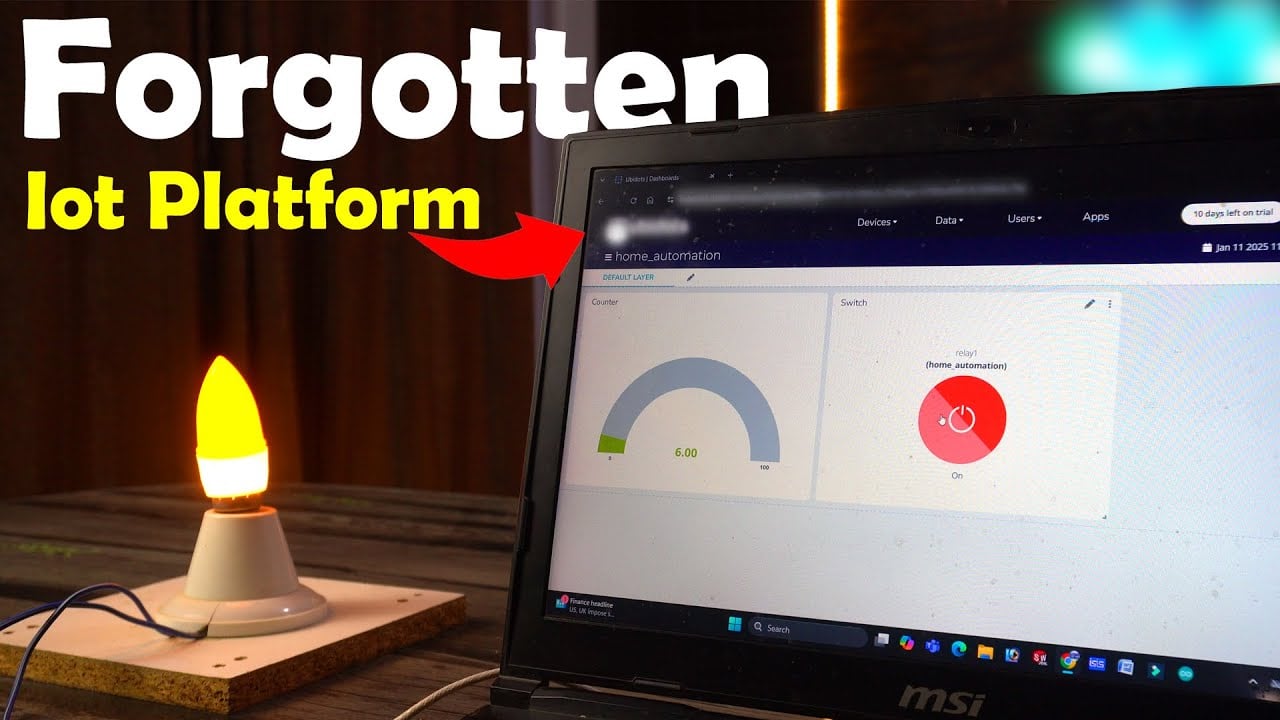
Our dashboard is now ready, and it’s looking great! You can already see the counter value displayed in real-time on the Gauge; it updates instantly, giving you live data feedback.

But that’s not all! Check out this button right here; it’s not just for show. With a single click, we can control the relay, turning it on or off with ease.

Imagine the possibilities! Using this dashboard, you are not limited to just one application.

You can monitor sensor data like temperature, humidity, or motion, and at the same time, control different types of loads;

Be it lights, fans, or even appliances right from your phone or computer. And the best part? You can do all of this from anywhere in the world!
Whether you are sitting at home, traveling, or even halfway across the globe, this dashboard keeps you connected and in control. How cool is that?
So, that’s all for now.
Watch Video Tutorial:
Discover more from Electronic Clinic
Subscribe to get the latest posts sent to your email.


