Introduction of Cleat Wiring System
Cleat wiring system: Advantages, Disadvantages and uses of Cleat Wiring
Last Updated on August 20, 2022 by Engr. Shahzada Fahad
Table of Contents
Introduction
Cleat wiring system- Installation means the act of installing something. Connecting two things or recombining two things in such a specific configuration or sequence that a complete system builds as a result of their joining or conjugation, is called installation. Electrical installation means the provision of corresponding supply to electrical appliances or instruments and their induction together with the safety circuits. The electrical installation provides a safe source for connecting electrical appliances of a consumer with electrical supply through over current and earth leakage protection. It consists of all cables, pertinent safety components, and control gear. In short, fixing different types of circuits and electrical equipment on a panel, recombination of electrical components with an incomplete system for making a complete system thereof, installation of electrical wiring in a precise or correct fashion either temporarily or permanently, installation of protective gadgets, installation of service lines on a one floor or multi-floor buildings, installation of motors, installation of load and earthing system are all included in electrical installation. In fact, the electrical installation consists of a complete system of all types of electrical wiring and its associated electrical components or instruments, protection, testing, signal communication circuits, and entire instruments related to the electrical control, installed in residential and commercial buildings, industrial units, factories, and refineries, etc.
Wiring Systems
The following wiring systems or methods are used:
- Cleat Wiring System
- Batten Wiring System
- Casing Capping Wiring System
- Conduit Wiring System
Conduit wiring may further be classified into the following two types
(i). Surface Conduit Wiring
(ii). Concealed Conduit wiring
Cleat Wiring System
A system of wiring in which wires or cables are installed on cleats made from porcelain, plastic, or hardwood, is called cleating wiring system. In other words, wiring done on porcelain, plastic, or hardwood-made cleats is called cleat wiring. This is the cheapest, simplest, and easiest form of wiring, which is most commonly used for momentary or temporary objectives. In cleat wiring, mostly VRI or single-core PVC and sometimes sheathed or weatherproof wires are being used. This wiring can be done both in vertical and horizontal directions. Remember that cleat wiring is carried out in places where there is no danger of any sort of blow to wires because wires remain exposed or open in this type of wiring system. The checking or inspection of such types of wires is relatively easy due to being in an open condition. However, the application of the cleat wiring has almost ceased nowadays.
The cleat being applied in cleat wiring consists of two segments. The lower segment is called the base whereas its upper part is called the cap. Grooves have been formed on the base, wherefrom wires are passed through and the cap is placed on the base and tightened through a screw whereas the entire cleat is screwed on a pre-fitted dowel or rowel plug on a wall at a distance of about 6 millimeters. In other words, the base or lower part of the cleat is mounted on a roof or any wall by means of tightening it through a rowel plug or dowel. Whereas the upper part of the cleat controls wires existing on grooves in the lower segment or base of the cleat, which is tightened with the lower section or base through screws. In order to install cables or wires of different types and different sizes on a cleat, cleats of numerous sizes and types are used. The cleats of 1,2 and 3 holes or grooves are commonly used in cleat wiring with respect to the number of cables. The cleats having two holes or grooves are used for single-phase 220 volts whereas cleats with 3 grooves are used for 440 volts three-phase supply. In figure 1.1, cleats with 2 and 3 grooves have been illustrated.
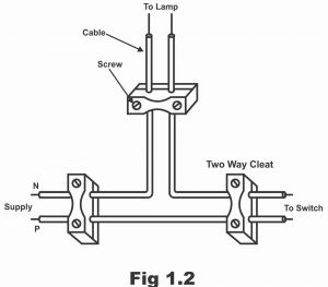
It is being ensured during cleat wiring that cables existing on cleats, do not go through excessive stress, because in this way there is a risk of cables insulation getting damaged. Moreover, it is also further ensured that no excessive sagging occurs in cables existing on a cleat. Therefore, cleats are used according to the sizes of cables. A distance of about half a meter is retained between cleats. Whereas wires existing on cleats are kept 1.5 centimeters away from the wall while the mutual distance between two wires tends to be 4 cm to 7 cm according to the current ratio. The size of screws being used in cleat wiring normally tends to be 38 mm. The size of the larger or wider end of dowels or rowel plugs is 38 mm x 38 mm whereas the size of the narrow end tends to be 25 mm x 25 mm. Whereas the length of the dowels or rowel plug tends to be around 6.5 cm. In figure 1.2, cleats have been illustrated with cables having been installed on them.
Figure 1.1 – porcelain cleat
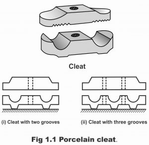
Figure 1.2
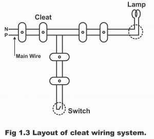
As cleat wiring can be done both in horizontal as well as the vertical direction, therefore whenever a circuit of this type of wiring is passed above another circuit, an insulator must essentially be used on lower cables, so that wires of both the circuits could be kept apart. In order to safeguard cables from any kind of damage on bends or corners, a special type of cleat is always used. Cleat wiring is temporarily used in workshops or industries for sub-circuit or sub-main wiring. If high current capacity cables are used in this type of wiring, their minimum distance from the ground should be 2.5 to 3 meters. Moreover, the earthing system should be available on switching and junction spots and only one cable must be penetrated through a single hole at the time of entering cables into junction box switchboards, etc. However, in the case of a large number of cables, there must be grooves between holes. When wires or cables are passed through the roof or walls, a porcelain tube or a metal conduit pipe is used for the purpose. In figure 1.3, a layout of cleat wiring has been illustrated.
Figure 1.3 – Layout of a cleat wiring system
Advantages of Cleat Wiring:
(1). This is a cheap and simple system of wiring
(2). Its application for temporary purposes is very appropriate. For example, in under-construction buildings or army camping, etc.
(3). It is quite easy to search for a fault and repair it quite quickly by inspecting the exposed wires.
(4). This wiring can be done quite quickly and easily
(5). This wiring can be removed or uprooted as and when required without too much material loss
(6). Alterations or additions can be done in this type of wiring during times of need
(7). Inspection of this type of wiring system is possible quite easily
(8). In case of wiring has been removed, it is possible to use its paraphernalia at some other places or for some other tasks.
(9). No expert technicians are required for this type of wiring
Disadvantages of Cleat Wiring:
(1). Cleat wiring cannot be installed for everlasting or permanent purposes, because sagging takes place in wires at several spots after the passage of some time.
(2). As cables in this type of wiring are not covered, therefore they are likely to be damaged through oil, steam, moisture, smoke, rain, and chemical and acid effects.
(3). After some time, smoke and dust build-up on wires, as a result, they present a very shabby and decrepit.
(4). This type of wiring cannot be considered enduring due to weather consequences and fire dangers.
(5). It can be used only for low temperatures 250/ 440 volts
(6). It is extremely weak mechanically and exposed to blow or concussion at any moment
(7). As this type of wiring is temporary, therefore an imminent danger of some electric shock always persists
(8). Cleat wiring entails a risk of catching fire at any moment
(9). This type of wiring cannot be used in sensitive or important places
(10). This type of wiring is neither endurable nor reliable.
Uses of Cleat Wiring:
Cleat wiring is normally used in under-construction buildings, workshops, display centers, industries, army camps, etc., and all those places where the probability of concussion or any sort of damage to wires is minimal.
Next Topic: Batten Wiring System
For electronics and programming-related projects visit my YouTube channel.
Discover more from Electronic Clinic
Subscribe to get the latest posts sent to your email.


Great…..
One of the best & very briefly define this CLEAT WIRING.
Thank you Engr. Shahzada FAHAD.
thank you so much
This introduction to the Cleat Wiring System was really enlightening! I appreciate how you broke down the components and their significance. Looking forward to learning more about practical applications in the upcoming posts!