Methods of Testing Electrical Installations
Last Updated on August 20, 2023 by Engr. Shahzada Fahad
Table of Contents
Methods of Testing Electrical Installations
After the completion of the wiring and before connecting it permanently to the supply, it must be ensured that no such fault or defect exists in the wiring, which may cause financial or physical damage to the consumer. It is also essential to verify that wiring work has been completed according to the standard electricity rules. Electricity rules 1973 applies to all types of wiring, according to which insulation of wire going to be used for wiring should be satisfactory so that no corporeal or material loss occurs. For this purpose, a test report is prepared after the conduction of several tests, without provision of which, the supply company (WAPDA) does not provide a connection to the consumer.
The following methods are generally being used for the testing of electrical installations;
- Polarity testing of electrical installations
- Continuity testing of electrical installations
- Continuity Test of Earth Connection
- Insulation Test testing of electrical installations or Leakage testing of electrical installations
- Short Circuit testing of electrical installations
- Earth Resistance testing of electrical installations
Polarity testing of electrical installations
A test in which the existence of phase on all switches is checked is known as a polarity test. According to electricity rule 51, in single-phase wiring installations, all single pole switches must be fitted on phase or live wire (i.e., on a series of phase wires), so that whenever a switch is turned off, the lamp or fan, etc. controlled through that switch immediately disconnects completely from the phase supply. To verify whether all single pole switches have been installed on the phase wire or not, a polarity test is conducted. If switches have been fitted along a neutral wire instead of phase wire, in such a situation electrical installations (e.g., lamp holders or fans, etc.) become a part of the wiring and it remains energized (direct phase supply continues within it) even if its switch is turned ON or OFF. As a result, a person who touches it may face a life threat as a result of some electric shock. As such, from a safety point of view, single-phase switches should always be fitted along a phase wire instead of a neutral wire. It should be remembered that apart from single phase switches, this electricity rule also applies to fuses as well as circuit breakers. Moreover, a correct connection of the socket-outlet is also examined through this test. That’s if we look at the socket outlet from the front, the phase is on the right, neutral on the left, and in the case of a three-pin socket, the earth is on the top.
The polarity test is undertaken through the following three methods;
(i). Polarity Test by a Test Lamp
(ii). Polarity Test by Megger
(iii). Polarity Test by Continuity Tester
Polarity Test by a Test Lamp
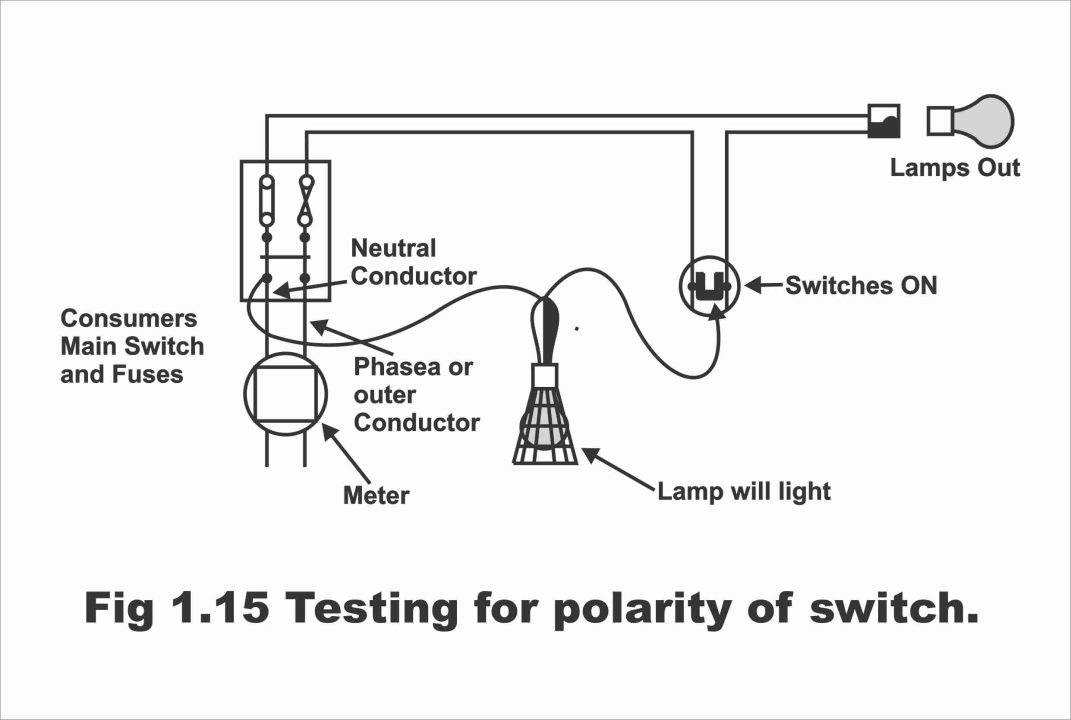
If electric supply (electricity) is available, in this case, a polarity test is conducted through a test lamp. In this type of test, all loads (e.g., fans and lamps, etc.) are disconnected from the circuit, covers, or lids of all the single pole switches are removed and then turned ON. The main switch is turned ON by fitting the main fuses. Now one end of the test lamp is connected with the neutral terminal of the main switch, whereas its other end is connected turn by turn with any one terminal of every switch, as has been illustrated in figure 1.15. if the test lamp irradiates by doing so, it means that the switch has been fitted on the phase wire. If the lamp doe not illuminates, it means that it is installed on the neutral instead of a phase wire, which is subsequently fitted along the phase wire. As such, the polarity of every switch present on the wiring is tested turn by turn.
Figure 1.15 – Testing for the polarity of a switch
Polarity Test by Megger
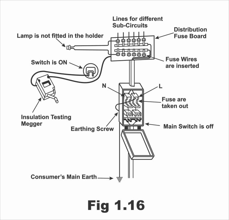
If supply does not exist on the wiring, in such a situation a megger is used to conduct a polarity test. According to this method, fuses are inserted within all fuse links. All loads (electrical appliances and lamps) are isolated from the circuit. Covers or lids of all the switches are removed and they are turned ON. One of the megger’s wires is connected to the phase while the other long wire is connected with any of the terminals of every switch and then the megger is rotated at a uniform pace. If megger’s needle immediately drops down on zero, it signifies that all switches are precisely fitted on the phase wire. And if the megger needle stops on the infinity sign, it means that switches have been installed on the neutral wire. In figure 1.16, this type of test has been demonstrated.
Figure 1.16
Polarity Test by a Continuity Tester
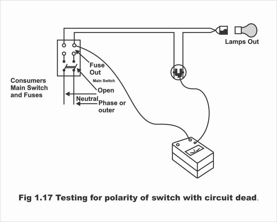
For wiring in the newly constructed buildings, a continuity tester is also used for determining the polarity of switches in the absence of supply. According to this test, the main switch is turned OFF, and fuses, lamps, and other appliances are removed or detached from the circuit. Whereas lids of the single-pole switches are removed and they are turned ON. Thereafter, one of the wires of the continuity tester is connected to the phase on the switch fuse, whereas the other wire is touched with the terminals of all single pole switches by turns. By doing so, if the needle of the continuity tester shows a reading of less than one ohm, then the polarity of the switch is correct i.e., the switch is on the phase wire. (Remember that in such a situation, this instrument keeps on measuring the resistance of the wiring circuit from the main fuse up to the testing switch). This has been illustrated in figure 1.17. On the contrary, if the switch has been installed on a neutral wire, then the continuity tester will indicate an infinity reading. In this case, a switch is fitted along a phase wire. Remember that bulb–maintained continuity testers are also available instead of customary needle-equipped testers, wherein a bulb illuminates in case of a right polarity, which implies that the switch has been fitted on the phase wire. The switch on which the continuity tester’s bulb does not irradiate signifies that the switch is on a neutral wire, which can easily be fitted along a phase wire.
Figure 1.17 – testing for the polarity of a switch with circuit dead
Continuity testing of electrical installations
After completion of the wiring, a continuity test is conducted to ascertain electricity continuity between different lengths of wires and cables. Its objective is to determine whether any wire has been broken somewhere or not. Actually, keeping a continuity of phase wire and neutral wire up to the load is necessary. It is also essential that connections of all fuses and single pole switches on the phase wire should be correct, otherwise electric appliances (e.g., bulb, fan, etc.) fitted along the corresponding load won’t operate. A continuity test is carried out for the corroboration of these particular assignments. This test can also be performed through a megger as well as a continuity tester.
The following steps have to be taken for ascertaining the wire’s continuity with the help of a megger;
(i). All appliances are disconnected from the wiring, and lamps are removed from all the lamp holders
(ii). All switches are turned ON
(iii). Terminals of holders and sockets are mutually connected
(iv). All fuses are inserted
(v). Both wires are drawn out from the main switch and connected with both the megger terminals
(vi). Megger’s handle is rotated at a uniform speed and its reading is checked. If the meggers needle drops down suddenly to zero, it means that required continuity persists in the wires (i.e., continuity is correct) and if the needle halts on the infinity sign, continuity between different lengths of wires do not exist (i.e., wires have been broken somewhere). In figure 1.18, the continuity wiring test has been illustrated.
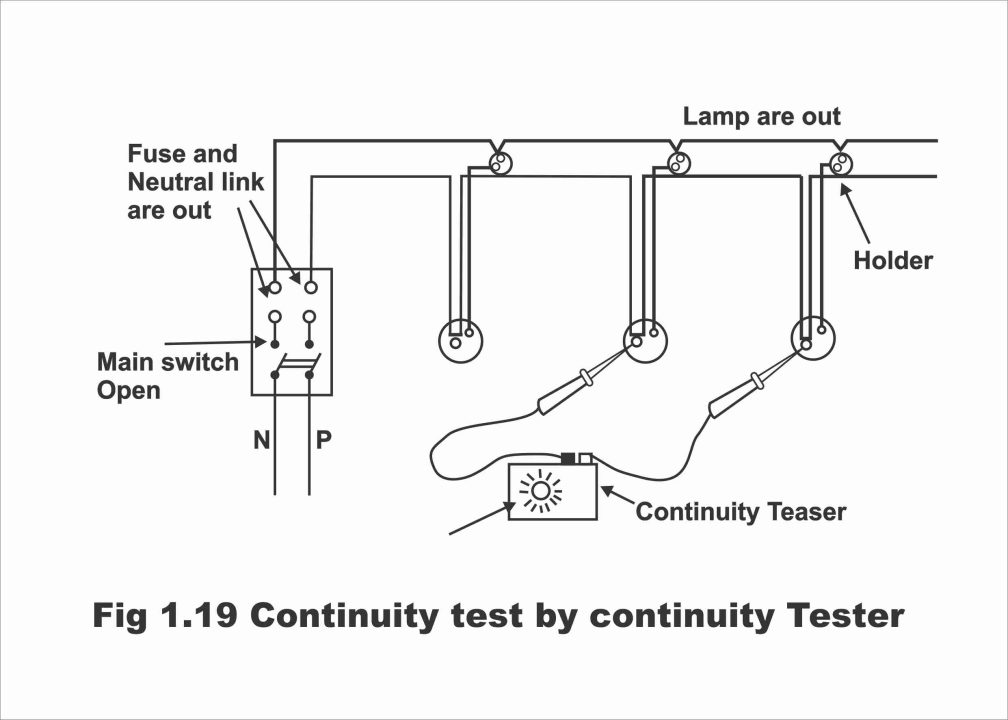
In case this test is conducted through a continuity tester instead of a megger, all bulbs on the circuits are removed and all-electric appliances are detached (e.g., connections of fans, etc. are removed from ceiling rows). Switches lids or covers are removed and turned OFF. Moreover, fuse and neutral links are unplugged. If the tester bulb irradiates by connecting one end or wire of the continuity tester to the one switch terminal and the second wire with the other switch terminal, then continuity is correct (i.e., switches have a single wire series) otherwise, wiring is cut on some places. This process is repeated between every two switches alternately. In figure 1.19, the continuity test has been illustrated. Similarly, continuity of the neutral wire within all holders and sockets is also tested.
Figure 1,18 – Continuity test of wiring
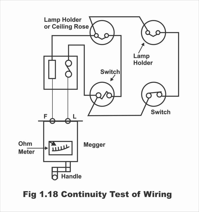
Figure 1.19 – Continuity test by continuity tester
Continuity Test of Earth Connection
In the case of conduit wiring, electric continuity among all the metal conduits and its earthing on one spot is also essential for safety purposes. Otherwise in case of damage to the insulation, leakage current may pass through the conduit, and a person who touches it can be susceptible to an electric shock. There is also a possibility of conduit joints getting loose or resistance of earth path getting high in conduit wiring. It is also observed in this type of test whether earth continuity exists or does not exist between the conduit and the metal appliances going to be applied along with it. In other words, the objective of this test is to ascertain the efficacy and performance of the earthing system. The following method is employed to check this continuity;
A long wire is annexed along with the line terminal of a megger, whereas another end of this wire is peeled off or scratched and fastened with an end of the metal pipe (conduit). Whereas, another wire is annexed to the megger’s earth terminal and its other end is peeled off and connected with the final part of the pipe. After this, megger’s handle is rotated at a uniform speed. If the megger’s needle comes to zero resistance by doing so, it reflects a connection between the pipes i.e., continuity is satisfactory. However, if megger’s needle stands idle on infinity, it reflects that the joint of the pipes is loose somewhere, which is essential to be tightened. By cleaning rust etc. from the joints and tightening the joints, their continuity can be restored.
Insulation Test or Leakage testing of electrical installations
The wiring insulation resistance of a consumer is tested through an insulation resistance test. The objective behind this test is to inspect insulation resistance between the conductor and the earth (or conductor to conductor) and check whether any wires have been scratched and touched the earth. In other words, the objective behind this test is to assess whether the wire insulation used in this system of wiring is correct or not, so that the current leakage could be averted. Because, if the insulation is weak, current tends to leak through the wires and flows towards the wall or ground. Resultantly, electricity cost will increase owing to the running of the meter without any type of load on it. Remember that value of the insulation resistance is so high that it is measured in megaohms. And the higher the insulation resistance of some wiring, the better that wiring is considered.
According to the electricity rules, the value of the leakage current must not exceed 0.02 percent or 1/5000 to the full load current being used in a consumer’s premises. if the value of leakage current exceeds this value, it means that insulation is feeble, which can cause a short circuit between conductor and earth or between conductors at any moment. As such, if the quantity of insulation resistance is so low, that leakage current above the required limits can pass through it, such wiring is treated as being defective. An insulation test is conducted on DC volts, which have a double value as compared to a working voltage, however, not more than 500 volts. For this purpose, a megger is brought into use.
As per IEE rules, wiring insulation in residential premises should be calculated according to the following formula;
Insulation Resistance of VIR Cable (Mega – Ohms) = 50 / No. of outlets
Insulation Resistance of PVC Cable = 12.5/ No. of Outlets or Load points
Outlets mean all those appliances which are normally used in household wiring e.g., lamps, switches, sockets, fans, etc. A lighting point controlled by a single switch consists of two outlets whereas one switch socket will have one outlet. For example, if the number of such appliances in a house is 5 with a VIR type cable wiring, in such a situation, the wiring insulation of this premises must not be less than the following value;
Insulation Resistance = 50 / No. of outlets = 50 / 5 = 10 M-Ω
The insulation test is conducted through the following two methods;
(1). Insulation Test Between Conductor & Earth or Leakage Test
(ii). Conductor to Conductor Test
The objective of this type of test is to check the insulation resistance found between conductors and earth on an entire wiring system along with fittings. Because the presence of appropriate insulation between the current transmitting conductors and earth on any wiring installations is necessary. The higher the insulation resistance between the conductor and earth, the better the wiring system will be considered. If the value of insulation resistance is low, it will result in the leakage of current, which may cause material as well as human loss.
The following steps are taken before the conduction of an insulation resistance test;
- The main switch is turned OFF
- The main fuse is unplugged
iii. All the distribution fuses are plugged, or fuses are removed and a fuse wire is used instead of them
- Anyone load is exerted onto all the circuits and their switches are turned OFF
- Lamps are fitted onto all the lamp holders and their switches are turned ON
- The neutral and phase wires are scratched and joined or shorted on the main switch and these wires are then connected to the “L” terminal of the megger.
For conducting this type of test, the L terminal of the megger is connected with one end of the wire while its other end is connected to the interconnected phase and neutral wires on the main switch. Whereas one of the wires is connected to the E terminal of the megger and then linked with the earthing screw of the earthed main switch or a water tap. Then megger is rotated swiftly at a uniform speed (megger should be rotated at such a pace that its handle tends to slip). Then megger’s reading is noted down, which represents insulation resistance observed between the wiring and the earth.
According to the IEE regulations, this measured resistance value should not be less than the value obtained by dividing 50 megaohms by the number of outlets (i.e., 50Ω/ number of outlets). Actually, in this type of test, the resistance measured from the megger is compared with the resistance obtained through the aforementioned formula. If the resistance gained through the test is higher than the resistance attained through the formula, the wiring insulation is considered to be satisfactory. On the contrary, if the resistance received through the formula is higher than the resistance attained through the test, then the wiring resistance is treated as defective. It should be remembered that the resistance of the household wiring must not be less than one megaohm. However, if the number of outlets is large, then insulation resistance must in no way be less than 0.5 megaohms.
For example, if the number of outlets (e.g., fans, lamps, irons, etc. which are on the circuit during the test) in a home is 10 and wiring has been carried out through a VIR cable, then cables’ insulation resistance as a result of this test must not be less than 50/10 = 5 megaohm. If meggerdenotes a reading higher than this value, then wiring can be acceptable and if it reveals a value less than this, then the wiring is defective. In this situation, every part of the wiring is tested separately to search for the faulty part.
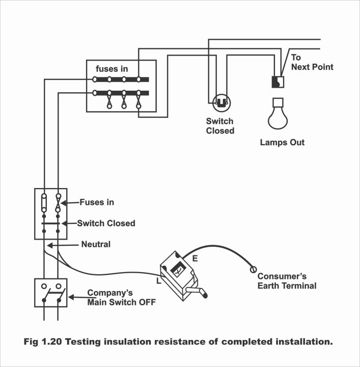
In figure 1.20, an insulation resistance test has been illustrated between the earth and all conductors after the wiring has been completed.
Figure 1.20 – Testing insulation resistance of completed installation
Insulation Test Between Conductor & Conductor or Short Circuit Test
The objective of this test is to check the insulation resistance between the conductors of any wiring system without fittings. That’s it is seen in this test whether satisfactory insulation exists between a phase conductor and a neutral conductor or not. Because if appropriate insulation does not exist between them, a short circuit can happen, due to which wiring may be damaged. In other words, the purpose of this test is to ensure that without fittings insulation resistance between the conductors is sound, so that leakage does not occur between them.
The following steps are being taken before the conduction of this test;
i). The loop existing on the main switch is ceased (i.e., the interconnected phase and neutral wires on the main switch are separated)
ii). All the lamps fitted on the holders are put down and the rest of the loads (e.g., fans, irons, etc.) are also removed from the wiring.
iii). All the fuses on the distribution fuse boards are plugged
iv). The main switch is turned OFF
v). The main fuses are unplugged
vi). All the switches are turned ON
For carrying out this type of test, the phase wire from the main switch is connected to the L terminal of the megger, whereas the neutral wire is connected to the E terminal of the megger. This has been illustrated in figure 1.21. After this, the megger is circulated very rapidly at a uniform speed and the reading of insulation resistance is obtained from the megger’s scale in ohms. The value of such a reading must not be less than the reading obtained through the following formula;
Insulation Resistance (VIR Cable) = 50MΩ/ No. of outlets
Insulation Resistance (PVC Cable) = 12.5MΩ/ No. of outlets
It should be remembered that the value of the insulation resistance obtained through the test must in no way be less than 0.5 ohms. If the megger’s needle reaches 0 during the test, it means that a short circuit exists between both the wires, which should be rectified before the provision of the supply.
Figure 1.21 – Testing between the conductors of a 2-wire insulation
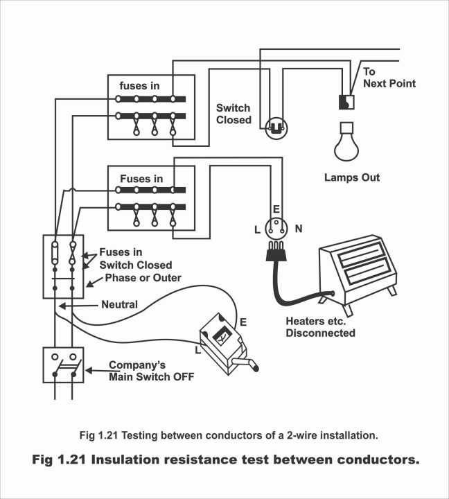
Figure 1.21 – Insulation resistance test between the conductors
Short Circuit testing of electrical installations
As a result of wrong connections in the wiring, a short circuit occurs as soon as the supply is turned ON due to the phase and neutral wires having been interconnected. As a result, the wiring will get heated due to an excessive flow of current through the wires and consequently, their insulation will melt. Moreover, the entire wiring system can be vulnerable to fire as a result of a short circuit. The purpose of conducting a short circuit test is to determine or check, whether phase and neutral wires touch each other at some places on the wiring or whether both these wires connect each other at certain places as a result of the insulation’s abrasion. In other words, the objective behind a short circuit test is to check or find out a possible short circuit in the wiring.
This type of test is carried out in the following ways after the completion of the wiring;
1). All the lamps plugged into the lamp holders are removed
2). Fans’ connections are removed from all the ceiling rows
3). All the loads (e.g., TV, water cooler, air conditioner, refrigerator, etc.) are detached from the circuit or unplugged
4). All the fuses on the circuits are left as it is
5). All the switches, main switches, and fans’ regulators are turned ON
6). Both the wires ejecting from the mainboard are connected to the line and earth terminals of the megger. That’s phase wire is connected to the megger’s L terminal while the neutral wire is connected to the E terminal of the megger. This has been illustrated in figure 1.22.
7). Now, megger’s handle is revolved swiftly at an unvarying speed. By doing so, if the megger’s needle stops at infinity, or shows a very low reading, no short circuit exists on the wires and their insulation resistance is sound.
8). If the megger’s needle shifts to zero as soon as the megger’s handle is circulated, it indicates that a short circuit exists in the wiring. It is necessary to search and eliminate it before the provision of supply. To ascertain where the short circuit exists, all the switches are being turned OFF by turns while rotating the megger’s handle. The switch, on which the needle returns to the infinity upon it turning OFF, that circuit has a short circuit.
Figure 1.22 – The short circuit test

Earth Resistance testing of electrical installations
By earth resistance, we actually mean the resistance existing between the earth electrodes and the earth. Earth consists of a zero resistance as a result of its large cross-section (i.e., earth’s resistance is supposed to be zero). As a result of a zero-earth resistance, the earth’s potential is also considered zero, which is being taken as a reference. Actually, resistance existing between the earth’s surface to the earth’s electrode consists of the following;
i). Electrode’s own resistance
ii). Connect resistance between the electrode and earth
iii). Resistance of the soil between two electrodes, where measurement is desired to be carried out
However, the electrodes’ resistance is almost equal to nothing or it is quite negligible. Similarly, the resistance of the soil existing between the two electrodes is also negligible. In fact, earth resistance consists of the connect resistance found between the electrode and earth.
It is very important to know the value of resistance existing between the earthing plate or earth electrode and its surrounding ground. This test is normally conducted through an earth resistance tester, which is an amended form of a megger (i.e., this instrument is made by making a small modification in the megger). The low resistance existing between electrical installations and the earth is measured by an earth tester. However, this test can also be conducted with a voltmeter and an ampere meter by supplying current on a power frequency through a double wound transformer. It ought to be remembered that the measurement of the earth’s resistance in an earth resistance test is done by the potential fall method.
We know that the resistance area of an earth’s electrode is actually the soil area around an electrode, on which quantity of voltage gradient (i.e., fluctuations in voltage) is measured through measurement instruments (e.g., voltmeter, ammeter, etc.). In figure 1.23, the earth resistance test of an earth electrode has been illustrated. In this figure, X is the earth electrode, which is going to be tested, whereas Y is an auxiliary earth electrode, the objective behind the installation of which is to protect two resistance areas from overlapping. Z is another auxiliary electrode, which is installed right in the middle of the X and Y electrodes.
Now a constant value alternating current is transmitted through the earth from X towards Y, which is measured by an ammeter. Let us suppose that both X and Y electrodes are similar. In such a situation, the voltage drop as a result of resistance on X and areas surrounding it, should be half of the overall voltage drop. The other half of the total voltage drop will occur on Y and the areas surrounding it. The resistance between X and Y resistance areas will almost be negligible, therefore voltage drop will also be equal to nothing. The voltage drop occurring between X and Z is measured through a voltmeter. Thus, the resistance of the X electrode will be as follows;
The resistance of X = Voltage-drop between X and Z / Current between X and Y = V / I … (ohms)
To protect the resistance areas from overlapping, auxiliary electrode Z is moved to positions Z1 and Z2 respectively. However, the resistance value in all these three situations almost tends to be equal.
Figure 1.23 – Test of the earth – electrode resistance (I.E.E)

Next Topic: Introduction and Types of Service Line
Previous Topic: Types of Earthing Systems
For electronics and programming-related projects visit my YouTube channel.
Discover more from Electronic Clinic
Subscribe to get the latest posts sent to your email.


I learned alot from your teaching and explanations about Electrical tasks