Earthing System for home: Plate and Pipe Earthing
Last Updated on August 20, 2023 by Engr. Shahzada Fahad
Table of Contents
Types of Earthing System for home
Earthing is generally done according to the undermentioned two methods;
- Plate Earthing System for home
- Pipe or Copper Rod Earthing System for home
Figure 1.11 – earthing of a single motor from two places
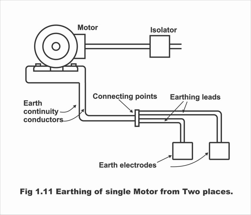
Plate Earthing
If a copper or an iron plate is used as an earth electrode, then this system of earthing is called plate earthing. In Pakistan, both copper, as well as iron-type earthing plates, are used. Copperplate tends to be 2 feet long, 2 feet wide and 1/8 inches thick (600 x 600 x 3 millimeters) whereas the size of the iron plate is 2 feet x 2 feet x 1/4” millimeter). As the basic objective of an earthing electrode or plate is to coordinate befittingly with the earth all the time, therefore it is far better to bury earthing plate below the water level. However, if it is not possible, then the plate is dug into some misty place and water is poured onto it occasionally from outside. A plate is being dug into the earth in a vertical condition and a solid layer of one foot (approx. 300 mm) minimum made from a mixture of charcoal and lime, is built around it. The depth where the plate is going to be buried depends on local conditions. First of all, the soil of the place, where earthing is desired to be done, is tested. As the resistance of a greasy type of soil is low, therefore it is preferred over a piece of earth covered with sand or stones.
After testing the soil, a den about 20 to 25 feet deep or one foot below the water surface, having a minimum size of 5 feet x 5 feet are dug. (Remember that the water level of different places tends to be diverse, therefore plates deepness also differs at various places. However, the plate’s depth must in no way be less than 3 meters (10 feet) and it must be at least one foot lower than the constant water level). After digging the den, an iron or copper earth plate is buried straight into it. By making a hole in the center of the earth plate, 8 SWG wire is stiffened around the plate through nuts and bolts. This wire, which has been annexed with an earth plate, is then transmitted into a conduit pipe (so that wire does not get rusty owing to moisture and soil) and jointed or screwed with the body of the machine which is subjected to be earthed.
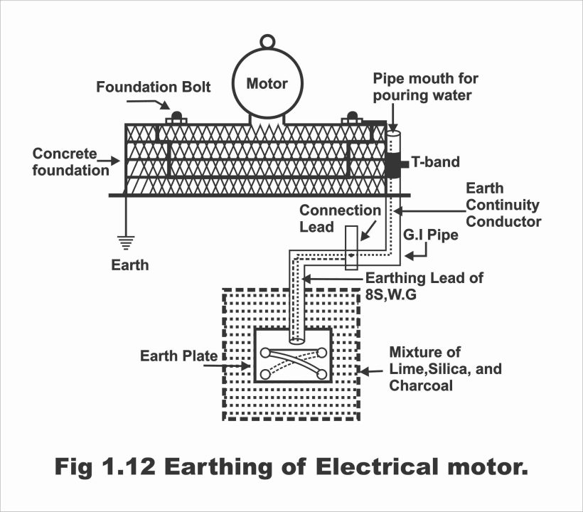
Then a minimum of one feet mixture of charcoal and lime is filled around the straightly fixed earth plate in the den, so that moisture remains intact around the plate. As a result of this operation, plate size as well as its continuity with the earth also increases. Further, this earth’s resistance also does not increase. Two buckets of water are also dropped between the mixture of lime and charcoal. Finally, this hole is filled up with soil and a T- band is fitted on the conduit pipe (within which earth wire is passed and brought up to the motor frame), through which water is poured after one or two months so that the earth does not get dry. Remember that the mouth of the T-Band must be at least 2 inches high from the ground surface and the earth plate must be planted into the ground at least 5 feet away from the house foundation. The most suitable place for burying an earth plate is one, where rainwater drips from the roof through a water spout during the rainy season so that whenever it rains, all roof water reaches up to the earth plate. In figure 1.12, the procedure of burying an earth plate in the ground has been illustrated. If the machine is desired to double earthed, the procedure for burying the second earth plate is also the same.
Figure – the earthing of an electric motor
Pipe or Copper Rod Earthing System for Home:
If a copper rod or an iron pipe is used instead of an earth plate for earthing, this method of earthing is called pipe or copper rod earthing.
During small installations, an iron pipe is used for earthing instead of an earth plate, the diameter of which must not be less than 25 mm (1 inch) and a length of 2 meters (6 feet). This pipe must be at least 2 feet deep from the ground surface. The pipe is fitted straight or in a vertical manner inside the den. In order to preserve moisture, a 25 mm (1 inch) mixture of charcoal and lime is filled around the pipe. Further, water is also poured from above through the pipe. Most often, substitute layers of salt and coal are built around the pipe in the den for achieving better results. For instance, if the first layer is of salt, the second layer will be that of coal. Then the third layer will be of salt and the fourth layer will once again be of coal. For earthing the house wiring, factory wiring (particularly electrical installations in large factories), and neutral wiring of the supply line, normally a galvanized iron (G.I) pipe is used instead of an earth electrode, the exact size of which actually depends on fault current and soil conditions.
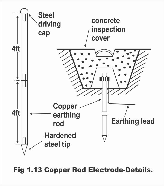
For effectiveness and facility purposes, where ever the water level is shallow, brass rods are used there as earth electrodes for earthing, the diameter of which can be from 12.5 mm (1/2 inches) to 25 mm (1 inch) and length approx. 4 meters (12 feet). Normally, every rod is made of 4 feet length and for getting the desired length, 2 or 3 rods are firmly tightened through screw coupling. The lower end of the rod consists of a tough steel tip (so that it can easily find its way through the earth) whereas, on its top end, a tough steel cap is being formed for striking with a hammer. This has been illustrated in figure 1.13. However, the rest of the rod is made from iron.
In order to use copper rods as earth electrodes, no extensive digging is required. Rather, the cap built on top of the rod is stroked repeatedly through a hammer to bury it through the ground, up to the desired depth. After burying the rod to the desired depth in the ground, its top end is covered in strong concrete made den, so that the risk of breaking the earthing lead could be eliminated. The greatest advantage of this type of rod is that lengths of earth electrodes can be increased or decreased according to one’s needs through standard lengths and there is no need for any sort of digging as well in this method. Moreover, it is also time-saving and does not involve too much labor. It is worth remembering that the length of the rod is more important in this method compared to its diameter because access to the desired depth in the earth can be achieved by using a long rod, where soil’s specific resistance is constantly low. In this way, the best possible connection is established through the earth. This method is mostly used in foreign countries.
Figure 1.13 – Copper rod electrode details
Protective Multiple Earthing or P.M.E
A method of earthing, in which the earth continuity conductor is not only connected to a consumer’s premises but also connected with a neutral conductor of the power supply, is called protective multiple earthing (P.M.E). The greatest advantage of this method is that in case the neutral wire is broken, the earth fault current flows back towards the supply source through a neutral existing parallel to the earth. And as such a low resistance path is developed, which melts down the fuse or enables a protective device (because an excessive current passes through the fuse owing to low resistance, as a result of which it melts down). As a result, the risk of an electric shock due to the breaking of a neutral wire tends to eliminate (i.e., in the case of earthing from two points or places, electric shock does not occur even if a neutral wire has been broken). Remember that if this is not done, the current does not flow back towards the supply source in case the neutral wire has been broken and an electric shock will be felt upon touching the neutral wire.
As in protective multiple earthing systems, the neutral wire of the power supply is also connected to the consumer’s earthing system (or included in the consumer’s earthing system), therefore in the situation of a neutral wire breaking down, current flows back under the earthing system. Thus, even if a neutral wire is broken, no electric shock occurs even if it is touched. Foreign supply companies often use multiple protective earthing systems in rural areas of foreign countries, where earthing conditions are not so feasible (i.e., in mountainous or hilly areas, etc.) and where huge expenses have to be incurred on every premises for achieving low resistance. It should be remembered here that PME is used in those areas as per written permission of the concerned supply company, where acquisition of low earth loop resistance is difficult from the supply transformer to the consumer’s terminal.
Although this system is very effective from the viewpoint of providing a better earthing system, however, some new issues have to be confronted as a result of this system which may cause considerable loss. For example, it is immensely important that the potential of a neutral conductor should not exceed a dangerous level with respect to the earthing, because all protective metalwork (i.e., metal sheaths of such machines and appliances, which have been protected through earthing) are connected with a neutral of the supply. As such, the risk of any electric shock within a specific distribution network enhances. Particularly, chances of such an incidence increase in the event of breaking down of a neutral conductor. Such a situation frequently occurs in rural overhead lines. The dangerous scenario resulting from such a situation has been depicted vide figure 1.14.
Figure 1.14 – Protective multiple earthing
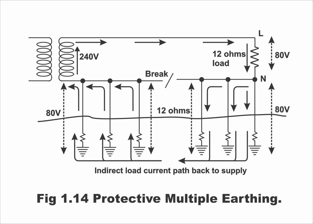
Suppose that load of a consumer in a PME-based distribution system is 5KW (supply is provided on this load at 240 volts and load resistance is about 12 ohms). If the supply’s neutral conductor breaks down somewhere on the path for any reason, in such a situation there is no way for the normal load current to return up to the supply, however, this load current finds an alternate indirect path for flowing back up to the supply terminals through some other earthed neutrals existing on the distribution system, as has been illustrated in the figure. As such, current flows down from these connections towards the earth in a parallel path and reaches back towards the supply terminal via electrodes existing on another side of the break. If the resistance of every electrode is also approx. 12 ohm, it means that 240 volts supply voltage is now equally distributed on both sides of load and break in parallel (i.e., 80V on load, whereas 80V of the remaining 160V on one side of the break and 80V on another side of the break are distributed). As a result, every earthed metalwork existing on each installation supplied through the distribution system now energizes on approx. 80V (i.e., 80V are found between every earthed sheath and the earth). In such a situation, if a person touches any earthed metal sheath or metalwork, he receives an electric shock of 80V, which is one of the greatest drawbacks of this type of earthing system.
A similar effect occurs even in case a high resistance is fitted on neutral. However, the danger of shock and damage depends on the resistance of the load and the neutral return system. The disadvantage of this type of earthing system is that the flow of current towards the load continues uninterruptedly and one remains clueless about any sort of defect or fault if any person touches metalwork, he receives an electric shock.
As a result of these dangers, the conditions or requirements of PME are very strict and for undertaking this type of earthing in any specific area, seeking formal approval from the concerned ministry is mandatory. The basic requirements include the earthing of the neutral conductor at several points of the system and that between every conductor and earth maximum resistance must not exceed 5 ohms. Moreover, an earth electrode is also recommended for the installation of every consumer. This type of earthing system is very rarely used in Pakistan except in some hilly regions. Because, in mountainous areas, satisfactory spots for earthing purposes are not generally available.
Next Topic: Methods of Testing Electrical Installations
Previous Topic: Introduction and components of Earthing System
For electronics and programming-related projects visit my YouTube channel.
Discover more from Electronic Clinic
Subscribe to get the latest posts sent to your email.