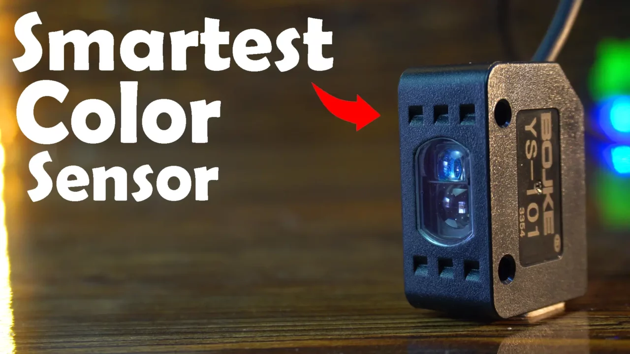
Smart Color Mark Photoelectric Sensor with ESP32
Last Updated on March 1, 2025 by Engr. Shahzada Fahad
Table of Contents
Smart Color Mark Photoelectric Sensor:
Smart Color Mark Photoelectric Sensor with ESP32- You all must have seen and used many color sensors before, but the DFRobot’s Smart Color Mark Photoelectric Sensor is going to blow your mind! You can use this sensor with 5V-compatible controller boards like Arduino, and you can also safely use it with 3.3V-compatible controller boards like ESP32, ESP8266, Raspberry Pi Pico, STM32, etc. And since it supports a wide input voltage range, you can even use this Smart Color Sensor with PLCs.
And the best part? Even kids can use this sensor! You don’t need to do any complex programming. Using this Smart Color Mark Photoelectric Sensor is as simple as using a push button. All we need to do is read the High/Low signal from the sensor, and based on that signal, we can perform various actions; control a servo, count objects, turn ON or OFF a specific load, and much more. The possibilities with this color sensor are endless!

This may be a small sensor, but it comes packed with amazing features, which you can access using the buttons provided on the sensor. How to use these buttons and their functions can be found on the sensor’s official page.
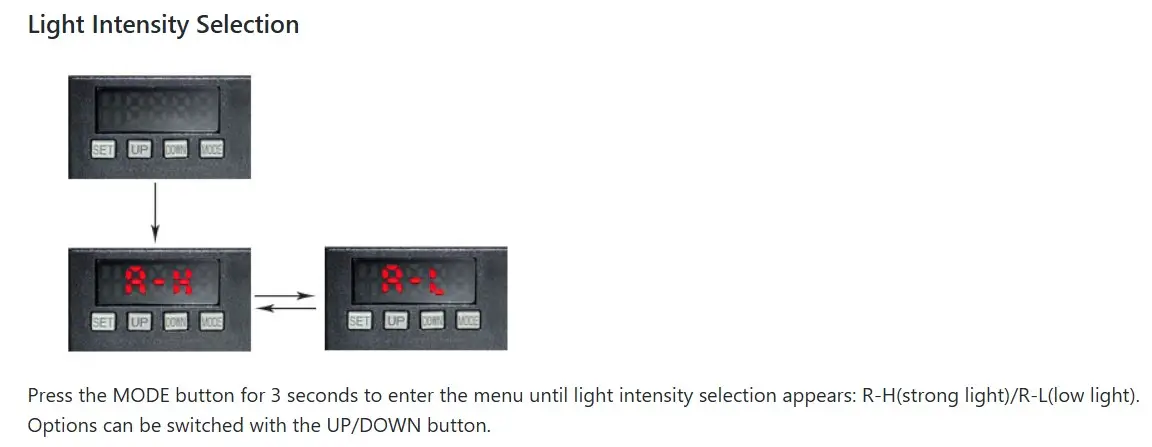
By entering the menu, you can adjust the “Light Intensity Selection”, allowing you to choose between Strong light and Low light.
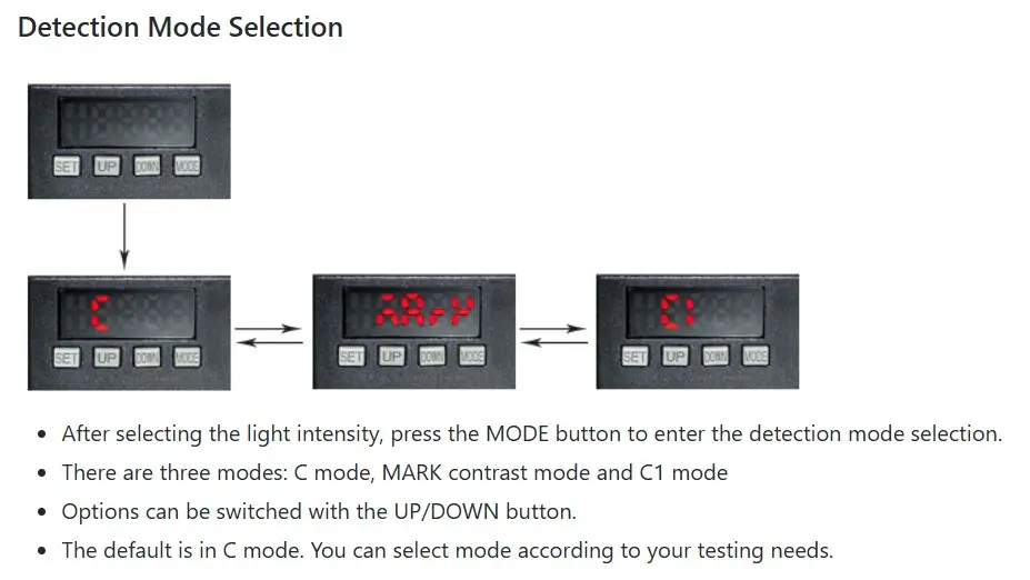
You can also select the mode- there are three modes:
- C Mode
- MARK Contrast Mode
- C1 Mode
You can choose any of these three modes based on your testing requirements.
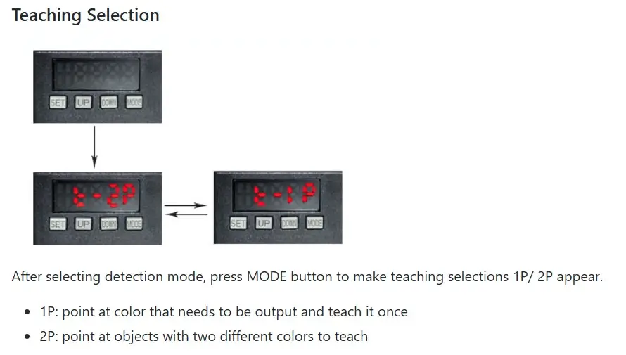
You can also switch between 1P and 2P under Teaching Selection.
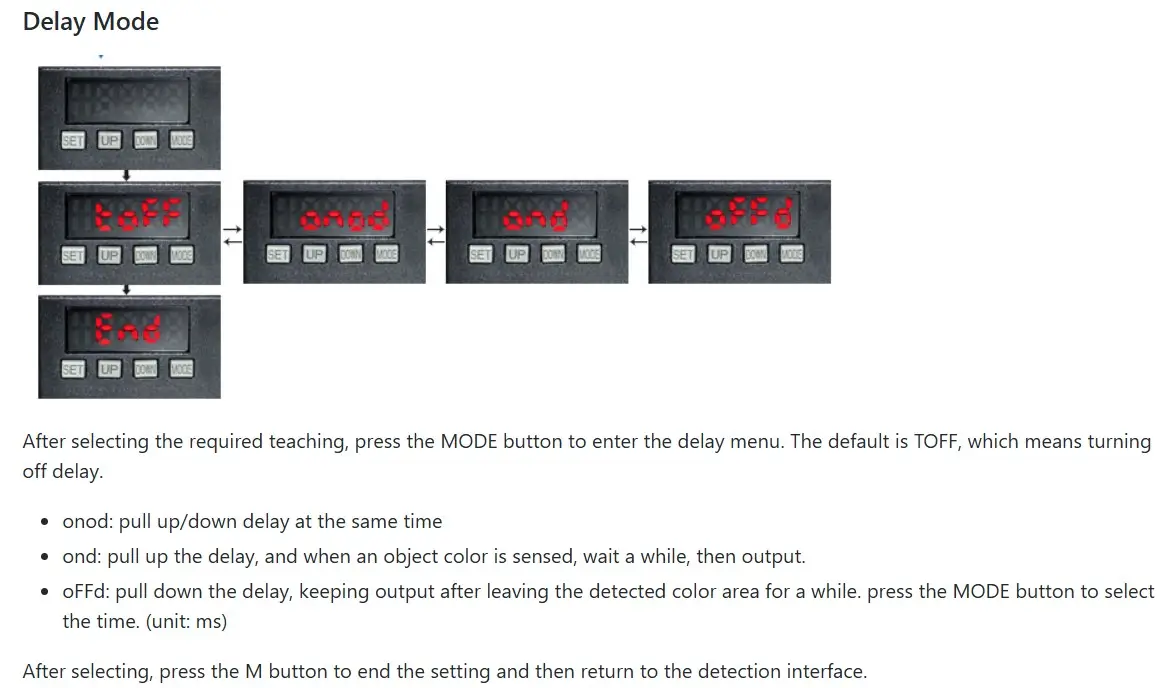
Additionally, you can select any “Delay Mode” of your choice.
Feel free to explore the menu, change different options, and test various modes. And if at any point you make a mistake or feel like you messed up the settings, simply press and hold the SET and MODE buttons for three seconds to restore the factory settings.
Amazon Links:
ESP32 WiFi + Bluetooth Module (Recommended)
Smart Color Mark Photoelectric Sensor
Other Tools and Components:
Arduino Nano USB C type (Recommended)
*Please Note: These are affiliate links. I may make a commission if you buy the components through these links. I would appreciate your support in this way!
Specifications of Smart Color Mark Photoelectric Sensor:
| Light Source | Four-element LED |
| Sensing Distance | 8~16mm |
| Power Supply | DC12-24V |
| Response Time | Mode of MARK: 50µm;
Mode of C/C1: 130µm |
| Output Selection | LIGHT-ON/DARK-ON (switching select) |
| Detection Method | Detection of light intensity MARK
Detection of automatic color matching C Detection of color and brightness C1 |
| Delay Function | Turn off delay timer/turn-on delay timer/one-shot
timer/turn-on delay one-shot timer, optionally. Selectable timer time: 1ms to 9999ms |
| Ambient Luminance | Incandescent Lamp: max 20000 Lux
Sunlight: max 30000 Lux |
| Power Consumption | Standard mode: max 300mW @ 24V |
| Operating Temperature | -10~55°C |
| Output Type | NPN |
- This sensor is designed for high-precision optical detection using a four-element LED light source.
- With a sensing distance of 8 to 16mm, it operates efficiently with a DC 12-24V power supply.
- The response time varies depending on the mode—50µm in MARK mode for detecting light intensity and 130µm in C/C1 modes for automatic color matching and brightness detection.
- The sensor supports configurable output selection, allowing users to switch between LIGHT-ON and DARK-ON modes.
- Additionally, it includes a flexible delay function with a selectable timer range from 1ms to 9999ms, making it suitable for applications requiring precise timing.
- The sensor can handle high ambient luminance levels, up to 30,000 Lux under sunlight.
- It consumes a maximum of 300mW at 24V and operates within a temperature range of -10°C to 55°C.
- With an NPN output type, it integrates easily into various automation and control systems.
The color mark sensor offers 3 detection modes, and 4 output modes. It saves color data with one click, which is pretty easy to use. The sensor provides stable detection of a variety of colors and its 4-digit LED screen displays the real-time output color data.
Besides, the color photoelectric sensor has protection mechanisms like short-circuit protection, overload protection and polarity protection.
Application Case:
- Detection of packing machine with color Mark
- Detection of adhesive tape on metallic copper foil
- Detection of color printing mark on packing bag
- Discrimination of two sides of the encapsulated chip
- Detection of the presence of sealant on metal parts
- Detection of label color on the sprinkler
- Detection of sorting label color on the assembly line
- Detection of the color on the cup and so on…
Sensor Wires:
| Name | Function |
| Brown wire | Sensor+ |
| Blue wire | Sensor- |
| Black wire | Sensor signal output wire |
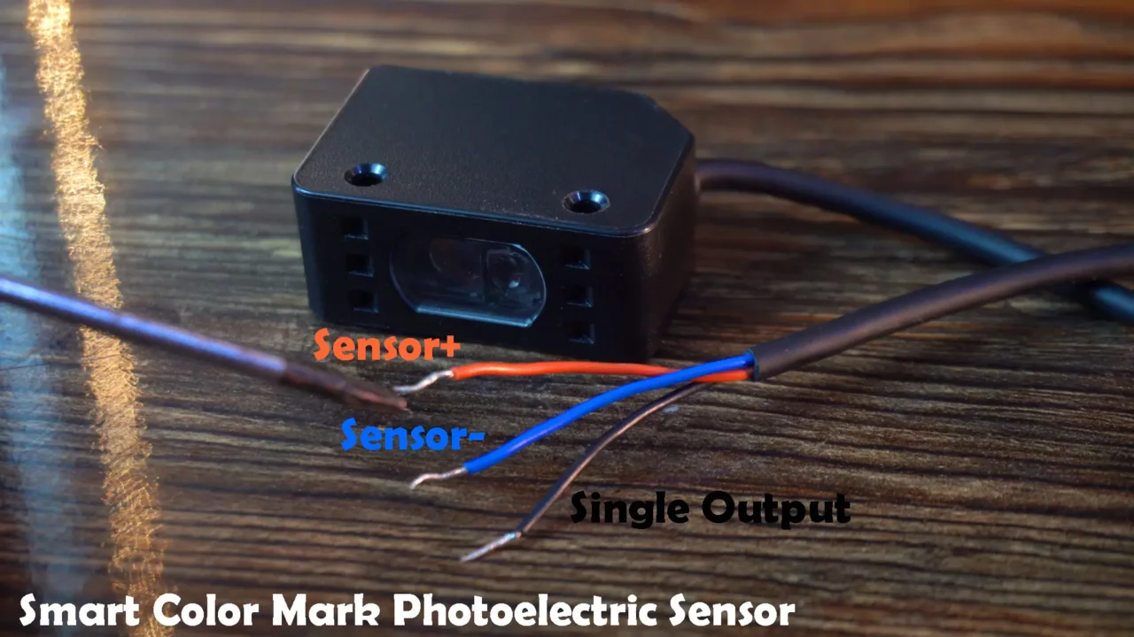
The sensor has a total of three wires.
The Brown and Blue wires, which are the Sensor+ and Sensor-, should be connected accordingly. Connect the Brown wire to a voltage source from 12V to 24V, and connect the Blue wire to the ground.
The Black wire is the Sensor signal output wire and you can connect it to any GPIO pin.
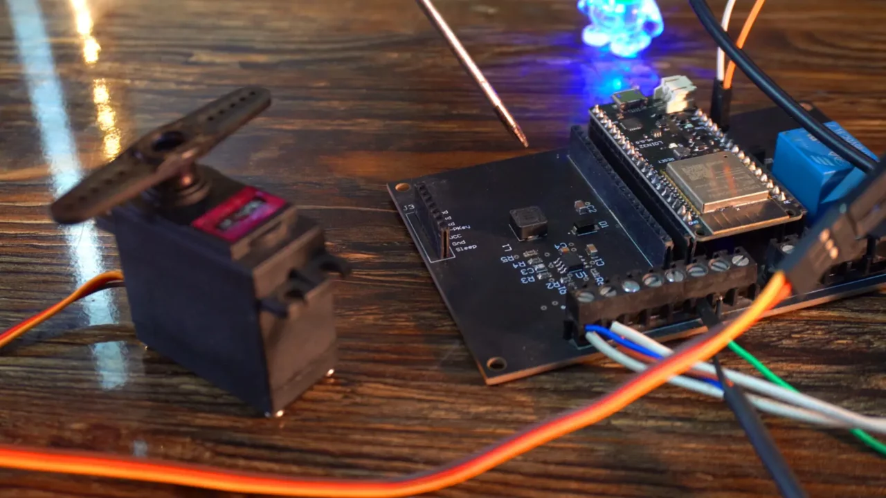
Color Sensor Interfacing with ESP32:
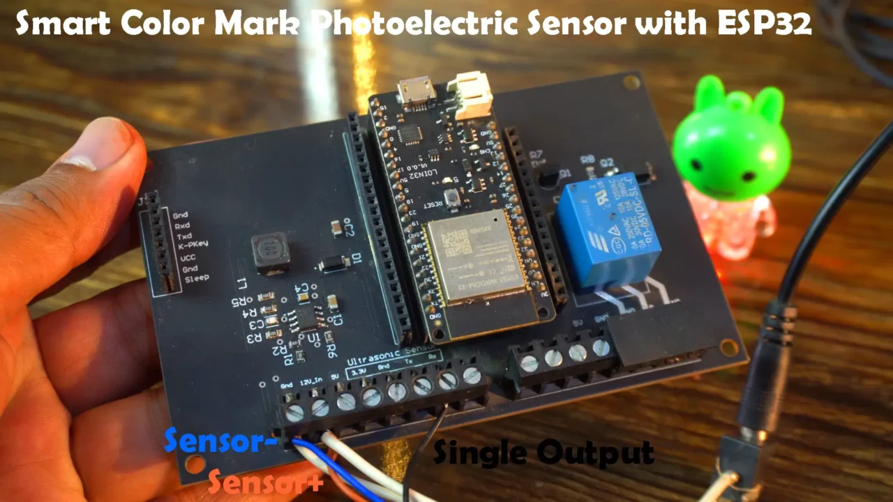
I have connected the sensor’s brown wire to 12V, the blue wire to Ground, and the signal output wire to GPIO16 on the ESP32.
I have already written quite a detailed article on this development board. So, if you want to build a similar development board, you can read this article.
Example 1:
Now, let’s start with a simple example. We will control the ESP32 onboard LED. When the color sensor detects a white color, the LED will turn ON, and when we remove the white color, the LED will turn OFF.
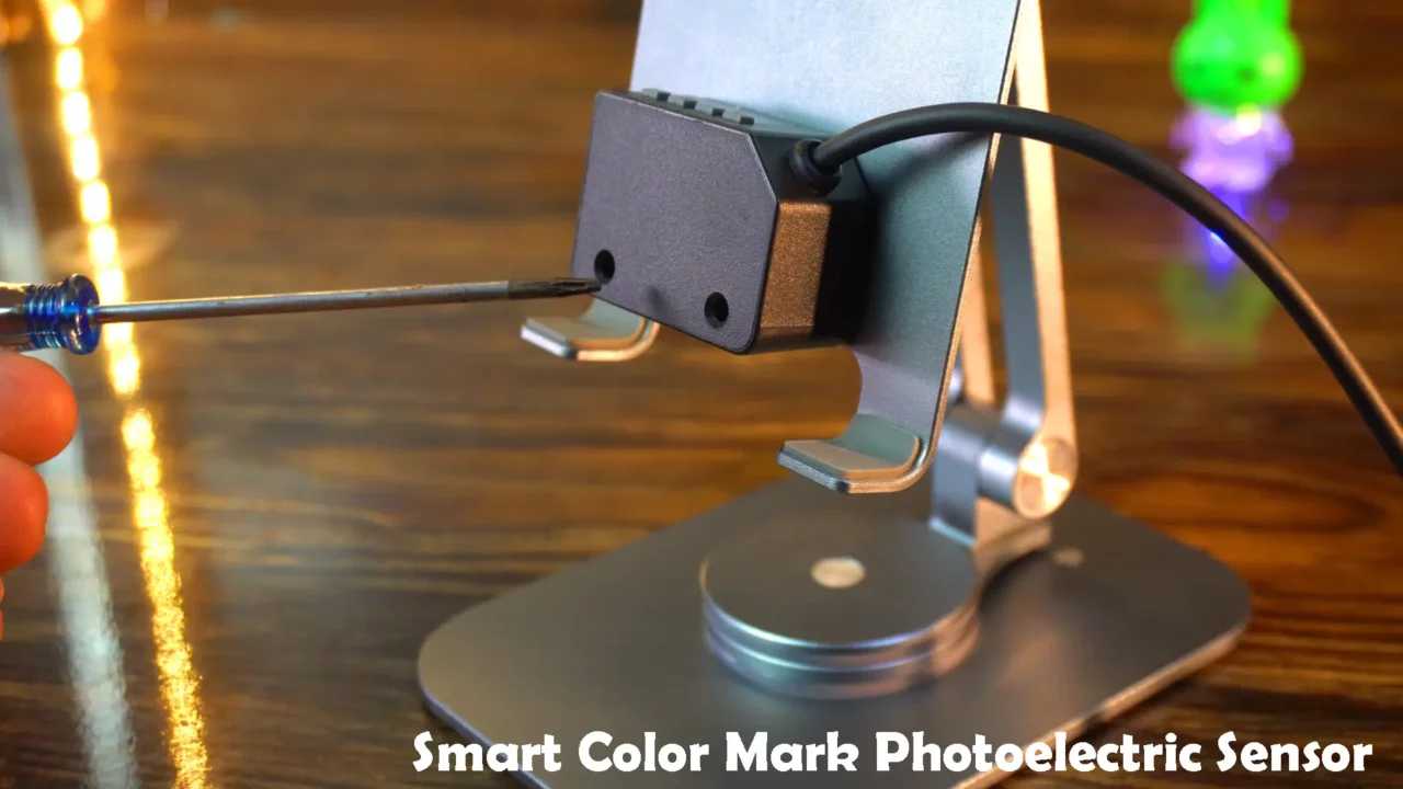
For demonstration, I have mounted the color sensor on this mobile stand. The sensor’s sensing distance should be within 8 to 16mm.
To detect white color, we first need to set it, which is very simple. Follow these steps
- Place the white-colored object under the sensor.
- Press the SET button.
- Remove the object. and
- Press the SET button again.
That’s it! You can use this same technique to set any color.
Next, slightly press the Mode button, and then use the UP and DOWN buttons to increase or decrease the value.
Press the Mode button again to select whether the output signal should be 0 or 1.
If you find it difficult then you can watch the video tutorial given at the end of this article. In that video, I have practically explained how to set any color.
These settings are enough for me. If you want to use the delay mode, you can go to the menu and activate any specific delay mode. Just go ahead and give it a try, as I mentioned earlier; if anything goes wrong, you can reset the Sensor.
Example1 Programming: Controlling an LED:
This code reads a sensor signal on GPIO 16 and controls an LED on GPIO 5. If the sensor output is LOW, the LED turns on; otherwise, it turns off. The loop continuously checks the sensor state and updates the LED accordingly.
|
1 2 3 4 5 6 7 8 9 10 11 12 13 14 15 16 17 18 19 20 |
/* DFRobot's Smart Color Mark Photoelectric Sensor with ESP32 Website: https://www.electroniclinic.com/ */ #define SENSOR_PIN 16 // GPIO where sensor signal is connected #define LED_PIN 5 // GPIO where LED is connected void setup() { pinMode(SENSOR_PIN, INPUT_PULLUP); // Corrected: Use INPUT_PULLUP instead of PULLUP_INPUT pinMode(LED_PIN, OUTPUT); // Set LED pin as output } void loop() { if (digitalRead(SENSOR_PIN) == LOW) { digitalWrite(LED_PIN, HIGH); // Turn on LED } else { digitalWrite(LED_PIN, LOW); // Turn off LED } } |
Practical Demonstration:

At first I couldn’t believe that using a Color Sensor could be that easy. You can set any color in seconds.
Now, let’s make this project a bit more advanced. This time, along with controlling the LED, we will also implement counting.
Let’s imagine that this Smart Color Mark Photoelectric sensor is mounted on a conveyor belt, and white cards are passing in front of it. We need to count these white cards. White color is not compulsory; you can set any color you want. In the next example, we will also try using the blue color.
Anyway, let’s go ahead and take a look at the programming.
Example2: Counter objects:
This time, I have slightly modified the previous code. Now, we are not only turning the LED ON/OFF but also counting the detections. You can use this program for counting almost any type of object.
|
1 2 3 4 5 6 7 8 9 10 11 12 13 14 15 16 17 18 19 20 21 22 23 24 25 26 27 28 29 30 31 32 33 34 35 36 |
/* DFRobot's Smart Color Mark Photoelectric Sensor with ESP32 Website: https://www.electroniclinic.com/ */ #define SENSOR_PIN 16 // GPIO where sensor signal is connected #define LED_PIN 5 // GPIO where LED is connected int lastState = HIGH; // Stores the previous state of the sensor unsigned long counter = 0; // Detection counter void setup() { pinMode(SENSOR_PIN, INPUT_PULLUP); // Use internal pull-up resistor pinMode(LED_PIN, OUTPUT); // Set LED pin as output Serial.begin(115200); // Initialize serial monitor } void loop() { int currentState = digitalRead(SENSOR_PIN); // Read the current state of the sensor // Check if the signal has transitioned from HIGH to LOW (detection event) if (lastState == HIGH && currentState == LOW) { counter++; // Increment the counter only when detecting a signal Serial.print("Detection Count: "); Serial.println(counter); } lastState = currentState; // Update last state for next loop iteration // LED control based on sensor state if (currentState == LOW) { digitalWrite(LED_PIN, HIGH); // Turn on LED when detecting } else { digitalWrite(LED_PIN, LOW); // Turn off LED when not detecting } } |
Practical Demonstration:
image here
I passed the white card in front of the Smart Color Mark Photoelectric Sensor and it successfully not only detected the white card but also incremented the value. I did it more than 49 times. You can see in the video how fast it can do the detection and counting for you. I am totally impressed with this Color Sensor.
Example 3: Servo Control
Servo Wiring:
In the third example, we are going to control this high-torque servo. You need to connect the servo’s red/Orange wire and brown wire to 5V and GND. Then, connect the yellow wire to GPIO17 on the ESP32.
When using a high-torque servo, you must pay attention to the power supply because these servos require more current. On this development board, I have a 5V, 3A power supply, so I can run this servo without any issues. In your case, you can use an external 5V, 3A power supply.
Now, let’s go ahead and take a look at the programming.
Color Sensor and Servo Code:
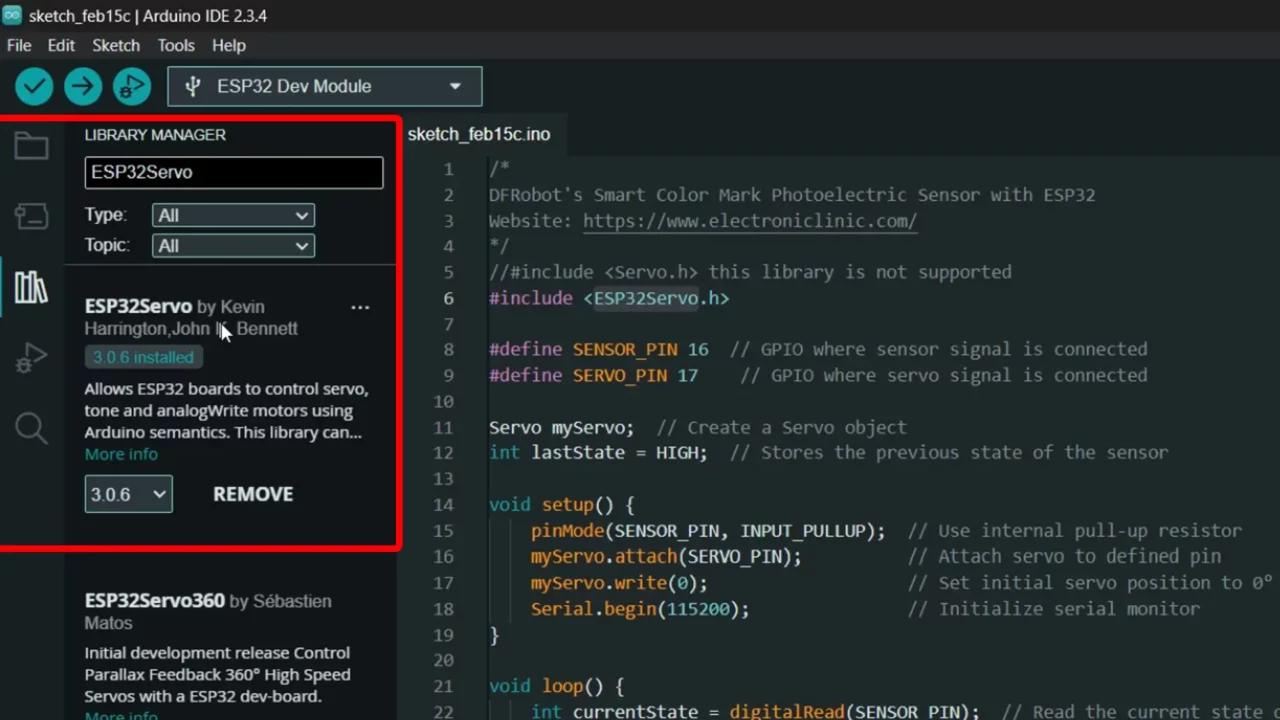
The standard Servo library does not support ESP32. Instead, you should use the ESP32Servo library, which is designed specifically for ESP32-based boards.
Let me show you, how to install this library.
- Copy the library name.
- Then go to LIBRARY MANAGER and paste the library name.
- Make sure to install the ESP32Servo by Kevin. You can see I have already installed it.
The Color sensor is still connected to GPIO 16, and the servo motor is connected to GPIO 17. When the sensor detects an object (LOW state), the servo moves to 90°. When the object is no longer detected (HIGH state), the servo returns to 0°. The previous sensor state is stored to detect transitions accurately. The detection events are also printed to the serial monitor for debugging purposes. The loop continuously monitors the sensor and updates the servo position accordingly.
|
1 2 3 4 5 6 7 8 9 10 11 12 13 14 15 16 17 18 19 20 21 22 23 24 25 26 27 28 29 30 31 32 33 34 35 36 37 |
/* DFRobot's Smart Color Mark Photoelectric Sensor with ESP32 Website: https://www.electroniclinic.com/ */ #include <ESP32Servo.h> #define SENSOR_PIN 16 // GPIO where sensor signal is connected #define SERVO_PIN 17 // GPIO where servo signal is connected Servo myServo; // Create a Servo object int lastState = HIGH; // Stores the previous state of the sensor void setup() { pinMode(SENSOR_PIN, INPUT_PULLUP); // Use internal pull-up resistor myServo.attach(SERVO_PIN); // Attach servo to defined pin myServo.write(0); // Set initial servo position to 0° Serial.begin(115200); // Initialize serial monitor } void loop() { int currentState = digitalRead(SENSOR_PIN); // Read the current state of the sensor // Check if the signal has transitioned from HIGH to LOW (detection event) if (lastState == HIGH && currentState == LOW) { Serial.println("Signal Detected! Moving Servo to 90°"); myServo.write(90); // Move servo to 90° } // Check if the signal transitions back to HIGH if (lastState == LOW && currentState == HIGH) { Serial.println("No Signal! Moving Servo back to 0°"); myServo.write(0); // Move servo back to 0° } lastState = currentState; // Update last state for next loop iteration } |
Practical Demonstration:
In the image below, you can see when there is no white colored object under the color sensor; the Servo stays at 0 degrees.

As soon as the sensor detects the White color the Servo arm moves to 90 degrees.
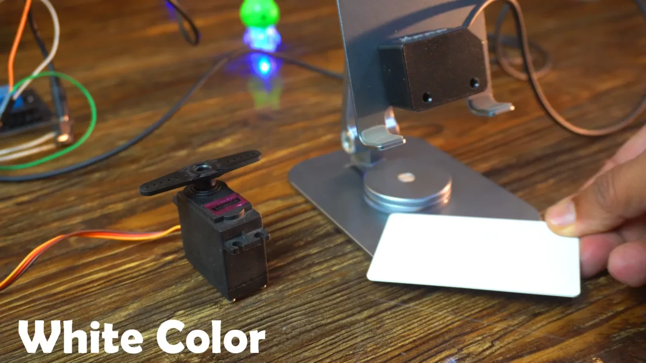
It’s not that you can only use the white color; you can use any color you want. Just make sure that:
Screen colors cannot be detected.
Light colors cannot be detected.
Liquid colors cannot be detected.
Now, let’s control the servo using a blue color keychain. For this, we first need to set the blue color, just like we did with the white color.
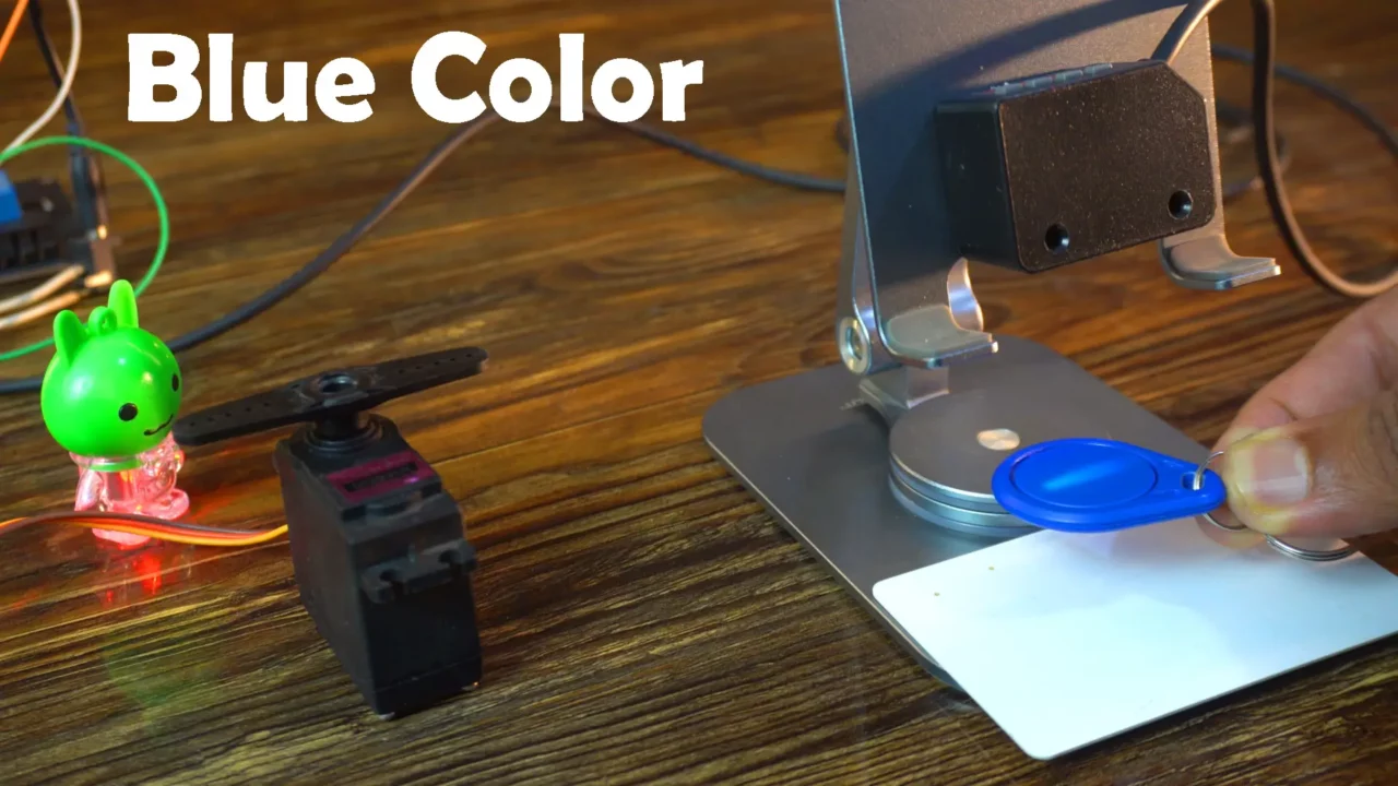
It successfully detected the Blue Color and the ESP32 moved the Servo arm to 90 degrees. Personally, I had never used such an amazing color sensor before. This Smart Color Mark Photoelectric Sensor by the DFRobot is really worth giving a try.
So, that’s all for now.
Watch Video Tutorial:

Discover more from Electronic Clinic
Subscribe to get the latest posts sent to your email.


