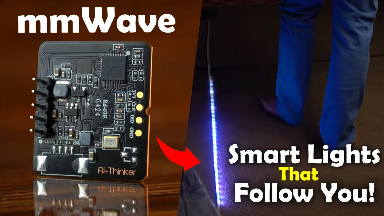
Smart Staircase Lighting with ESP32 and mmWave Sensor | Motion-Activated LED Strip
Last Updated on March 10, 2025 by Engr. Shahzada Fahad
Table of Contents
Smart Staircase Lighting:
Smart Staircase Lighting with ESP32 and mmWave Sensor | Motion-Activated LED Strip- Since I published an article on the RD-03E mmWave Radar module, many people have requested that I use this sensor in a home automation project.
So today, let’s build a smart staircase lighting control system using the ESP32 WiFi + Bluetooth module, RD-03E mmWave sensor, and WS2811 RGB LED strip.
In this project, lights will move along with the person, making it an intermediate-level project. That’s why we will follow a step-by-step approach:
- First, we will install the required libraries and learn how to control the RGB LED strip.
- In Example 2, we will integrate hand gesture recognition, allowing us to switch between different colors without touching any buttons.
- In Example 3, we’ll turn the RGB LED strip ON/OFF based on a person’s distance from the mmWave Radar module.
- Finally, in Example 4, we are going to create a dynamic lighting system where the WS2811 RGB LED strip will light up and move along with the person as they approach or move away from the RD-03E mmWave Sensor.
So, without any further delay let’s get started!!!
Amazon Links:
Other Tools and Components:
ESP32 WiFi + Bluetooth Module (Recommended)
Arduino Nano USB C type (Recommended)
*Please Note: These are affiliate links. I may make a commission if you buy the components through these links. I would appreciate your support in this way!
Before starting the projects, let me tell you that I have already made detailed getting started videos on the RD-03E mmWave Sensor, WS2811 RGB LED Strip, and the ESP32 Development Board, which are available on my YouTube channel “Electronic Clinic”.
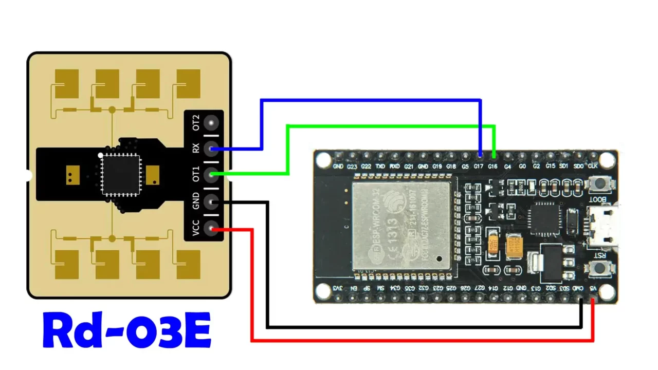
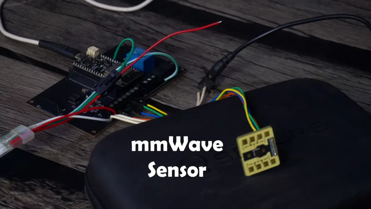
RD-03E mmWave Sensor Interfacing:
Connect the OT1 and RX pins of RD-03E mmWave sensor to the ESP32 GPIO’s 16 and 17 respectively. And connect the VCC and GND pins to the 5V and GND pins on the ESP32. For the wiring you can follow this circuit diagram.
WS2811 RGB LED Strip Interfacing:
Connect the RED and WHITE wires of the WS2811 RGB LED Strip to the 12V power supply. And also connect its ground wire to the ESP32 ground. All the grounds should be connected together.
And connect the Data-in wire to the ESP32 GPIO 12.
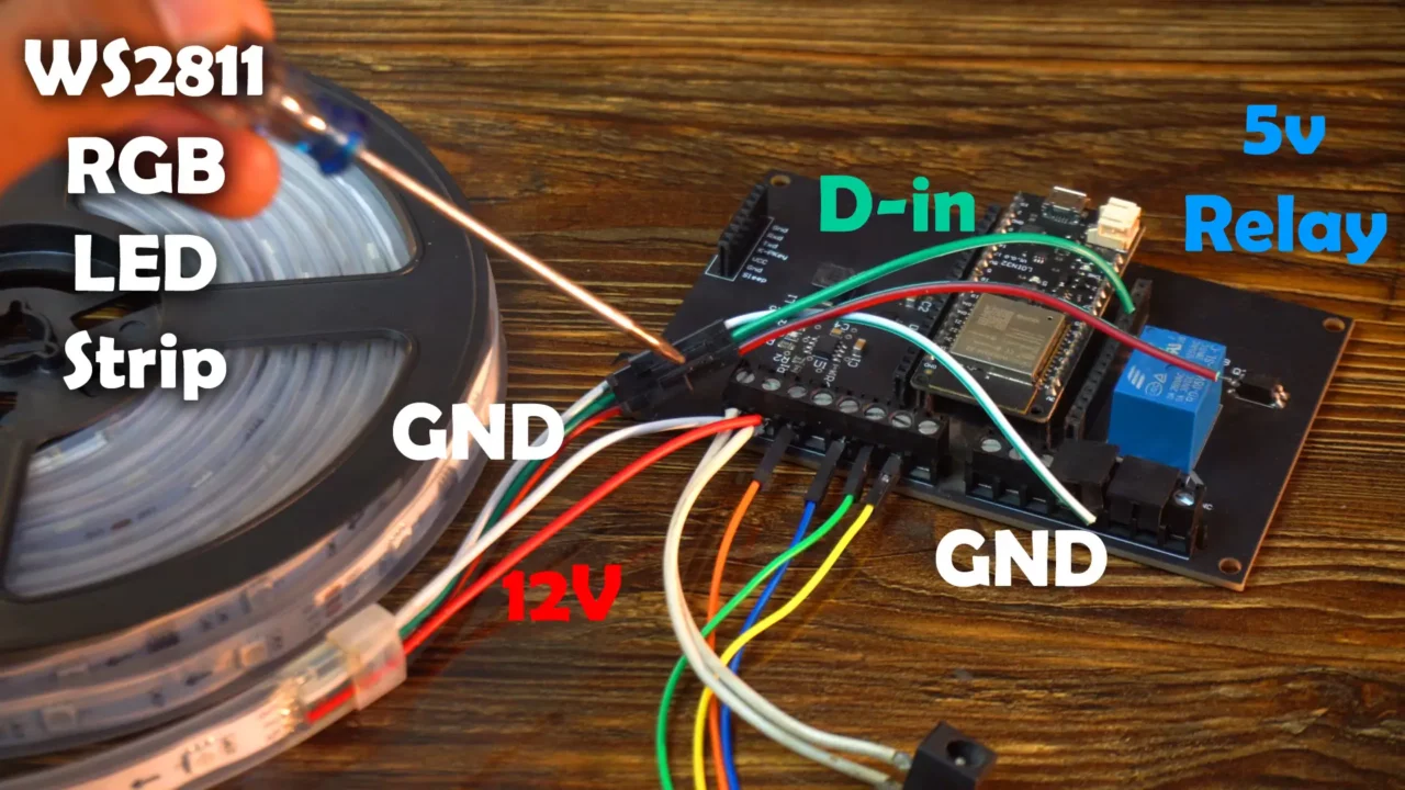
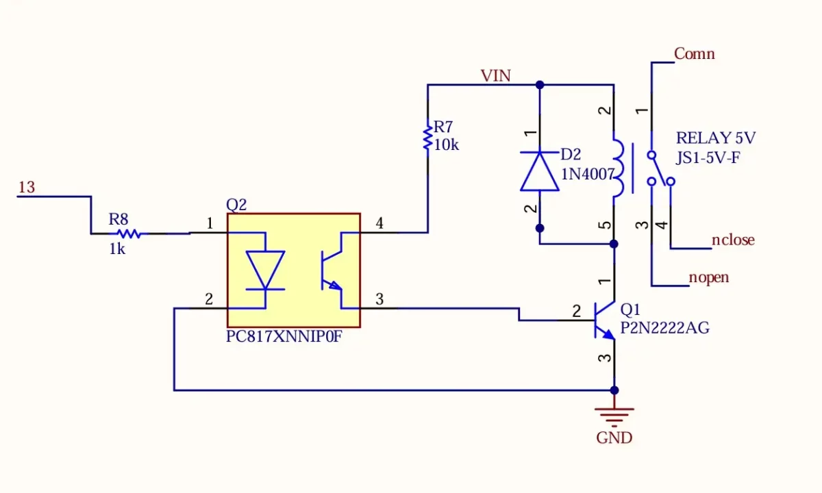
5V Relay interfacing:
On this ESP32 development board, you can see I have also a 5V SPDT type relay. Its connected to the GPIO 13 on the ESP32. For the relay wiring you can follow this circuit diagram.
I have already explained the sensor orientation and installation in great detail in my first article on the RD-03E mmWave Radar module.
Anyways, this basic setup is sufficient for me. So, let’s go ahead and start with our first example.
Example 1: ESP32 & WS2811 RGB LED Strip
The purpose of Example 1 is to control an RGB LED strip using the ESP32.
In this example, we are not using the mmWave sensor.
For projects that involve multiple components, the best approach is to get each component working individually first and then, in the end, combine everything into the final code.
Programming:
First of all, you need to install the FastLED library in the Arduino IDE. For this,
- Copy the library name and
- Then go to the LIBRARY MANAGER and
- Paste the library name.
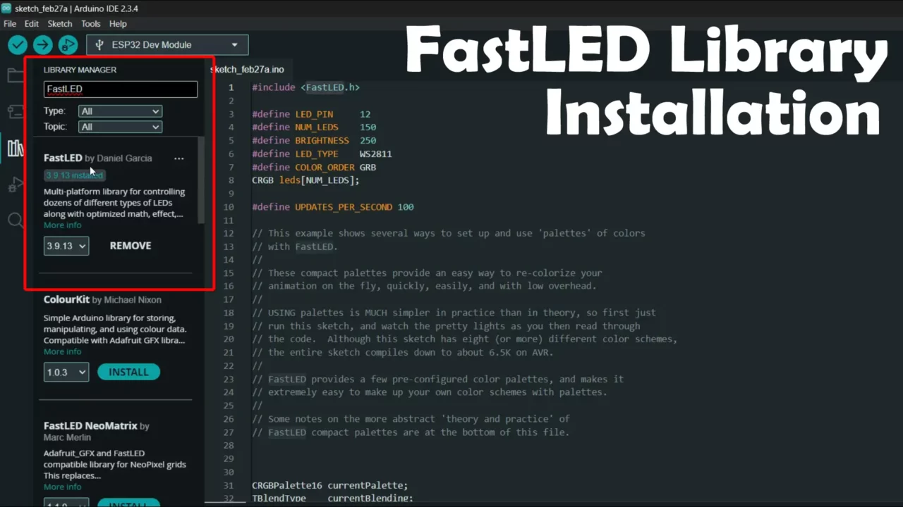
You can see, I have already installed this library make sure to install the latest version.
ESP32 RGB LED Strip Code:
This is the same code, I used with the Arduino. I only changed the pin number. Rest of the code is exactly the same, I didn’t even change a single line of code.
|
1 2 3 4 5 6 7 8 9 10 11 12 13 14 15 16 17 18 19 20 21 22 23 24 25 26 27 28 29 30 31 32 33 34 35 36 37 38 39 40 41 42 43 44 45 46 47 48 49 50 51 52 53 54 55 56 57 58 59 60 61 62 63 64 65 66 67 68 69 70 71 72 73 74 75 76 77 78 79 80 81 82 83 84 85 86 87 88 89 90 91 92 93 94 95 96 97 98 99 100 101 102 103 104 105 106 107 108 109 110 111 112 113 114 115 116 117 118 119 120 121 122 123 124 125 126 127 128 129 130 131 132 133 134 135 136 137 138 139 140 141 142 143 144 145 146 147 148 149 150 151 152 153 154 155 156 157 158 159 160 161 162 163 164 165 166 167 168 169 170 171 172 173 174 175 176 177 178 179 180 181 182 183 184 185 186 187 188 |
#include <FastLED.h> #define LED_PIN 12 #define NUM_LEDS 150 #define BRIGHTNESS 250 #define LED_TYPE WS2811 #define COLOR_ORDER GRB CRGB leds[NUM_LEDS]; #define UPDATES_PER_SECOND 100 // This example shows several ways to set up and use 'palettes' of colors // with FastLED. // // These compact palettes provide an easy way to re-colorize your // animation on the fly, quickly, easily, and with low overhead. // // USING palettes is MUCH simpler in practice than in theory, so first just // run this sketch, and watch the pretty lights as you then read through // the code. Although this sketch has eight (or more) different color schemes, // the entire sketch compiles down to about 6.5K on AVR. // // FastLED provides a few pre-configured color palettes, and makes it // extremely easy to make up your own color schemes with palettes. // // Some notes on the more abstract 'theory and practice' of // FastLED compact palettes are at the bottom of this file. CRGBPalette16 currentPalette; TBlendType currentBlending; extern CRGBPalette16 myRedWhiteBluePalette; extern const TProgmemPalette16 myRedWhiteBluePalette_p PROGMEM; void setup() { delay( 3000 ); // power-up safety delay FastLED.addLeds<LED_TYPE, LED_PIN, COLOR_ORDER>(leds, NUM_LEDS).setCorrection( TypicalLEDStrip ); FastLED.setBrightness( BRIGHTNESS ); currentPalette = RainbowColors_p; currentBlending = LINEARBLEND; } void loop() { ChangePalettePeriodically(); static uint8_t startIndex = 0; startIndex = startIndex + 1; /* motion speed */ FillLEDsFromPaletteColors( startIndex); FastLED.show(); FastLED.delay(1000 / UPDATES_PER_SECOND); } void FillLEDsFromPaletteColors( uint8_t colorIndex) { uint8_t brightness = 255; for( int i = 0; i < NUM_LEDS; ++i) { leds[i] = ColorFromPalette( currentPalette, colorIndex, brightness, currentBlending); colorIndex += 3; } } // There are several different palettes of colors demonstrated here. // // FastLED provides several 'preset' palettes: RainbowColors_p, RainbowStripeColors_p, // OceanColors_p, CloudColors_p, LavaColors_p, ForestColors_p, and PartyColors_p. // // Additionally, you can manually define your own color palettes, or you can write // code that creates color palettes on the fly. All are shown here. void ChangePalettePeriodically() { uint8_t secondHand = (millis() / 1000) % 60; static uint8_t lastSecond = 99; if( lastSecond != secondHand) { lastSecond = secondHand; if( secondHand == 0) { currentPalette = RainbowColors_p; currentBlending = LINEARBLEND; } if( secondHand == 10) { currentPalette = RainbowStripeColors_p; currentBlending = NOBLEND; } if( secondHand == 15) { currentPalette = RainbowStripeColors_p; currentBlending = LINEARBLEND; } if( secondHand == 20) { SetupPurpleAndGreenPalette(); currentBlending = LINEARBLEND; } if( secondHand == 25) { SetupTotallyRandomPalette(); currentBlending = LINEARBLEND; } if( secondHand == 30) { SetupBlackAndWhiteStripedPalette(); currentBlending = NOBLEND; } if( secondHand == 35) { SetupBlackAndWhiteStripedPalette(); currentBlending = LINEARBLEND; } if( secondHand == 40) { currentPalette = CloudColors_p; currentBlending = LINEARBLEND; } if( secondHand == 45) { currentPalette = PartyColors_p; currentBlending = LINEARBLEND; } if( secondHand == 50) { currentPalette = myRedWhiteBluePalette_p; currentBlending = NOBLEND; } if( secondHand == 55) { currentPalette = myRedWhiteBluePalette_p; currentBlending = LINEARBLEND; } } } // This function fills the palette with totally random colors. void SetupTotallyRandomPalette() { for( int i = 0; i < 16; ++i) { currentPalette[i] = CHSV( random8(), 255, random8()); } } // This function sets up a palette of black and white stripes, // using code. Since the palette is effectively an array of // sixteen CRGB colors, the various fill_* functions can be used // to set them up. void SetupBlackAndWhiteStripedPalette() { // 'black out' all 16 palette entries... fill_solid( currentPalette, 16, CRGB::Black); // and set every fourth one to white. currentPalette[0] = CRGB::White; currentPalette[4] = CRGB::White; currentPalette[8] = CRGB::White; currentPalette[12] = CRGB::White; } // This function sets up a palette of purple and green stripes. void SetupPurpleAndGreenPalette() { CRGB purple = CHSV( HUE_PURPLE, 255, 255); CRGB green = CHSV( HUE_GREEN, 255, 255); CRGB black = CRGB::Black; currentPalette = CRGBPalette16( green, green, black, black, purple, purple, black, black, green, green, black, black, purple, purple, black, black ); } // This example shows how to set up a static color palette // which is stored in PROGMEM (flash), which is almost always more // plentiful than RAM. A static PROGMEM palette like this // takes up 64 bytes of flash. const TProgmemPalette16 myRedWhiteBluePalette_p PROGMEM = { CRGB::Red, CRGB::Gray, // 'white' is too bright compared to red and blue CRGB::Blue, CRGB::Black, CRGB::Red, CRGB::Gray, CRGB::Blue, CRGB::Black, CRGB::Red, CRGB::Red, CRGB::Gray, CRGB::Gray, CRGB::Blue, CRGB::Blue, CRGB::Black, CRGB::Black }; // Additional notes on FastLED compact palettes: // // Normally, in computer graphics, the palette (or "color lookup table") // has 256 entries, each containing a specific 24-bit RGB color. You can then // index into the color palette using a simple 8-bit (one byte) value. // A 256-entry color palette takes up 768 bytes of RAM, which on Arduino // is quite possibly "too many" bytes. // // FastLED does offer traditional 256-element palettes, for setups that // can afford the 768-byte cost in RAM. // // However, FastLED also offers a compact alternative. FastLED offers // palettes that store 16 distinct entries, but can be accessed AS IF // they actually have 256 entries; this is accomplished by interpolating // between the 16 explicit entries to create fifteen intermediate palette // entries between each pair. // // So for example, if you set the first two explicit entries of a compact // palette to Green (0,255,0) and Blue (0,0,255), and then retrieved // the first sixteen entries from the virtual palette (of 256), you'd get // Green, followed by a smooth gradient from green-to-blue, and then Blue. |
ESP32 and RGB LED Strip in Action:
As you can see, we are successfully controlling the WS2811 RGB LED Strip using the ESP32.
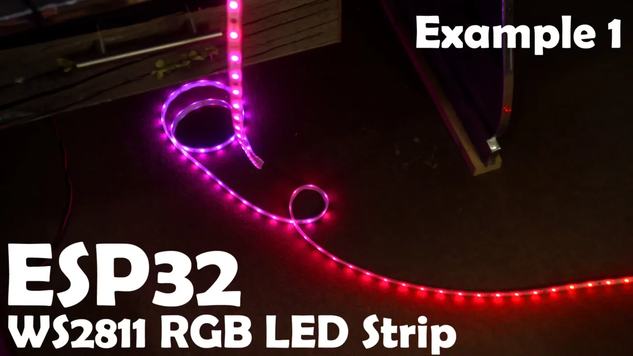
This means that both our wiring and code are working correctly. Now, we can move on to Example 2.
Example 2: RGB LED Strip Color Change using mmWave Sensor
In Example 2, we will control the RGB LED strip using hand gestures with the RD-03E mmWave Radar module.
Color Change Code:
|
1 2 3 4 5 6 7 8 9 10 11 12 13 14 15 16 17 18 19 20 21 22 23 24 25 26 27 28 29 30 31 32 33 34 35 36 37 38 39 40 41 42 43 44 45 46 47 48 49 50 51 52 53 54 55 56 57 58 59 60 61 62 63 64 65 66 67 68 69 70 71 72 73 74 75 76 77 78 79 80 81 82 83 |
#include <HardwareSerial.h> #include <FastLED.h> #define RX_PIN 16 // Replace with your actual RX pin #define TX_PIN 17 // Replace with your actual TX pin HardwareSerial radarSerial(1); // Use Serial1 for the RD-03E radar module #define LED_PIN 12 // WS2811 LED strip pin #define NUM_LEDS 150 #define BRIGHTNESS 250 #define LED_TYPE WS2811 #define COLOR_ORDER GRB CRGB leds[NUM_LEDS]; int colorIndex = 0; // Track the current color // Define an array of colors to cycle through CRGB colorList[] = { CRGB::Red, CRGB::Green, CRGB::Blue, CRGB::Yellow, CRGB::Purple, CRGB::Cyan, CRGB::White }; const int numColors = sizeof(colorList) / sizeof(colorList[0]); void setup() { Serial.begin(115200); radarSerial.begin(256000, SERIAL_8N1, RX_PIN, TX_PIN); delay(1000); FastLED.addLeds<LED_TYPE, LED_PIN, COLOR_ORDER>(leds, NUM_LEDS); FastLED.setBrightness(BRIGHTNESS); FastLED.clear(); FastLED.show(); } void readDistanceAndGesture() { static bool headerDetected = false; static uint8_t frameData[5]; int byteIndex = 0; while (radarSerial.available()) { uint8_t byte = radarSerial.read(); if (!headerDetected && byte == 0xAA) { headerDetected = true; frameData[0] = byte; byteIndex = 1; } else if (headerDetected) { frameData[byteIndex++] = byte; if (byteIndex == 5) { headerDetected = false; if (frameData[4] == 0x55) { uint16_t distance = frameData[1] | (frameData[2] << 8); uint8_t gesture = frameData[3]; if (gesture == 0x01) { // Gesture detected colorIndex = (colorIndex + 1) % numColors; // Cycle through colors fill_solid(leds, NUM_LEDS, colorList[colorIndex]); FastLED.show(); Serial.print("Changed to color: "); Serial.println(colorIndex); } Serial.print("Distance: "); Serial.print(distance); Serial.print(" cm "); Serial.print("Current Color Index: "); Serial.println(colorIndex); } else { Serial.println("Invalid frame received (Footer mismatch)."); } } } } } void loop() { readDistanceAndGesture(); delay(100); } |
RGB LED Strip Color Change Code Explanation:
|
1 2 |
#include <HardwareSerial.h> #include <FastLED.h> |
First, we include HardwareSerial header to communicate with the RD-03E mmWave sensor.
Then, we bring in FastLED library to control the WS2811 RGB LED strip.
Defining Serial Communication Pins
|
1 2 |
#define RX_PIN 16 // Replace with your actual RX pin #define TX_PIN 17 // Replace with your actual TX pin |
The mmWave sensor sends data over UART (Serial).
We define which ESP32 pins will receive (RX) and transmit (TX) data.
|
1 |
HardwareSerial radarSerial(1); // Use Serial1 for the RD-03E radar module |
We create a HardwareSerial object to handle communication with the sensor.
The (1) means we are using **Serial1** (not the default Serial0).
Setting Up the LED Strip
|
1 2 3 4 5 6 7 8 |
#define LED_PIN 12 // WS2811 LED strip pin #define NUM_LEDS 150 #define BRIGHTNESS 250 #define LED_TYPE WS2811 #define COLOR_ORDER GRB CRGB leds[NUM_LEDS]; // Array to hold LED colors int colorIndex = 0; // Tracks the current color |
We create an **array** to store the LED colors.
colorIndex helps us keep track of which color is currently active.
Defining Colors
|
1 2 3 4 5 |
CRGB colorList[] = { CRGB::Red, CRGB::Green, CRGB::Blue, CRGB::Yellow, CRGB::Purple, CRGB::Cyan, CRGB::White }; const int numColors = sizeof(colorList) / sizeof(colorList[0]); |
We create an **array of colors** (Red, Green, Blue, etc.).
numColors calculates how many colors we have in colorList.
Setup Function (Runs Once)
|
1 2 3 4 5 6 7 8 9 10 |
void setup() { Serial.begin(115200); // Debugging serial monitor radarSerial.begin(256000, SERIAL_8N1, RX_PIN, TX_PIN); // Start radar sensor at 256000 baud rate delay(1000); // Give some time for everything to start FastLED.addLeds<LED_TYPE, LED_PIN, COLOR_ORDER>(leds, NUM_LEDS); FastLED.setBrightness(BRIGHTNESS); FastLED.clear(); FastLED.show(); } |
Starts the **Serial monitor** for debugging.
Initializes the **RD-03E sensor** at a high baud rate (256000).
Sets up the **LED strip**, applies brightness, clears it, and updates.
Reading Data from the Sensor
|
1 2 3 4 |
void readDistanceAndGesture() { static bool headerDetected = false; static uint8_t frameData[5]; int byteIndex = 0; |
headerDetected ensures we only process valid sensor data.
frameData[5] will store **5 bytes** from the radar module.
byteIndex keeps track of received bytes.
|
1 2 3 4 5 6 |
Loop Function (Runs Repeatedly) void loop() { readDistanceAndGesture(); delay(100); } |
Calls readDistanceAndGesture() every 100ms.
Keeps checking for new radar data and updating the LED strip.
Practical demonstration:
Just by using hand gestures, I can switch between colors; there’s no need to press any button.
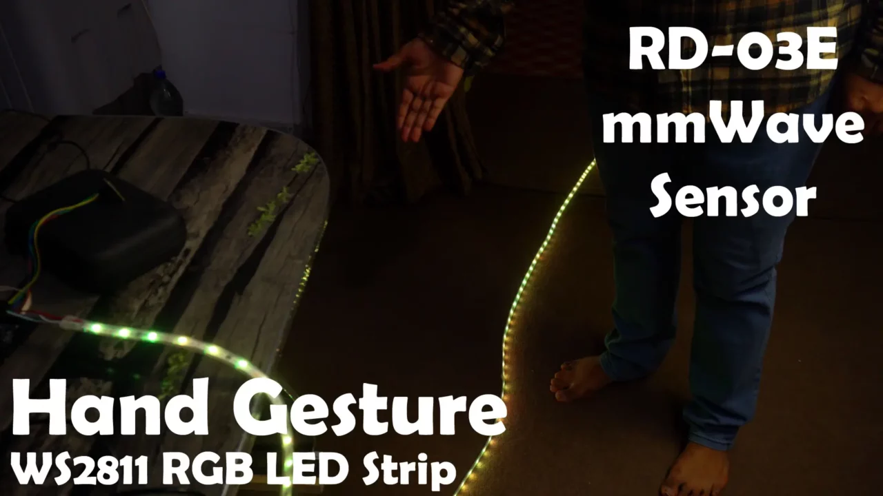
Simply moving my hand up and down in front of the mmWave sensor allows me to change the colors.
Example 3: Staircase RGB LED Strip and mmWave Sensor
In Example 3, we will turn the RGB LED strip ON/OFF based on a person’s distance.
Let’s imagine that this LED strip is installed on a staircase. When someone enters the sensor’s range, the LED strip will turn ON; otherwise, it will remain OFF.
Additionally, we will use hand gesture to control a relay, which can be used to switch other loads as well.
Staircase RGB LED Strip Code:
I have made some changes to the code. If you carefully study it, you will understand how it works.
|
1 2 3 4 5 6 7 8 9 10 11 12 13 14 15 16 17 18 19 20 21 22 23 24 25 26 27 28 29 30 31 32 33 34 35 36 37 38 39 40 41 42 43 44 45 46 47 48 49 50 51 52 53 54 55 56 57 58 59 60 61 62 63 64 65 66 67 68 69 70 71 72 73 74 75 76 77 78 79 80 81 82 83 84 85 86 87 88 89 90 91 92 93 94 95 96 97 98 99 100 101 102 103 104 105 106 107 108 109 110 111 112 113 114 115 |
#include <HardwareSerial.h> #include <FastLED.h> #define RX_PIN 16 // Replace with your actual RX pin #define TX_PIN 17 // Replace with your actual TX pin HardwareSerial radarSerial(1); // Use Serial1 for the RD-03E radar module #define LED_PIN 12 // WS2811 LED strip pin #define NUM_LEDS 150 #define BRIGHTNESS 250 #define LED_TYPE WS2811 #define COLOR_ORDER GRB #define CONTROL_PIN 13 // GPIO 13 for external device control CRGB leds[NUM_LEDS]; bool ledState = false; // Track LED strip state bool gpioState = false; // Track GPIO 13 state unsigned long lastLedToggleTime = 0; // Timer for LED strip control const unsigned long ledCheckInterval = 2000; // 2 seconds interval void setup() { Serial.begin(115200); radarSerial.begin(256000, SERIAL_8N1, RX_PIN, TX_PIN); delay(1000); FastLED.addLeds<LED_TYPE, LED_PIN, COLOR_ORDER>(leds, NUM_LEDS); FastLED.setBrightness(BRIGHTNESS); FastLED.clear(); FastLED.show(); pinMode(CONTROL_PIN, OUTPUT); digitalWrite(CONTROL_PIN, LOW); // Initialize GPIO 13 to OFF } void readDistanceAndGesture() { static bool headerDetected = false; static uint8_t frameData[5]; int byteIndex = 0; static bool personDetected = false; static unsigned long ledOnStartTime = 0; // Time when LEDs turned on while (radarSerial.available()) { uint8_t byte = radarSerial.read(); if (!headerDetected && byte == 0xAA) { headerDetected = true; frameData[0] = byte; byteIndex = 1; } else if (headerDetected) { frameData[byteIndex++] = byte; if (byteIndex == 5) { headerDetected = false; if (frameData[4] == 0x55) { uint16_t distance = frameData[1] | (frameData[2] << 8); uint8_t gesture = frameData[3]; // Toggle GPIO 13 on gesture detection (0x01) if (gesture == 0x01) { gpioState = !gpioState; digitalWrite(CONTROL_PIN, gpioState ? HIGH : LOW); Serial.print("GPIO 13 is now "); Serial.println(gpioState ? "ON" : "OFF"); } // LED Strip Control with Timer Logic unsigned long currentMillis = millis(); if (distance >= 50 && distance <= 300) { // Within 0.4m to 3m if (!ledState) { // Turn ON if not already ON ledState = true; fill_solid(leds, NUM_LEDS, CRGB::Blue); FastLED.show(); ledOnStartTime = currentMillis; // Start ON timer Serial.println("LED Strip turned ON (0.4m ≤ Distance ≤ 3m)"); } personDetected = true; } else { // Out of range (less than 0.4m or more than 3m) personDetected = false; } // If LEDs are ON, check every 2 seconds if the person is still in range if (ledState && (currentMillis - ledOnStartTime >= ledCheckInterval)) { if (!personDetected) { // If person is out of range, turn OFF ledState = false; FastLED.clear(); FastLED.show(); Serial.println("LED Strip turned OFF (Out of range for 2s)"); } else { ledOnStartTime = currentMillis; // Reset timer if still detected } } Serial.print("Distance: "); Serial.print(distance); Serial.print(" cm "); Serial.print("LED Strip is "); Serial.println(ledState ? "ON" : "OFF"); } else { Serial.println("Invalid frame received (Footer mismatch)."); } } } } } void loop() { readDistanceAndGesture(); } |
Staircase RGB LED Strip Code Explanation:
- Include Libraries
HardwareSerial Used for Serial communication with the RD-03E radar module.
FastLED Used to control the WS2811 RGB LED strip.
- Define Pins and Variables
RX (16) and TX (17) are used for radar module communication.
LED_PIN (12) controls the WS2811 LED strip.
CONTROL_PIN (13) is used to toggle an external device.
Various flags and timers are defined to handle LED and device control logic.
- Setup Function
Initializes Serial communication.
Sets up the FastLED library for LED strip control.
Configures GPIO 13 as an output.
- readDistanceAndGesture() Function
Reads data from the RD-03E mmWave sensor.
Extracts distance and gesture information.
If a gesture (0x01) is detected, toggles GPIO 13.
If a person is detected within the 0.4m – 3m range, turns the LED strip ON.
If the person moves out of range for 2 seconds, turns the LED strip OFF.
- Loop Function
Calls readDistanceAndGesture() repeatedly to continuously process sensor data.
Practical demonstration:
As you can see, as soon as I enter the pre-defined range, the RGB LED strip automatically turns ON and stays ON as long as I remain within the specified range. When I move out of the sensor’s range, the LED strip automatically turns OFF.
I have tested this multiple times, and there was no false triggering. For best sensor performance, make sure to fix the mmWave sensor securely to prevent any vibrations.
I also controlled the relay using hand gesture and it worked exceptionally well, you can watch it in the video given below.
Now, let’s move on to Example 4.
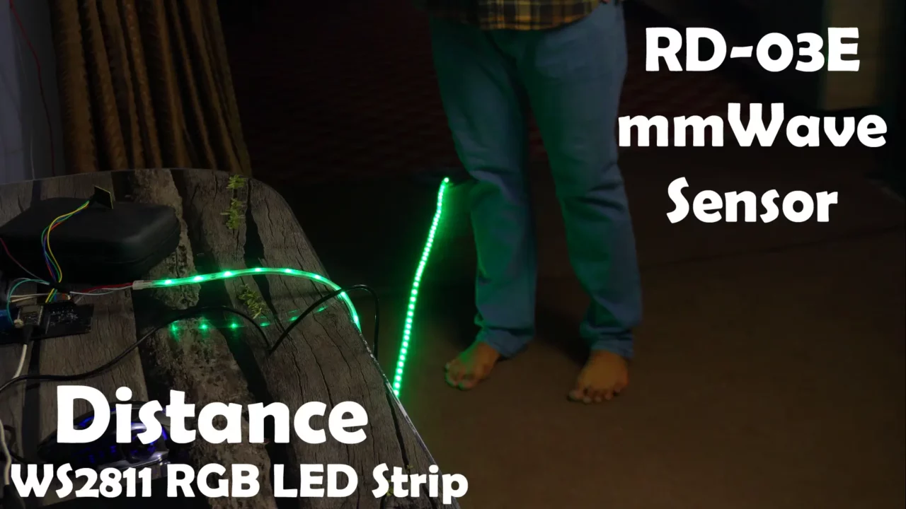
Example 4: Smart Staircase Lighting
In this 4th and final example, we will make the LEDs follow the person’s movement, creating an animation effect that mimics a walking path illumination
Additionally, we will use hand gestures to activate and deactivate the LED strip. You will clearly understand everything during the practical demonstration. I highly recommend to watch the video given at the end of this article.
Smart Staircase Lighting Programming:
|
1 2 3 4 5 6 7 8 9 10 11 12 13 14 15 16 17 18 19 20 21 22 23 24 25 26 27 28 29 30 31 32 33 34 35 36 37 38 39 40 41 42 43 44 45 46 47 48 49 50 51 52 53 54 55 56 57 58 59 60 61 62 63 64 65 66 67 68 69 70 71 72 73 74 75 76 77 78 79 80 81 82 83 84 85 86 87 88 89 90 91 92 93 94 95 96 97 98 99 100 101 102 103 104 105 106 107 108 109 110 111 112 113 114 115 116 117 |
#include <HardwareSerial.h> #include <FastLED.h> #define RX_PIN 16 // RD-03E sensor RX pin #define TX_PIN 17 // RD-03E sensor TX pin HardwareSerial radarSerial(1); // Use Serial1 for the RD-03E radar module #define LED_PIN 12 // WS2811 LED strip pin #define NUM_LEDS 150 // Total LEDs in the strip #define IGNORE_LEDS 30 // Ignore first 30 LEDs behind the sensor #define ACTIVE_LEDS (NUM_LEDS - IGNORE_LEDS) // LEDs we will control #define BRIGHTNESS 250 #define LED_TYPE WS2811 #define COLOR_ORDER GRB #define BLIND_SPOT 50 // Ignore first 50 cm #define MIN_DISTANCE 51 // Start lighting LEDs after blind spot (0.51m) #define MAX_DISTANCE 233 // Max detection range (2.33m) #define STEP_SIZE 8 //Every 8 cm, turn on 1 more LED //Change this to set LED color CRGB ledColor = CRGB::White; // Options: CRGB::Blue, CRGB::Green, CRGB::White, CRGB::Red, etc. CRGB leds[NUM_LEDS]; bool ledsActive = false; //LED strip is initially OFF void setup() { Serial.begin(115200); radarSerial.begin(256000, SERIAL_8N1, RX_PIN, TX_PIN); delay(1000); FastLED.addLeds<LED_TYPE, LED_PIN, COLOR_ORDER>(leds, NUM_LEDS); FastLED.setBrightness(BRIGHTNESS); FastLED.clear(); FastLED.show(); } void readDistanceAndUpdateLEDs() { static bool headerDetected = false; static uint8_t frameData[5]; int byteIndex = 0; while (radarSerial.available()) { uint8_t byte = radarSerial.read(); if (!headerDetected && byte == 0xAA) { headerDetected = true; frameData[0] = byte; byteIndex = 1; } else if (headerDetected) { frameData[byteIndex++] = byte; if (byteIndex == 5) { headerDetected = false; if (frameData[4] == 0x55) { uint16_t distance = frameData[1] | (frameData[2] << 8); uint8_t gesture = frameData[3]; //Read gesture //Toggle LEDs ON/OFF using gesture (0x01) if (gesture == 0x01) { ledsActive = !ledsActive; Serial.println(ledsActive ? "Gesture Detected: LEDs ON" : "Gesture Detected: LEDs OFF"); if (!ledsActive) { // Turn OFF LEDs if deactivated FastLED.clear(); FastLED.show(); return; } } //Ignore blind spot (First 50 cm) if (distance < BLIND_SPOT || !ledsActive) { FastLED.clear(); FastLED.show(); Serial.println("LEDs OFF (Blind Spot or Deactivated)"); return; } //Convert distance to number of LEDs if (distance >= MIN_DISTANCE && distance <= MAX_DISTANCE) { int numLEDs = (distance - MIN_DISTANCE) / STEP_SIZE + 1; numLEDs = constrain(numLEDs, 0, ACTIVE_LEDS); FastLED.clear(); // Turn on LEDs sequentially based on distance for (int i = 0; i < numLEDs; i++) { int index = IGNORE_LEDS + i; if (index < NUM_LEDS) { leds[index] = ledColor; } } FastLED.show(); Serial.print("Distance: "); Serial.print(distance); Serial.print(" cm LEDs ON: "); Serial.println(numLEDs); } else { FastLED.clear(); FastLED.show(); Serial.println("LEDs OFF (Out of range)"); } } else { Serial.println("Invalid frame received (Footer mismatch)."); } } } } } void loop() { readDistanceAndUpdateLEDs(); } |
The code is a bit long, but I have added comments with instructions, so you shouldn’t have any difficulty understanding it.
there are a few variables I need to explain so that you don’t face any confusion.
|
1 |
#define IGNORE_LEDS 30 // Ignore first 30 LEDs behind the sensor |
Some LEDs are behind the sensor (not useful for lighting your path); so, this variable prevents those LEDs from being turned ON.
|
1 |
#define ACTIVE_LEDS (NUM_LEDS - IGNORE_LEDS) // LEDs we will control |
These are the remaining LEDs in front of the sensor that we will actually control.
|
1 |
BLIND_SPOT = 50 cm |
The RD-03E mmWave sensor cannot detect objects within the first 50 cm reliably.
Any distance below 50 cm is ignored.
|
1 |
MIN_DISTANCE = 51 cm |
The first LED turns ON at 51 cm (after the blind spot).
|
1 |
MAX_DISTANCE = 233 cm |
The maximum distance considered for LEDs control.
Any object beyond (233 cm) is ignored. You can increase or decrease this maximum distance value as per your needs.
|
1 |
STEP_SIZE = 8 cm |
For every 8 cm, one more LED lights up.
Now let’s watch the RD-03E mmWave Sensor and RGB LED strip based Smart Staircase Lighting control system in action.
Practical Demonstration:
As you can see, when I move in front of the sensor, the LED strip is not turning ON. This is because the LED strip is currently deactivated.
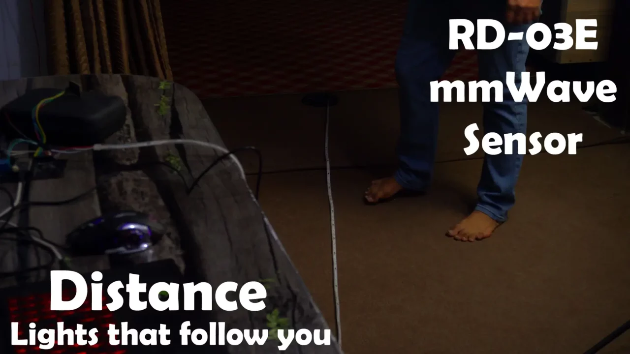
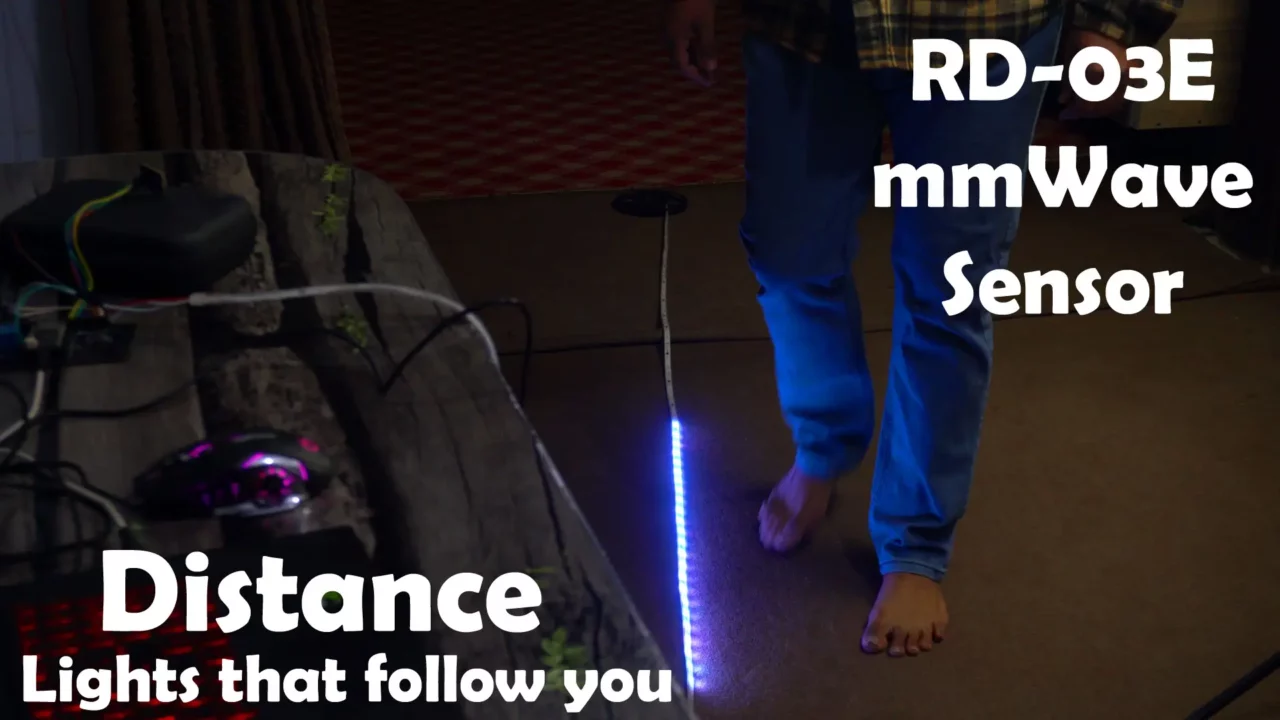
So, let’s turn it ON using a hand gesture.
Now, as I move forward and backward, the LEDs will turn ON/OFF accordingly.
You can modify the code as per your requirements. I’m sure you now understand how we can use the mmWave sensor to control RGB LED strips.
So, that’s all for now.
Watch Video Tutorial:

Discover more from Electronic Clinic
Subscribe to get the latest posts sent to your email.


