ESP32 Blynk Home Automation with MaTouch 1.28” Toolset Timer Switch Relay
Last Updated on September 29, 2025 by Engr. Shahzada Fahad
Table of Contents
Description:
ESP32 Blynk Home Automation with MaTouch 1.28” Toolset Timer Switch Relay- Imagine it’s a freezing winter night. You are already in bed, warm and comfortable, when you suddenly remember; the heater is still running, or the TV is still ON.
Now, you have two choices:
- Either get out of bed, walk all the way to the switchboard, and turn it OFF; or
- Simply grab your phone, tap a button, and it’s done!
That’s exactly what this project makes possible.
In my previous article, we explored how this amazing MaTouch 1.28” Toolset Timer Switch Relay from Makerfabs can completely replace a conventional switchboard.
We controlled relays using the on-screen UI designed in Squareline Studio, and we also used the encoder and physical buttons for quick access.
We even scheduled timers for automatic ON/OFF control of appliances.
That means you don’t always have to remember to press a button; your devices can turn ON or OFF at the exact time you want.
For example, you can set the heater to turn ON in the morning before you wake up, or have the lights turn OFF automatically at night.
But today, we are taking it to the next level.
This is Version 2 of the project.
And now, the same relays that we previously controlled through the UI; can also be controlled through the Blynk IoT application; from anywhere in the world!
That means you can control your home appliances directly from your smartphone, no matter where you are.
Think about it:
With this setup, you don’t need to worry about forgotten appliances.
Even if you leave home in a hurry and the Heater or TV or water pump is still ON, you can check the status on your phone and switch it OFF from anywhere.
Here is the part I really love;
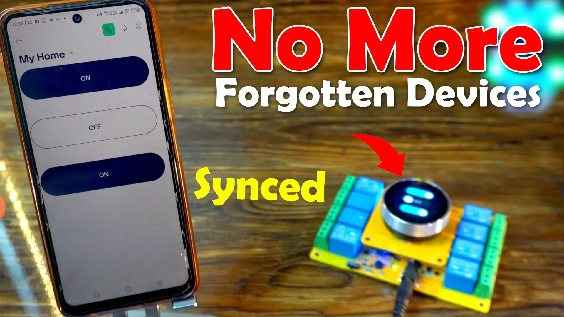
The UI and the Blynk application are perfectly synchronized.
For example:
If I turn ON a load from the display UI “User Interface”, the same switch will also turn ON in the Blynk app.
Similarly, if I turn ON/OFF any load from my phone, the switch will also update on the UI.
This way, I always know which loads are ON and which ones are OFF, no matter where they were controlled from.
And here’s another thing I have carefully taken care of;
What if WiFi goes down?
Normally, if we had used Blynk.begin(), the controller would just keep trying to connect to Blynk, and the UI would stop responding. That’s not good for home automation.
So instead, I used WiFi + Blynk, which ensures that:
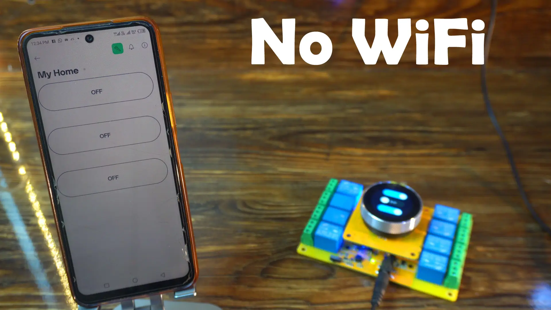
Even if WiFi is unavailable, the UI continues to work smoothly. Right now, on the display, I have turned ON all three switches, but in the Blynk application, the switches don’t update because the controller is disconnected from WiFi. The UI will continue to work, but it won’t send the switch status to the Blynk app.
And as soon as WiFi comes back, the controller reconnects to Blynk automatically. Normally, it takes a few seconds to update the switch status in the Blynk application.

This makes the system reliable both online and offline.

On this second screen, I am displaying the date and time, and I am using the same background image from the previous project.

This background adds a nice touch to the interface and makes it look more polished.
Of course, you can always customize it with your own designs, or even add animations if you want to make the UI more dynamic.
SquareLine Studio:
If you have read my previous articles on Squareline Studio and LVGL, then by now you already know how to start a new project or import an existing one in Squareline Studio.
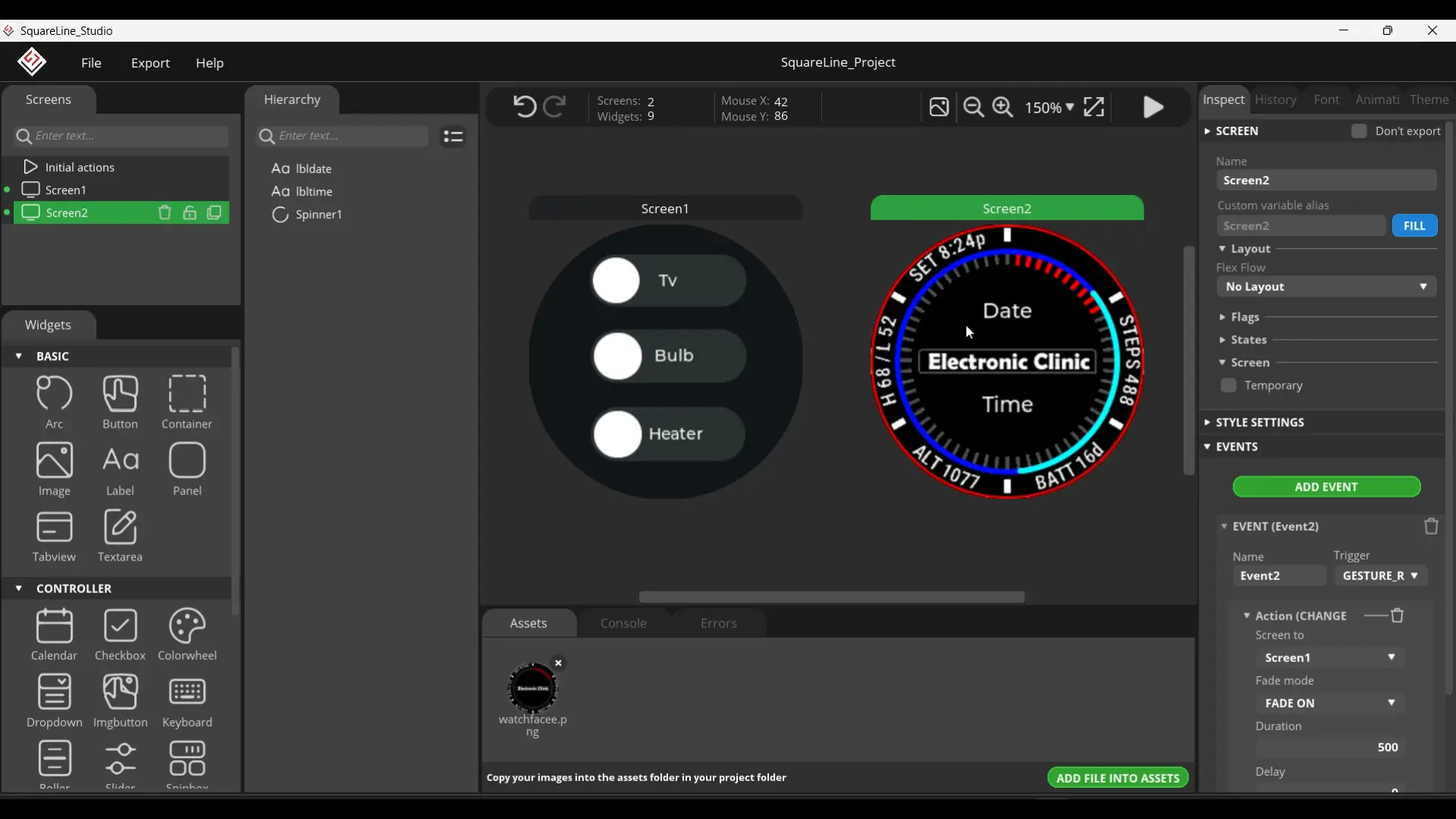
Now, on Screen2, we are displaying the Date and Time. For this, I have simply used two labels named lbldate and lbltime. I won’t go into too much detail here, because I have already explained this in my previous article.

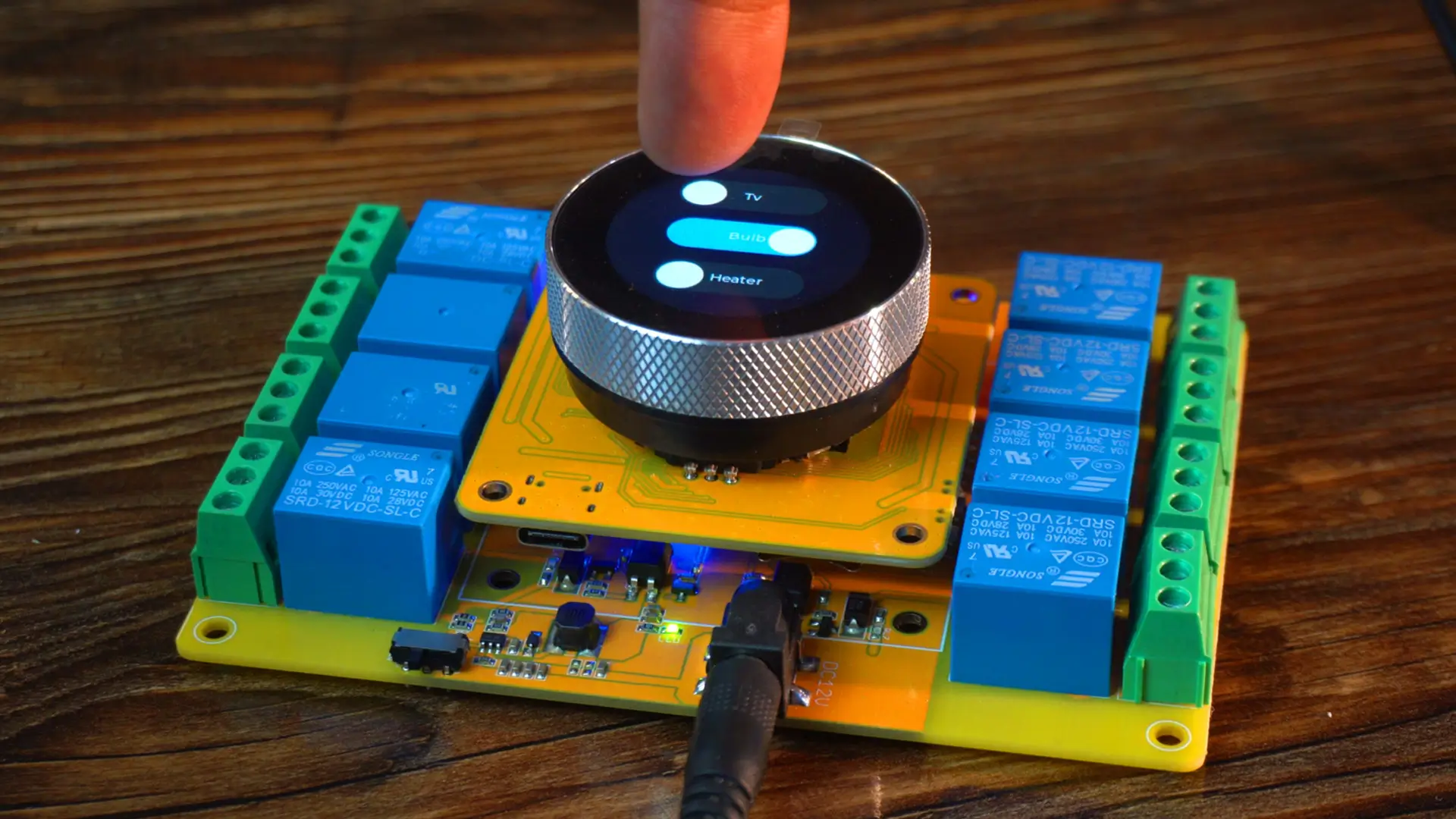
On Screen1, I have added three switches, and I have assigned events to each of them. For example, when I turn the TV switch ON or OFF, the tvfun function is called. In the same way, I have defined functions for the other two switches as well.
Now, let me show you what I have set up on the Blynk side.
Blynk side set up:
I have already written a getting started article on ESP32 and Blynk. So, if you are using Blynk for the very first time, I recommend reading that article first or you can also watch the video tutorial on my YouTube channel Electronic Clinic.

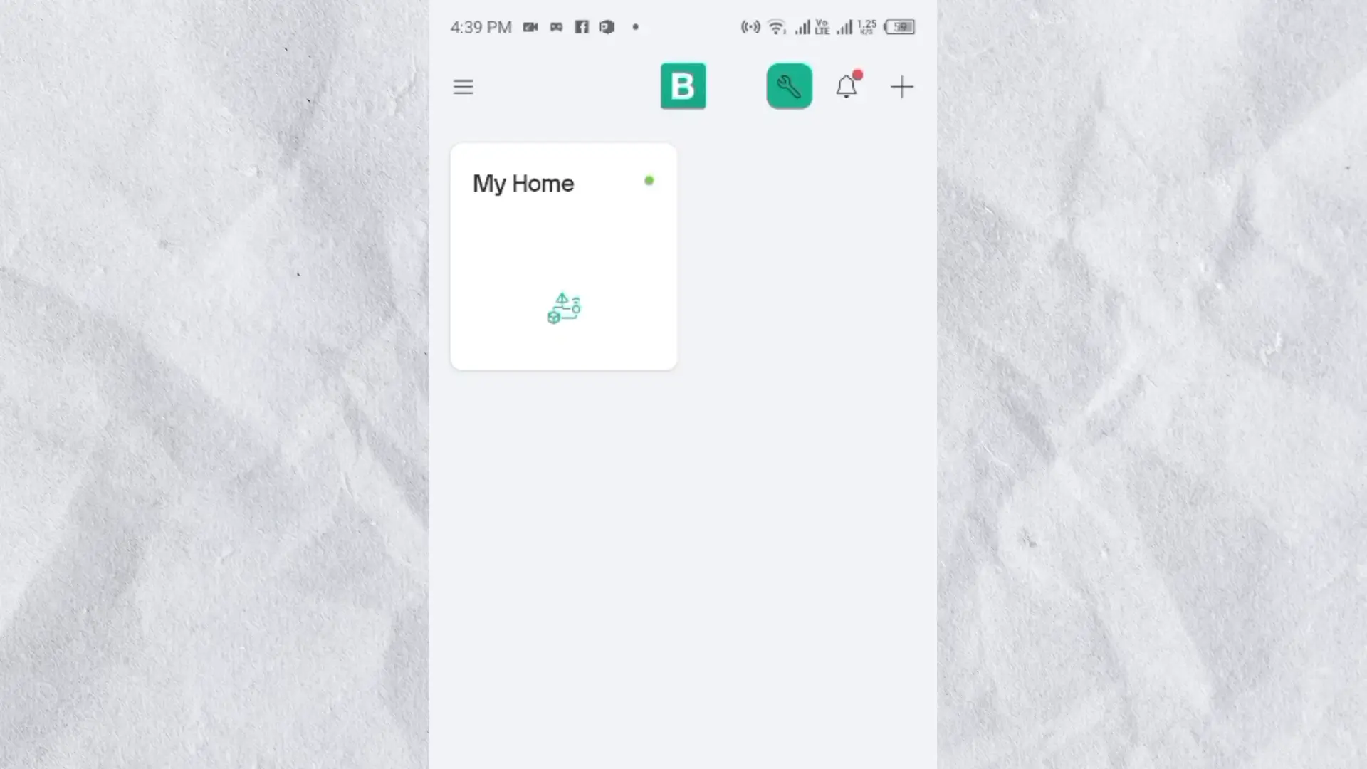
Anyway, as you can see, I have created a device named “My Home”, and it’s already online. Let’s go ahead and open it.

For this project, I am only using three switches, and I have kept their names the same as in the UI, so there is no confusion when controlling the loads.
Now, if you go to Developer Tools, you will find the Firmware Configuration.
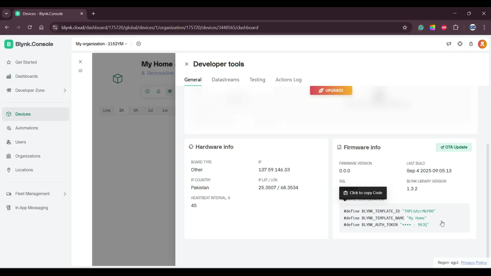
From here, you can simply copy that configuration and paste it at the top of your code.

Next, if I open the Datastreams, you can see I have added only three variables: relay1, relay2, and relay3.

Each one is linked to a virtual pin; V1, V2, and V3; and their data type is set as integer.
The reason we use virtual pins is that;
They make communication between the app and the ESP32 much easier and more flexible.
Instead of being limited to fixed hardware pins, virtual pins let us map any button or widget in Blynk to any function in our code.
This way, even if you change your hardware wiring later, you don’t need to redesign your app; you just adjust the code. It keeps things simple and very organized.
And that’s all we need to set up on the Blynk side.
Blynk IoT on Mobile:
When you open the Blynk app on your phone, you will see the device that you created earlier. In my case, it’s showing up as “My Home.”
If I open this device, you can see I have already added three switches, and I have assigned them to the same datastreams we just created.
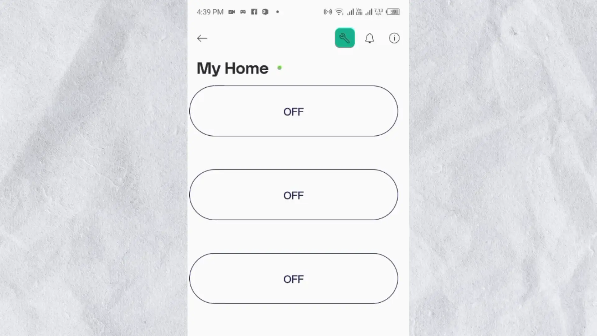
You can also see that the device is online and ready to use.
ESP32S3 Programming:
|
1 2 3 4 5 6 7 8 9 10 11 12 13 14 15 16 17 18 19 20 21 22 23 24 25 26 27 28 29 30 31 32 33 34 35 36 37 38 39 40 41 42 43 44 45 46 47 48 49 50 51 52 53 54 55 56 57 58 59 60 61 62 63 64 65 66 67 68 69 70 71 72 73 74 75 76 77 78 79 80 81 82 83 84 85 86 87 88 89 90 91 92 93 94 95 96 97 98 99 100 101 102 103 104 105 106 107 108 109 110 111 112 113 114 115 116 117 118 119 120 121 122 123 124 125 126 127 128 129 130 131 132 133 134 135 136 137 138 139 140 141 142 143 144 145 146 147 148 149 150 151 152 153 154 155 156 157 158 159 160 161 162 163 164 165 166 167 168 169 170 171 172 173 174 175 176 177 178 179 180 181 182 183 184 185 186 187 188 189 190 191 192 193 194 195 196 197 198 199 200 201 202 203 204 205 206 207 208 209 210 211 212 213 214 215 216 217 218 219 220 221 222 223 224 225 226 227 228 229 230 231 232 233 234 235 236 237 238 239 240 241 242 243 244 245 246 247 248 249 250 251 252 253 254 255 256 257 258 259 260 261 262 263 264 265 266 267 268 269 270 271 272 273 274 275 276 277 278 279 280 281 282 283 284 285 286 287 288 289 290 291 292 293 294 295 296 297 298 299 300 301 302 303 304 305 306 307 308 309 310 311 312 313 314 315 316 317 318 319 320 321 322 323 324 325 326 327 328 329 330 331 332 333 334 335 336 337 338 339 340 341 342 343 344 345 346 347 348 349 350 351 352 353 354 355 356 357 358 359 360 361 362 363 364 365 366 367 368 369 370 371 372 373 374 375 376 377 378 379 380 381 382 383 384 385 386 387 |
#define BLYNK_TEMPLATE_ID "TMPL6AzrMkP00" #define BLYNK_TEMPLATE_NAME "My Home" #define BLYNK_AUTH_TOKEN "jyApREy2G_dr8J1nBXR92idqQr__90JQ" #include <lvgl.h> #include <Arduino_GFX_Library.h> #include "ui.h" #include <RTClib.h> #include <ESP32Time.h> #include "touch.h" #include "pin_config.h" #include "local_store.h" #include <WiFi.h> #include <BlynkSimpleEsp32.h> // WiFi credentials char ssid[] = "fahad"; char pass[] = "fahad123"; /*Change to your screen resolution*/ static const uint16_t screenWidth = 240; static const uint16_t screenHeight = 240; static lv_disp_draw_buf_t draw_buf; static lv_color_t buf[screenWidth * screenHeight / 10]; Arduino_ESP32SPI *bus = new Arduino_ESP32SPI(TFT_DC, TFT_CS, TFT_SCLK, TFT_MOSI, TFT_MISO, HSPI, true); // Constructor Arduino_GFX *gfx = new Arduino_GC9A01(bus, TFT_RES, 2 /* rotation */, true /* IPS */); RTC_PCF8563 rtc_pcf; ESP32Time rtc_esp; int counter = 0; int State; int old_State; int move_flag = 0; // Global int time_shift_index = 0; // hour,min,sec sequential int rtc_set_flag = 0; int page_index = 0; int alarm_set_flag = 0; int alarm_reset_flag = 0; int alarm_load_flag = 0; int alarm_store_flag = 0; int relay_flag = 0; // Switch Single Control flag int relay_state = 0; // Switching state transmit a value // Local int relay_inedx = 0; // Relay Number int relay_status[8] = {0}; // Relay status int alarm_index = 0; // Alarm Clock Number int alarm_status = 0; typedef struct My_time { int hou; int min; int sec; }; My_time t_set = {0, 0, 0}; My_time t_clock = {0, 0, 0}; My_time t_alarm = {0, 0, 0}; //8 relays, 10 sets of clocks, 6 hours, minutes, seconds + 1 end symbol '/0' char alarm_data[8][10][7]; int relay_pin[8]{ RELAY1_PIN, RELAY2_PIN, RELAY3_PIN, RELAY4_PIN, RELAY5_PIN, RELAY6_PIN, RELAY7_PIN, RELAY8_PIN}; // ---------------- Blynk Functions ---------------- // When Blynk button is pressed BLYNK_WRITE(V1) { relayControl(0, param.asInt()); } // Relay1 BLYNK_WRITE(V2) { relayControl(1, param.asInt()); } // Relay2 BLYNK_WRITE(V3) { relayControl(2, param.asInt()); } // Relay3 BLYNK_WRITE(V4) { relayControl(3, param.asInt()); } BLYNK_WRITE(V5) { relayControl(4, param.asInt()); } BLYNK_WRITE(V6) { relayControl(5, param.asInt()); } BLYNK_WRITE(V7) { relayControl(6, param.asInt()); } BLYNK_WRITE(V8) { relayControl(7, param.asInt()); } // ---------------- Sync states on connect ---------------- BLYNK_CONNECTED() { Serial.println("Blynk connected, syncing relay states..."); for (int i = 0; i < 8; i++) { Blynk.virtualWrite(i + 1, relay_status[i]); // push each relay state } } void setup() { Serial.begin(115200); /* prepare for possible serial debug */ delay(1000); pin_init(); WiFi.begin(ssid, pass); Blynk.config(BLYNK_AUTH_TOKEN); // Non-blocking setup (does not wait for WiFi) Wire.begin(TOUCH_SDA, TOUCH_SCL); rtc_pcf_init(); rtc_reset(); // Apply the new date & time to the RTC gfx->begin(); delay(200); lv_init(); lv_disp_draw_buf_init(&draw_buf, buf, NULL, screenWidth * screenHeight / 10); /*Initialize the display*/ static lv_disp_drv_t disp_drv; lv_disp_drv_init(&disp_drv); /*Change the following line to your display resolution*/ disp_drv.hor_res = screenWidth; disp_drv.ver_res = screenHeight; disp_drv.flush_cb = my_disp_flush; disp_drv.draw_buf = &draw_buf; lv_disp_drv_register(&disp_drv); /*Initialize the (dummy) input device driver*/ static lv_indev_drv_t indev_drv; lv_indev_drv_init(&indev_drv); indev_drv.type = LV_INDEV_TYPE_POINTER; indev_drv.read_cb = my_touchpad_read; lv_indev_drv_register(&indev_drv); ui_init(); // Add this line: lv_timer_create(update_datetime, 1000, NULL); // update every 1 second Serial.println("Setup done"); xTaskCreatePinnedToCore(Task_TFT, "Task_TFT", 10240, NULL, 2, NULL, 0); } long runtime = 0; void loop() { // Keep UI running even if WiFi is off lv_timer_handler(); delay(5); // Handle Blynk connection only if WiFi is up if (WiFi.status() == WL_CONNECTED) { if (!Blynk.connected()) { Blynk.connect(); // try reconnecting to Blynk } else { Blynk.run(); // Run Blynk when connected } } else { // Try reconnecting WiFi every 5 seconds static unsigned long lastReconnectAttempt = 0; if (millis() - lastReconnectAttempt > 5000) { lastReconnectAttempt = millis(); WiFi.begin(ssid, pass); Serial.println("Reconnecting WiFi..."); } } } void Task_TFT(void *pvParameters) // screen refresh { while (1) { lv_timer_handler(); vTaskDelay(50); } } //--------------------------------------------- void pin_init() { pinMode(TFT_BLK, OUTPUT); digitalWrite(TFT_BLK, HIGH); pinMode(BUTTON_PIN, INPUT_PULLUP); pinMode(ENCODER_CLK, INPUT_PULLUP); pinMode(ENCODER_DT, INPUT_PULLUP); old_State = digitalRead(ENCODER_CLK); attachInterrupt(ENCODER_CLK, encoder_irq, CHANGE); for (int i = 0; i < 8; i++) { pinMode(relay_pin[i], OUTPUT); digitalWrite(relay_pin[i], 0); } } void encoder_irq() { State = digitalRead(ENCODER_CLK); if (State != old_State) { if (digitalRead(ENCODER_DT) == State) { counter++; } else { counter--; } } old_State = State; // the first position was changed } /* Display flushing */ void my_disp_flush(lv_disp_drv_t *disp, const lv_area_t *area, lv_color_t *color_p) { uint32_t w = (area->x2 - area->x1 + 1); uint32_t h = (area->y2 - area->y1 + 1); #if (LV_COLOR_16_SWAP != 0) gfx->draw16bitBeRGBBitmap(area->x1, area->y1, (uint16_t *)&color_p->full, w, h); #else gfx->draw16bitRGBBitmap(area->x1, area->y1, (uint16_t *)&color_p->full, w, h); #endif lv_disp_flush_ready(disp); } /*Read the touchpad*/ void my_touchpad_read(lv_indev_drv_t *indev_driver, lv_indev_data_t *data) { int touchX = 0, touchY = 0; if (read_touch(&touchX, &touchY) == 1) { data->state = LV_INDEV_STATE_PR; data->point.x = (uint16_t)(240 - touchX); data->point.y = (uint16_t)(240 - touchY); } else { data->state = LV_INDEV_STATE_REL; } } // ================== USER DATE/TIME SETTINGS ================== int setYear = 2025; int setMonth = 9; // September int setDay = 12; int setHour = 11; // 2 PM int setMinute = 10; int setSecond = 11; void rtc_pcf_init() { if (!rtc_pcf.begin()) { Serial.println("Couldn't find RTC"); while (1) delay(10); } if (rtc_pcf.lostPower()) { Serial.println("PCF8563 not initialized, will set default later."); // don’t adjust here – rtc_reset() will handle it } rtc_pcf.start(); } void rtc_reset() { rtc_pcf.adjust(DateTime(setYear, setMonth, setDay, setHour, setMinute, setSecond)); DateTime now = rtc_pcf.now(); Serial.printf("RTC Updated: %04d/%02d/%02d %02d:%02d:%02d\n", now.year(), now.month(), now.day(), now.hour(), now.minute(), now.second()); rtc_esp.setTime(now.second(), now.minute(), now.hour(), now.day(), now.month(), now.year()); } /* ================== UPDATERS =================== */ void update_datetime(lv_timer_t * timer) { DateTime now = rtc_pcf.now(); char bufTime[16]; sprintf(bufTime, "%02d:%02d:%02d", now.hour(), now.minute(), now.second()); lv_label_set_text(ui_lbltime, bufTime); char bufDate[16]; sprintf(bufDate, "%02d/%02d/%04d", now.day(), now.month(), now.year()); lv_label_set_text(ui_lbldate, bufDate); } // ---------------- UI functions ---------------- void tvfun(lv_event_t * e) { relayControl(0, !relay_status[0]); } void bulbfun(lv_event_t * e) { relayControl(1, !relay_status[1]); } void fanfun(lv_event_t * e) { relayControl(2, !relay_status[2]); } // Function to control relay and keep sync void relayControl(int relayIndex, int state) { relay_status[relayIndex] = state; digitalWrite(relay_pin[relayIndex], relay_status[relayIndex]); Blynk.virtualWrite(relayIndex + 1, relay_status[relayIndex]); // Sync state back to app // Sync UI updateUI(relayIndex, state); Serial.print("Relay "); Serial.print(relayIndex + 1); Serial.print(" is now "); Serial.println(state ? "ON" : "OFF"); } void updateUI(int relayIndex, int state) { switch(relayIndex) { case 0: if (state) lv_obj_add_state(ui_Switch1, LV_STATE_CHECKED); else lv_obj_clear_state(ui_Switch1, LV_STATE_CHECKED); break; case 1: if (state) lv_obj_add_state(ui_Switch2, LV_STATE_CHECKED); else lv_obj_clear_state(ui_Switch2, LV_STATE_CHECKED); break; case 2: if (state) lv_obj_add_state(ui_Switch3, LV_STATE_CHECKED); else lv_obj_clear_state(ui_Switch3, LV_STATE_CHECKED); break; // Add more for other relays } } |
Download Complete Project Folder:
And for those who want the ready-to-use project folder, with all the UI designs and SquareLine Studio files included, it’s available on my Patreon; along with many other exclusive resources.
Practical demonstration:
Now, let me give you a detailed demo of this project, and I won’t skip anything.
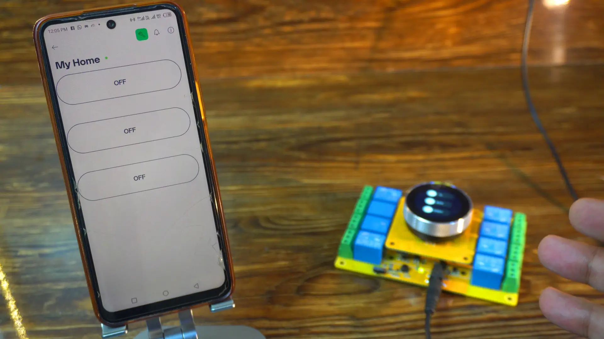
I haven’t connected real appliances to the board, because the onboard LEDs are more than enough to show what’s happening. Plus, you will also hear the clicking sound of the relays “if you watch video tutorial ;)”, so it’s very clear when they switch ON or OFF.
For the practical demonstration watch the video tutorial.
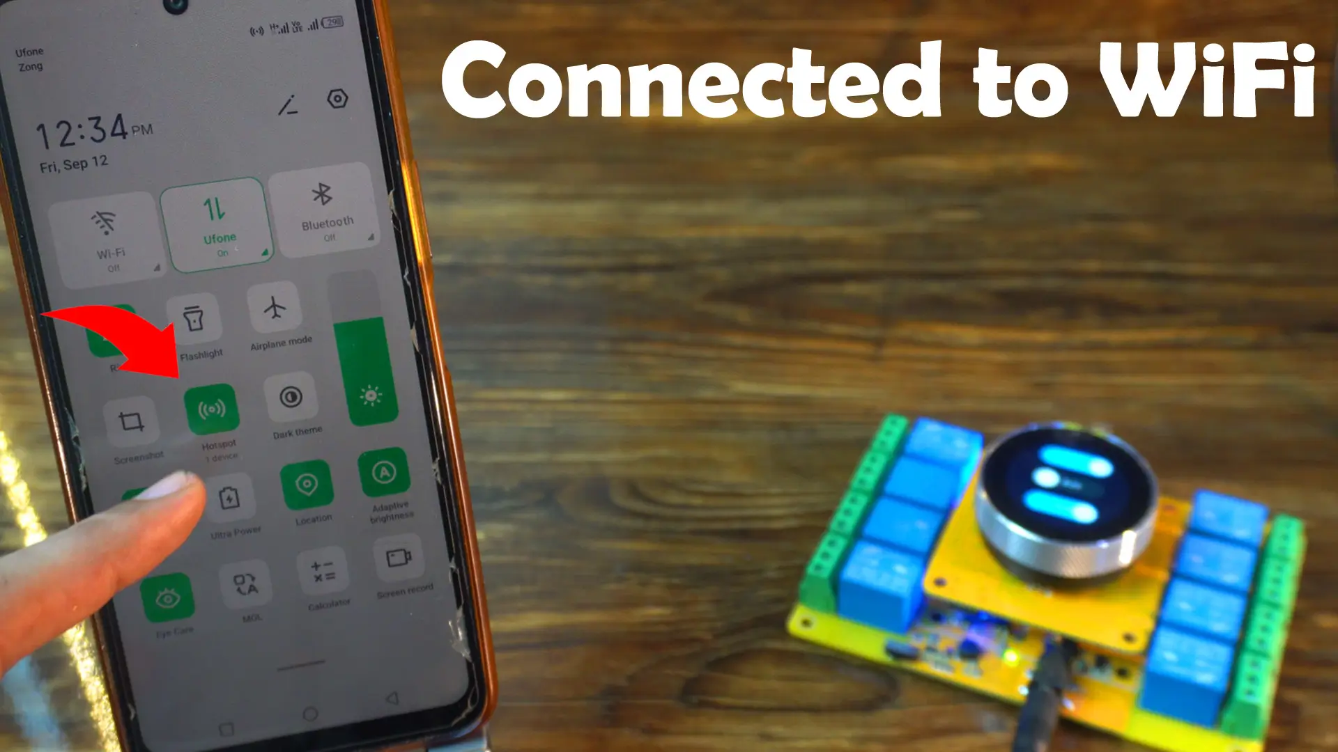
Right now, both my board and my mobile phone are connected to WiFi.
So, let’s first control the relays using the on-screen switches.
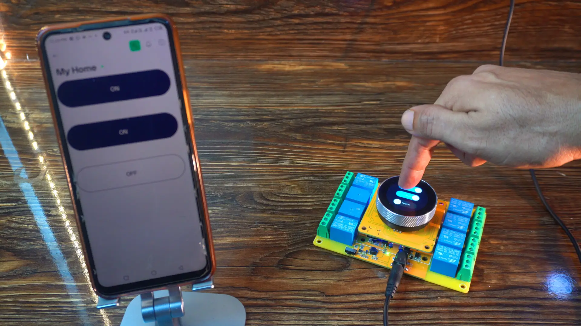
As you can see, it’s very fast and responsive. And you might have noticed; whenever I toggle a switch on the display, the same switch updates instantly in the Blynk app as well.
Now, let’s try the other way around; controlling the relays directly from the Blynk app.
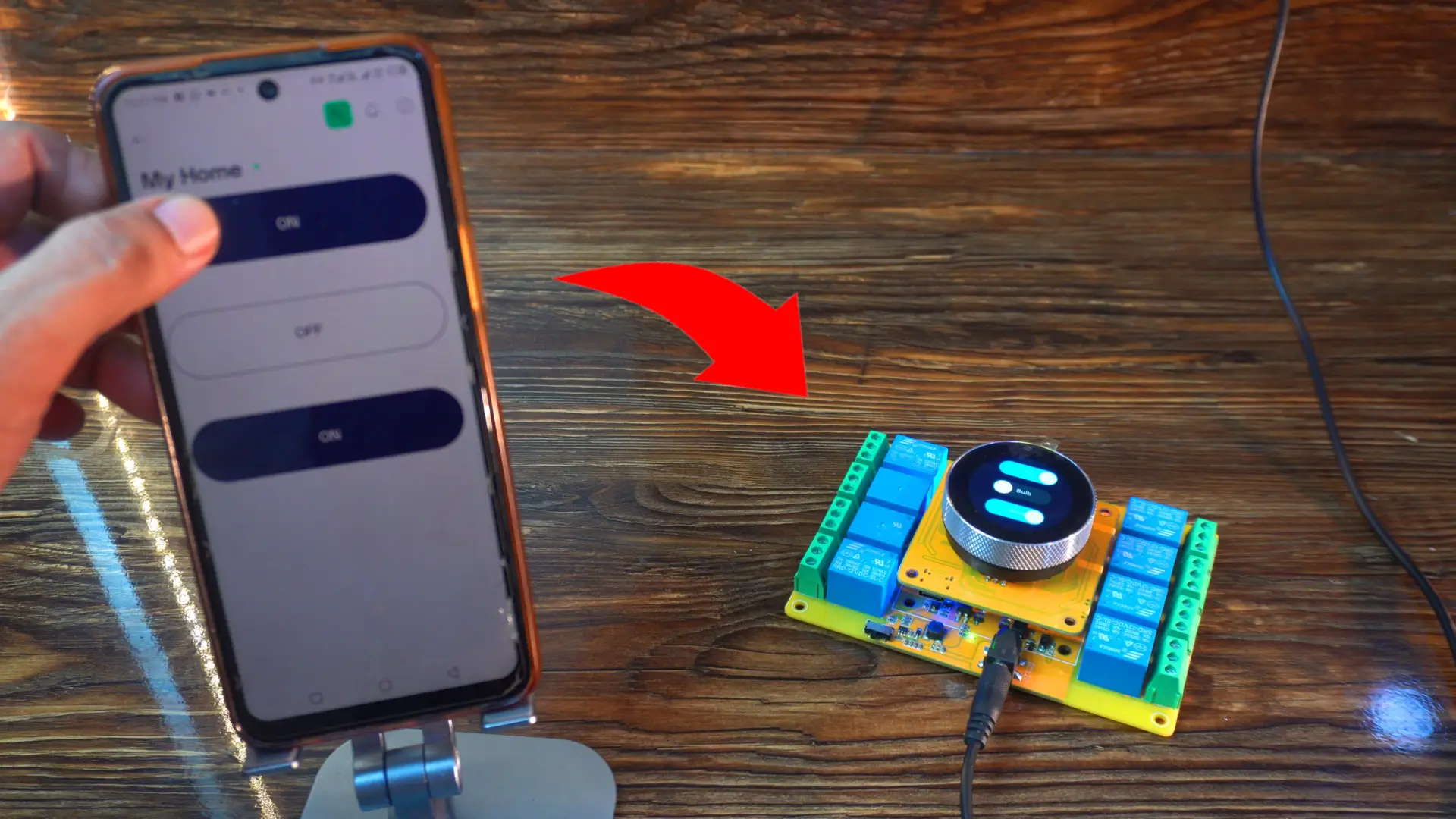
Again, you can see it’s super fast and responsive. Whenever I toggle a button here on the phone, the same button updates on the display UI in real-time.
But here’s the exciting part; what happens if I disconnect the WiFi?
Now the controller is no longer connected to WiFi…
And look; it’s still working perfectly!
Do you know why?
Because; we didn’t use Blynk.begin() in the code; because it blocks the program until a connection is made.
By handling WiFi and Blynk connections manually, the ESP32 remains responsive even if the internet drops or the Blynk server is unavailable.
Anyway, right now you can see that two switches are ON and one switch is OFF.
I am going to reconnect the controller to WiFi, and let’s see whether the Blynk app updates the status of these loads or not.
This might take a few seconds…
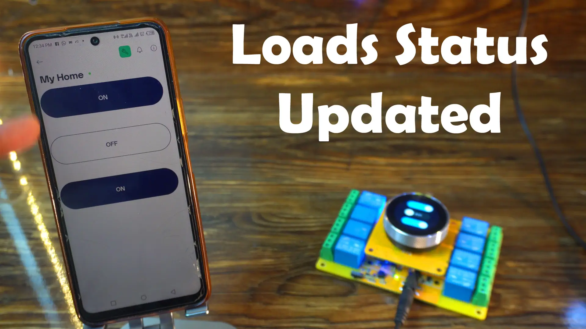
And there you go; amazing! The load status has automatically updated in the Blynk app.
Now I can also turn these same loads OFF directly from the Blynk app, and the changes will instantly show up on the display as well.
So with this system, you can control your appliances locally using the display or remotely from anywhere in the world using the Blynk app.
And in Version 3, we will take it even further; we will build a custom Android application with feedback acknowledgment, so you will always know the exact status of your appliances.
So, that’s all for now.
Watch Video Tutorial:

Discover more from Electronic Clinic
Subscribe to get the latest posts sent to your email.


