ESP32 ESP-NOW Wireless Servo & Relay Control Project
How to Build an ESP32 ESP-NOW Wireless Servo and Relay Controller (No WiFi Needed)
Last Updated on December 1, 2025 by Engr. Shahzada Fahad
Table of Contents
Description:
This is Version 6, and yes; this is the final article in our MaTouch 1.28-inch Toolset Timer Switch Relay Kit series.
Imagine controlling your devices wirelessly; not from your phone, not through a Wi-Fi router, and not via any IoT platform; but directly using the ESP32 ESP-NOW wireless control feature.
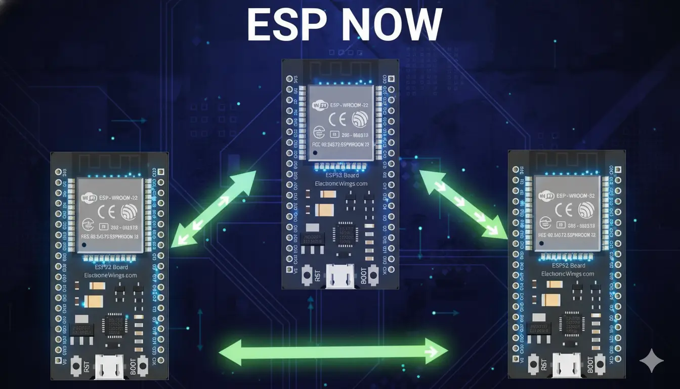
That’s right; today, we are using ESP-NOW, a power
ful communication protocol from Espressif that allows two or more ESP32 boards to send and receive data instantly without the need for an internet connection or access point.
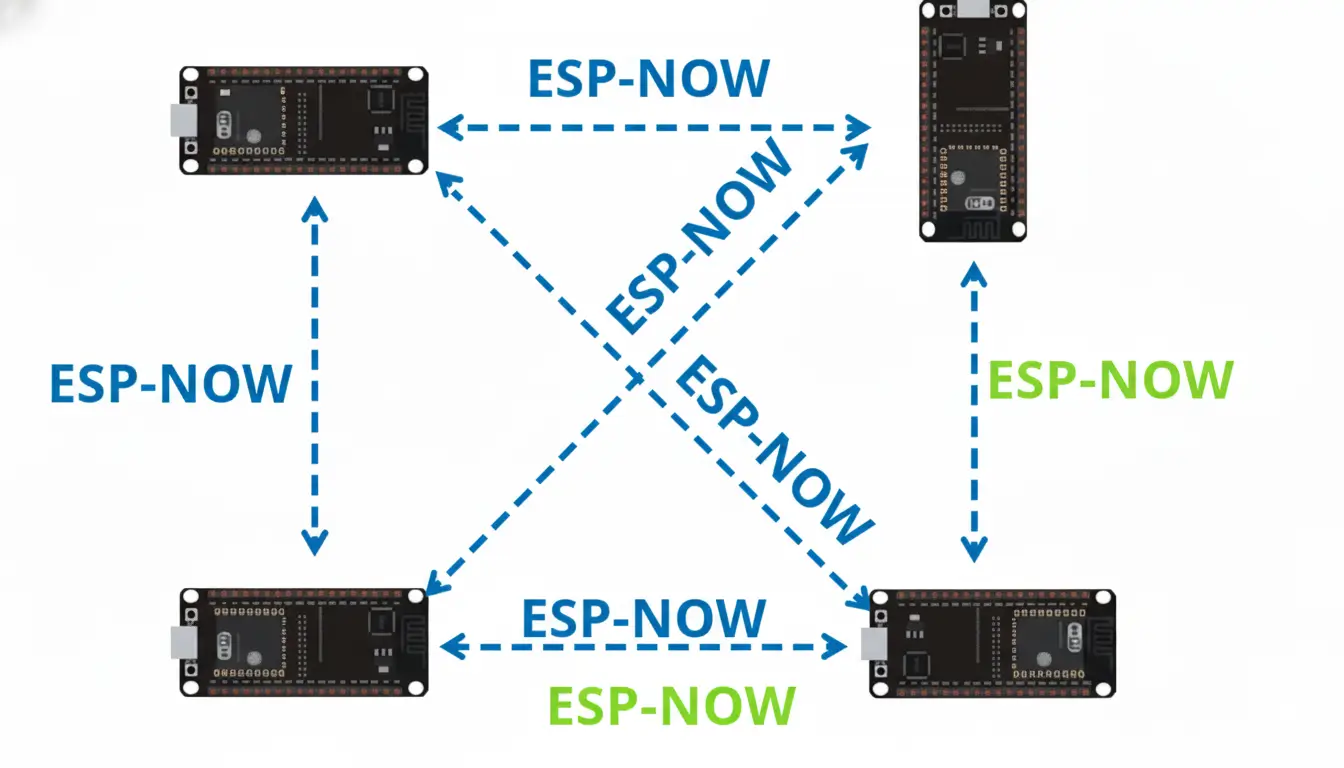
It’s fast, reliable, and perfect for projects like this; where you want real-time control and instant feedback between multiple devices.
I really love this kit because its top part is completely detachable; which means you can use it separately or integrate it into other projects.

If you have been following my previous articles, you will remember that in Version 1, I promised that one day we will make this upper part of the kit act as the transmitter and today, in Version 6, we are finally doing it.
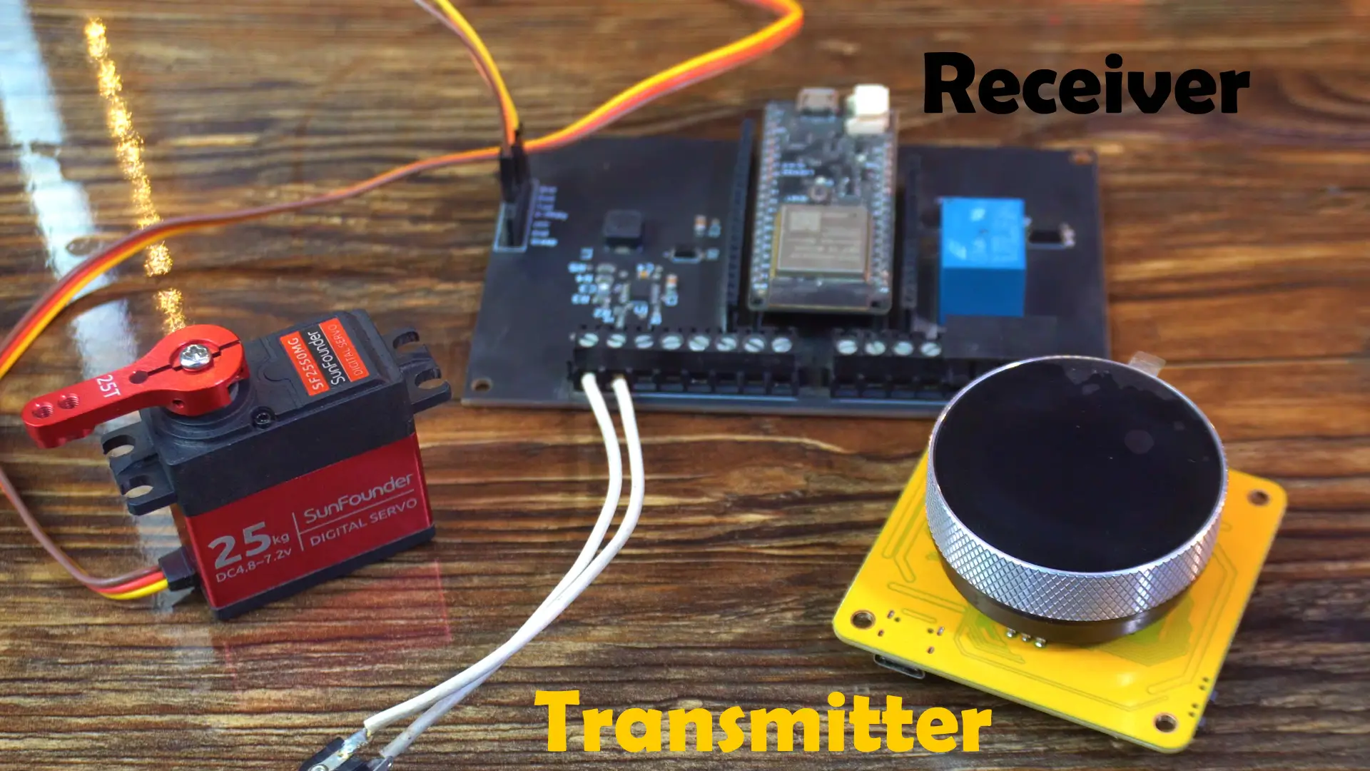
On the receiver side, I am using my custom ESP32 development board, which includes a relay connected to GPIO13. And the Servo is connected to GPIO4.
Together, they will create a complete wireless servo and relay control system; fully interactive and responsive.
Before the practical demonstration, let’s first take a look at the UI I created in SquareLine Studio.
UI Design in SquareLine Studio:

On Screen 1, we are displaying the date and time; I have used this same background image and labels in all my previous versions.
On Screen 2, we are showing the servo angle, which we will send to the receiver.
And on Screen 3, I have added a switch to control the relay on the receiver side.
Whenever I turn this switch ON or OFF, the “Relayfun” function is called.
I have only added three screens, but you can easily create more if you want.
I didn’t go into too much detail here because I have already explained all the basics of smartwatch programming in my dedicated series; so make sure to read those first for a better understanding.
Programming:
First, you need to download both codes; one for the transmitter side and one for the receiver side.
Transmitter Side Code:
|
1 2 3 4 5 6 7 8 9 10 11 12 13 14 15 16 17 18 19 20 21 22 23 24 25 26 27 28 29 30 31 32 33 34 35 36 37 38 39 40 41 42 43 44 45 46 47 48 49 50 51 52 53 54 55 56 57 58 59 60 61 62 63 64 65 66 67 68 69 70 71 72 73 74 75 76 77 78 79 80 81 82 83 84 85 86 87 88 89 90 91 92 93 94 95 96 97 98 99 100 101 102 103 104 105 106 107 108 109 110 111 112 113 114 115 116 117 118 119 120 121 122 123 124 125 126 127 128 129 130 131 132 133 134 135 136 137 138 139 140 141 142 143 144 145 146 147 148 149 150 151 152 153 154 155 156 157 158 159 160 161 162 163 164 165 166 167 168 169 170 171 172 173 174 175 176 177 178 179 180 181 182 183 184 185 186 187 188 189 190 191 192 193 194 195 196 197 198 199 200 201 202 203 204 205 206 207 208 209 210 211 212 213 214 215 216 217 218 219 220 221 222 223 224 225 226 227 228 229 230 231 232 233 234 235 236 237 238 239 240 241 242 243 244 245 246 247 248 249 250 251 252 253 254 255 256 257 258 259 260 261 262 263 264 265 266 267 268 269 270 271 272 273 |
#include <WiFi.h> #include <lvgl.h> #include <Arduino_GFX_Library.h> #include "ui.h" #include <RTClib.h> #include <ESP32Time.h> #include <esp_wifi.h> #include <esp_now.h> #include "touch.h" #include "pin_config.h" #include "local_store.h" /*Change to your screen resolution*/ static const uint16_t screenWidth = 240; static const uint16_t screenHeight = 240; static lv_disp_draw_buf_t draw_buf; static lv_color_t buf[screenWidth * screenHeight / 10]; Arduino_ESP32SPI *bus = new Arduino_ESP32SPI(TFT_DC, TFT_CS, TFT_SCLK, TFT_MOSI, TFT_MISO, HSPI, true); Arduino_GFX *gfx = new Arduino_GC9A01(bus, TFT_RES, 2 /* rotation */, true /* IPS */); RTC_PCF8563 rtc_pcf; ESP32Time rtc_esp; /* ================== NEW VARIABLES =================== */ volatile int counter = 90; // Default servo angle int State; int old_State; bool encoderActive = true; int lastButtonState = HIGH; uint8_t receiverMac[] = {0x08, 0xD1, 0xF9, 0xEC, 0x6D, 0x48}; //Replace with your receiver’s MAC typedef struct struct_message { int angle; int relayState; // 🔹 NEW: relay on/off } struct_message; struct_message sendData; void IRAM_ATTR encoder_irq(); /* ================== ESP-NOW =================== */ void OnDataSent(const uint8_t *mac_addr, esp_now_send_status_t status) { Serial.print("Last Packet Send Status: "); Serial.println(status == ESP_NOW_SEND_SUCCESS ? "Delivery Success" : "Delivery Fail"); } long lastCounter = 0; unsigned long lastSend = 0; const unsigned long sendInterval = 20; // send every 20ms if changed /* ================== SETUP =================== */ void setup() { Serial.begin(115200); delay(1000); pin_init(); Wire.begin(TOUCH_SDA, TOUCH_SCL); rtc_pcf_init(); rtc_reset(); gfx->begin(); delay(200); lv_init(); lv_disp_draw_buf_init(&draw_buf, buf, NULL, screenWidth * screenHeight / 10); static lv_disp_drv_t disp_drv; lv_disp_drv_init(&disp_drv); disp_drv.hor_res = screenWidth; disp_drv.ver_res = screenHeight; disp_drv.flush_cb = my_disp_flush; disp_drv.draw_buf = &draw_buf; lv_disp_drv_register(&disp_drv); static lv_indev_drv_t indev_drv; lv_indev_drv_init(&indev_drv); indev_drv.type = LV_INDEV_TYPE_POINTER; indev_drv.read_cb = my_touchpad_read; lv_indev_drv_register(&indev_drv); ui_init(); Serial.println("Setup done"); xTaskCreatePinnedToCore(Task_TFT, "Task_TFT", 10240, NULL, 2, NULL, 0); // ESP-NOW initialization WiFi.mode(WIFI_STA); esp_wifi_set_channel(1, WIFI_SECOND_CHAN_NONE); // make sure both use same channel Serial.println("Transmitter MAC: " + WiFi.macAddress()); if (esp_now_init() != ESP_OK) { Serial.println("ESP-NOW init failed!"); return; } esp_now_peer_info_t peerInfo; memset(&peerInfo, 0, sizeof(peerInfo)); memcpy(peerInfo.peer_addr, receiverMac, 6); peerInfo.channel = 1; // must match the line above peerInfo.encrypt = false; if (esp_now_add_peer(&peerInfo) != ESP_OK) { Serial.println("❌ Failed to add peer. Check MAC & Wi-Fi mode."); } else { Serial.println("✅ Peer added successfully."); } esp_now_register_send_cb(OnDataSent); esp_now_register_recv_cb(OnDataRecv); //Add this line here // LVGL timers lv_timer_create(update_datetime, 1000, NULL); // every 1 sec lv_timer_create(update_encoder, 200, NULL); // every 200 ms } /* ================== LOOP =================== */ void loop() { lv_timer_handler(); delay(5); } /* ================== DISPLAY + TOUCH =================== */ void Task_TFT(void *pvParameters) { while (1) { lv_timer_handler(); vTaskDelay(50); } } void my_disp_flush(lv_disp_drv_t *disp, const lv_area_t *area, lv_color_t *color_p) { uint32_t w = (area->x2 - area->x1 + 1); uint32_t h = (area->y2 - area->y1 + 1); #if (LV_COLOR_16_SWAP != 0) gfx->draw16bitBeRGBBitmap(area->x1, area->y1, (uint16_t *)&color_p->full, w, h); #else gfx->draw16bitRGBBitmap(area->x1, area->y1, (uint16_t *)&color_p->full, w, h); #endif lv_disp_flush_ready(disp); } void my_touchpad_read(lv_indev_drv_t *indev_driver, lv_indev_data_t *data) { int touchX = 0, touchY = 0; if (read_touch(&touchX, &touchY) == 1) { data->state = LV_INDEV_STATE_PR; data->point.x = (uint16_t)(240 - touchX); data->point.y = (uint16_t)(240 - touchY); } else { data->state = LV_INDEV_STATE_REL; } } /* ================== PIN INIT =================== */ void pin_init() { pinMode(TFT_BLK, OUTPUT); digitalWrite(TFT_BLK, HIGH); pinMode(BUTTON_PIN, INPUT_PULLUP); pinMode(ENCODER_CLK, INPUT_PULLUP); pinMode(ENCODER_DT, INPUT_PULLUP); old_State = digitalRead(ENCODER_CLK); attachInterrupt(ENCODER_CLK, encoder_irq, CHANGE); } /* ================== ENCODER =================== */ void IRAM_ATTR encoder_irq() { State = digitalRead(ENCODER_CLK); if (State != old_State) { if (digitalRead(ENCODER_DT) == State) counter++; else counter--; if (counter < 0) counter = 0; if (counter > 180) counter = 180; } old_State = State; } /* ================== RTC =================== */ void rtc_pcf_init() { if (!rtc_pcf.begin()) { Serial.println("Couldn't find RTC"); while (1) delay(10); } if (rtc_pcf.lostPower()) { Serial.println("PCF8563 not initialized"); } rtc_pcf.start(); } void rtc_reset() { rtc_pcf.adjust(DateTime(2025, 10, 8, 15, 30, 0)); DateTime now = rtc_pcf.now(); rtc_esp.setTime(now.second(), now.minute(), now.hour(), now.day(), now.month(), now.year()); } /* ================== UI UPDATERS =================== */ void update_datetime(lv_timer_t * timer) { DateTime now = rtc_pcf.now(); char bufTime[16]; sprintf(bufTime, "%02d:%02d:%02d", now.hour(), now.minute(), now.second()); lv_label_set_text(ui_lbltime, bufTime); char bufDate[16]; sprintf(bufDate, "%02d/%02d/%04d", now.day(), now.month(), now.year()); lv_label_set_text(ui_lbldate, bufDate); } void update_encoder(lv_timer_t * timer) { int buttonState = digitalRead(BUTTON_PIN); if (lastButtonState == HIGH && buttonState == LOW) { encoderActive = !encoderActive; Serial.println(encoderActive ? "Encoder ACTIVATED" : "Encoder DEACTIVATED"); delay(300); } lastButtonState = buttonState; static long lastCounter = 0; static unsigned long lastSend = 0; const unsigned long sendInterval = 20; // send every 20ms if changed // Only send when active if (encoderActive) { int newCounter = counter; if (newCounter != lastCounter && millis() - lastSend > sendInterval) { sendData.angle = newCounter; esp_now_send(receiverMac, (uint8_t *)&sendData, sizeof(sendData)); Serial.printf("Sent Angle: %d°\n", newCounter); lastCounter = newCounter; lastSend = millis(); } } // Update display char buf[16]; sprintf(buf, "Angle: %d°", counter); lv_label_set_text(ui_lblencodervalue, buf); } void Relayfun(lv_event_t * e) { bool state = lv_obj_has_state(ui_Swrelay, LV_STATE_CHECKED); //check switch state sendData.relayState = state ? 1 : 0; esp_now_send(receiverMac, (uint8_t *)&sendData, sizeof(sendData)); Serial.printf("Relay command sent: %s\n", state ? "ON" : "OFF"); } void OnDataRecv(const uint8_t * mac, const uint8_t *incomingData, int len) { struct_message feedback; memcpy(&feedback, incomingData, sizeof(feedback)); Serial.print("Feedback received → Relay: "); Serial.println(feedback.relayState ? "ON" : "OFF"); //Safely update LVGL label lv_label_set_text_fmt(ui_Label1, "Relay: %s", feedback.relayState ? "ON" : "OFF"); lv_obj_invalidate(ui_Label1); // force redraw lv_timer_handler(); // process update } |
Receiver Side Code:
|
1 2 3 4 5 6 7 8 9 10 11 12 13 14 15 16 17 18 19 20 21 22 23 24 25 26 27 28 29 30 31 32 33 34 35 36 37 38 39 40 41 42 43 44 45 46 47 48 49 50 51 52 53 54 55 56 57 58 59 60 61 62 63 64 65 66 67 68 69 70 71 72 73 74 75 76 77 |
#include <WiFi.h> #include <esp_now.h> #include <ESP32Servo.h> #define SERVO_PIN 4 #define RELAY_PIN 13 //feedback pin Servo myServo; typedef struct struct_message { int angle; bool relayState; } struct_message; struct_message incomingData; struct_message feedbackData; //to send back int currentAngle = 90; int targetAngle = 90; unsigned long lastMoveTime = 0; const int moveInterval = 15; uint8_t transmitterMac[] = {0x08, 0xD1, 0xF9, 0xAA, 0xBB, 0xCC}; // Replace with your transmitter MAC void OnDataRecv(const uint8_t * mac, const uint8_t *incomingDataBytes, int len) { memcpy(&incomingData, incomingDataBytes, sizeof(incomingData)); // Servo control if (abs(incomingData.angle - targetAngle) > 1) { targetAngle = incomingData.angle; Serial.printf("Received target angle: %d°\n", targetAngle); } // Relay control digitalWrite(RELAY_PIN, incomingData.relayState ? HIGH : LOW); // Prepare feedback feedbackData.angle = targetAngle; feedbackData.relayState = digitalRead(RELAY_PIN); esp_now_send(transmitterMac, (uint8_t *)&feedbackData, sizeof(feedbackData)); } void setup() { Serial.begin(115200); myServo.attach(SERVO_PIN); pinMode(RELAY_PIN, OUTPUT); myServo.write(currentAngle); WiFi.mode(WIFI_STA); Serial.println("Receiver MAC: " + WiFi.macAddress()); if (esp_now_init() != ESP_OK) { Serial.println("ESP-NOW init failed!"); return; } // Add peer esp_now_peer_info_t peerInfo; memcpy(peerInfo.peer_addr, transmitterMac, 6); peerInfo.channel = 1; peerInfo.encrypt = false; esp_now_add_peer(&peerInfo); esp_now_register_recv_cb(OnDataRecv); Serial.println("Receiver ready."); } void loop() { unsigned long now = millis(); if (now - lastMoveTime >= moveInterval) { lastMoveTime = now; if (currentAngle < targetAngle) currentAngle++; else if (currentAngle > targetAngle) currentAngle--; myServo.write(currentAngle); } } |
Start by uploading the receiver code.
Once it’s uploaded, open the Serial Monitor and copy the MAC address shown there.
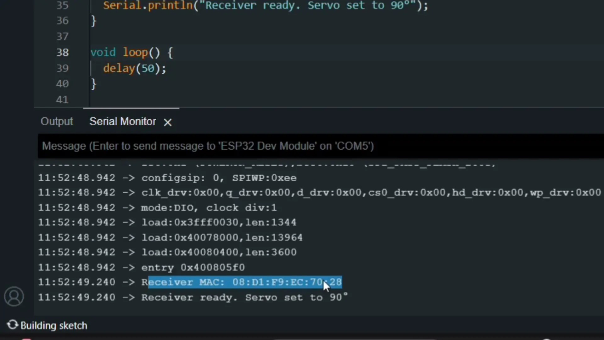
Then, paste this MAC address into the transmitter code,
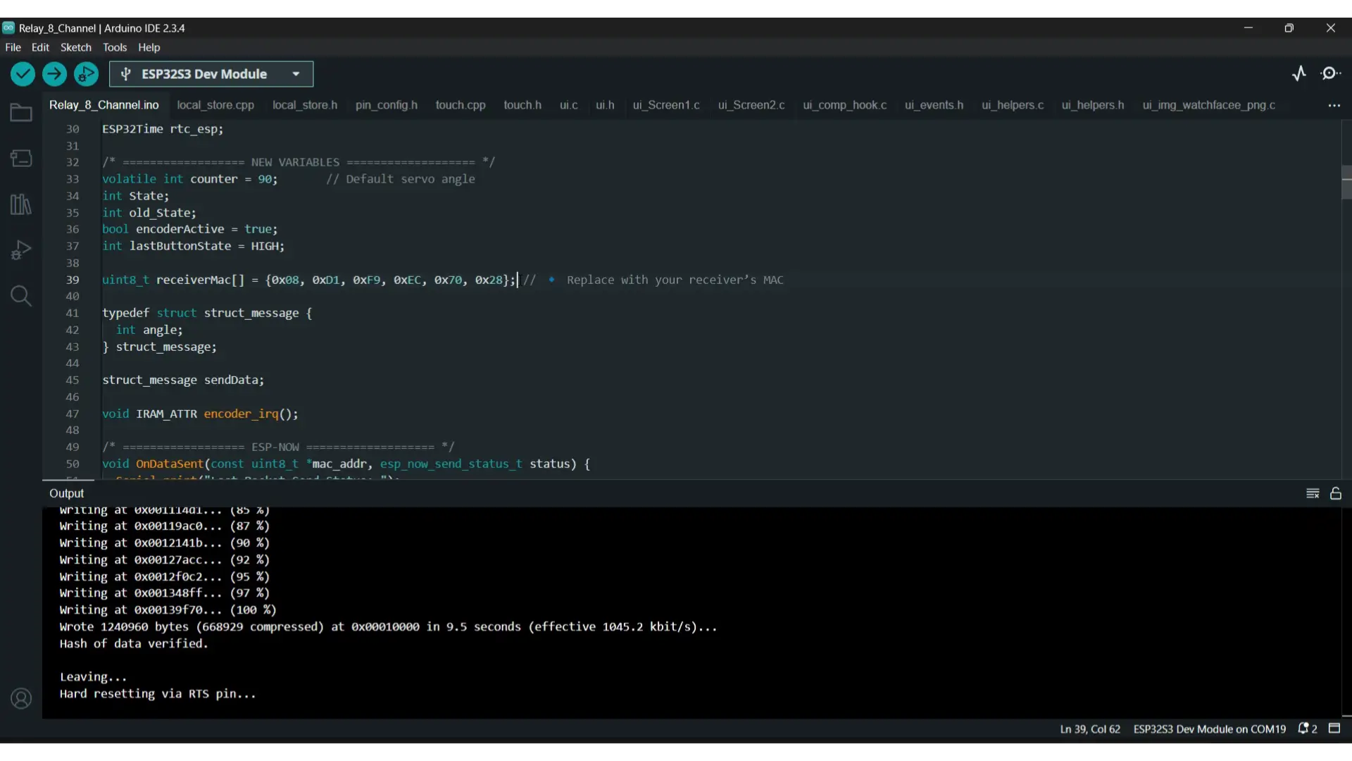
and finally, upload the transmitter code.
I have already explained in detail how to upload the code and which library versions to use in the earlier videos and articles of this series, so make sure to watch or read those first if you haven’t already.
Practical Demonstration:
Both the transmitter and receiver sides are completely ready; so let’s go ahead and power them up.
The transmitter first sends the servo angle wirelessly; but only when the encoder is active.
Right now, you can see I am rotating the encoder, but nothing is happening. That’s because the encoder is deactivated.
To activate it, we simply press the built-in pushbutton.
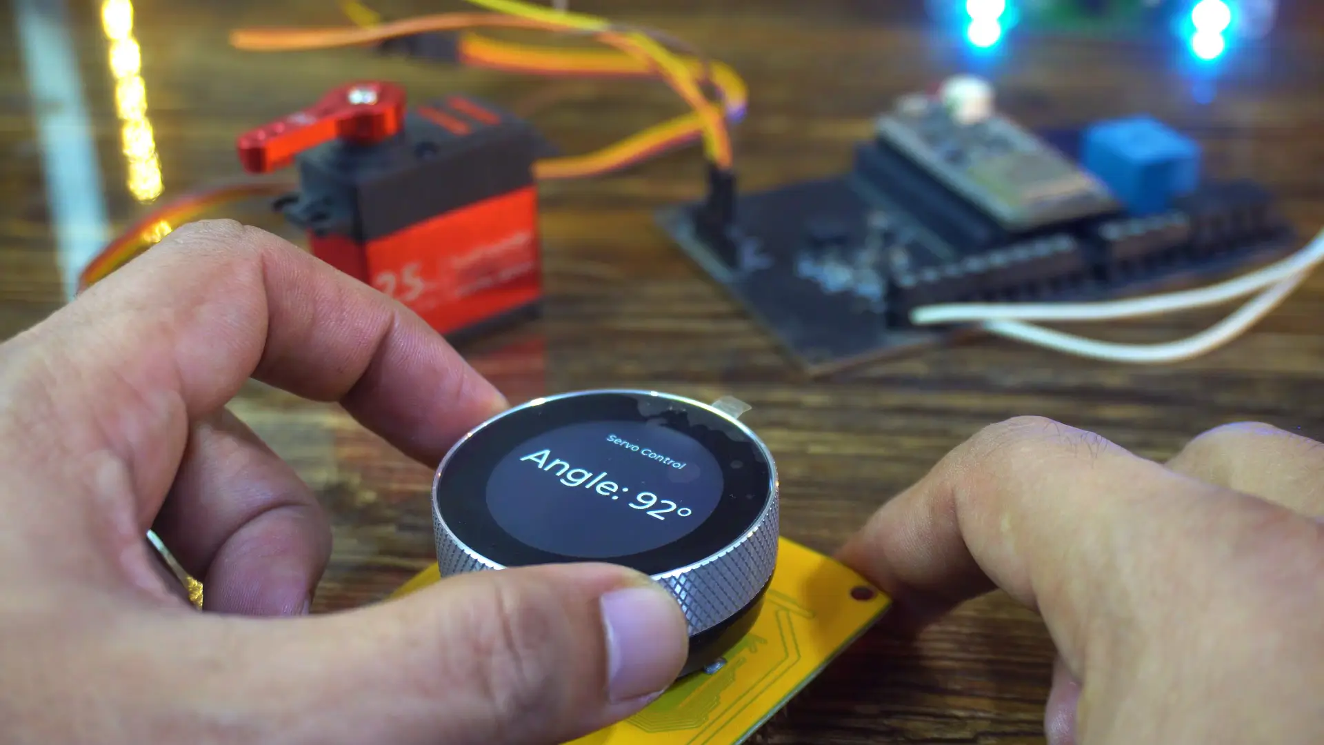
Once active, every small rotation updates the servo position on the receiver instantly — smooth, precise, and completely lag-free.
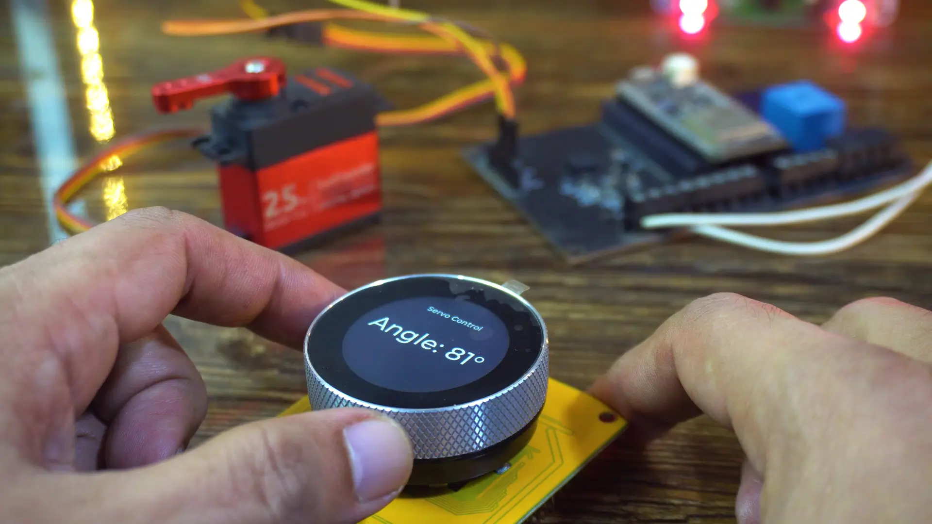
When the encoder is deactivated, it doesn’t control the servo in real-time, but you can still use it to set the desired angle. Then, as soon as you press the button, the servo position updates immediately.
If I swipe my finger to the right, you will see screen3; where I have added a switch to control the relay on the receiver side.

The moment I toggle the switch, the relay responds instantly.

It’s incredibly fast!
And you know why?
Because there’s no Wi-Fi setup, no pairing, no cloud delay; just instant, direct communication using ESP-NOW.
ESP32 ESP-NOW Performance:
Now we are going to perform a range test to see how far we can control the servo and relay wirelessly. Watch the video tutorial.
My brother was standing about 20 meters away, and it still worked perfectly.
And then he even moved farther away and as you can see, he is quite far now; but he can still control the relay from that distance without any issues.

If you want the complete project; including the SquareLine Studio project, UI files, and all source codes; they are available on my Patreon page.
So, that’s all for now.
Watch Video Tutorial:

Discover more from Electronic Clinic
Subscribe to get the latest posts sent to your email.


