ESP32 + HMMD mmWave Sensor: Real Tests + Blynk IoT!
Last Updated on August 16, 2025 by Engr. Shahzada Fahad
Table of Contents
Description:
ESP32 + HMMD mmWave Sensor: Real Tests + Blynk IoT – Waveshare’s HMMD mmWave Sensor is going to amaze you all. So, if you are thinking of purchasing an mmWave sensor right now, wait a bit. You need to decide after reading this article whether you should get the HMMD mmWave Sensor or some other mmWave Radar module.

And I am surprised why no one has written an article on this mmWave sensor yet. Maybe they were intimidated by the communication protocol formats, wondering how to send commands and how to fetch and use data from the frames. It’s something which I have already done in my previous article on the RD-03D mmWave sensor, for which I wrote the code completely from scratch. So, I know how to use all this information, and of course, I am going to share all that information with you guys too.
And that’s not all.
We will also practically use the HMMD mmWave sensor to control a light, and I will also explain how you can define your own custom detection range.
Additionally, we will use this mmWave Sensor with the Blynk application. You probably already know about Blynk; with its help, you will be able to monitor this mmWave Sensor from anywhere in the world.
To check how powerful and reliable this sensor is, I will also perform different tests on it, such as:
- Can it detect through cardboard boxes?
- Hardboard penetration test.
- Can this mmWave sensor see through Fabric? I call it the Ghost mode. We will see if it is powerful enough to detect me from behind the curtains.
- I am also going to test it under a running ceiling fan.
- We will also check if it can detect human presence behind Glass, Wood, and a Wall.
So, without any further delay let’s get started!!!
Amazon Links:
ESP32 WiFi + Bluetooth Module (Recommended)
Other Tools and Components:
Arduino Nano USB C type (Recommended)
*Please Note: These are affiliate links. I may make a commission if you buy the components through these links. I would appreciate your support in this way!
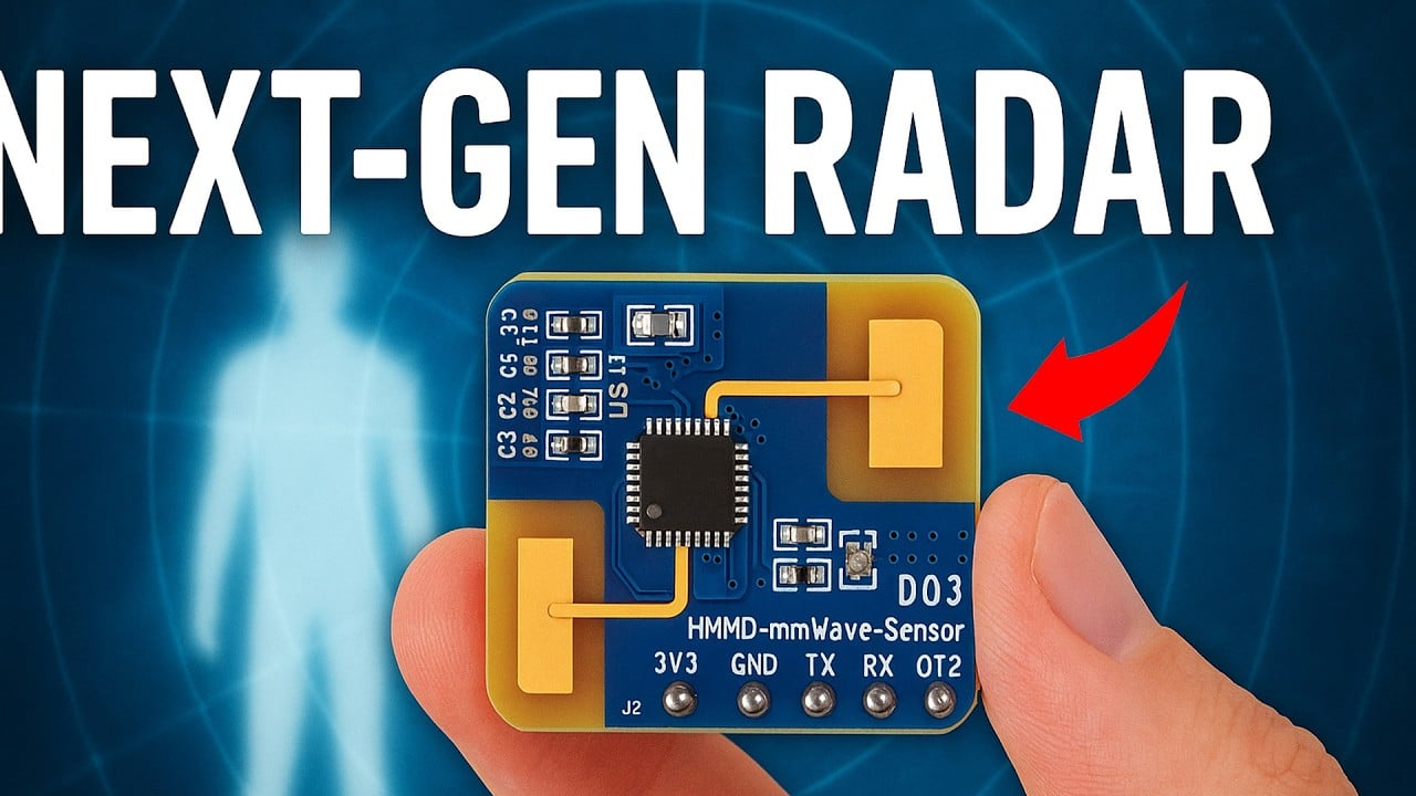
About the HMMD mmWave Sensor:
The HMMD mmWave Sensor is an advanced human micro-motion detection device capable of identifying moving, standing, and even stationary human presence with remarkable precision. Designed for versatility, its performance varies based on how it’s installed:
When wall-mounted, it can detect moving human targets up to 10 meters away and micro-movements up to 6 meters;

When ceiling-mounted, it offers detection ranges of 5 meters for motion and 4 meters for micro-motion.

With a detection accuracy of just 0.15 meters for moving targets within a 10-meter line of sight, the HMMD sensor delivers reliable and highly sensitive performance, making it ideal for applications requiring discreet and continuous human presence monitoring.

- Detection Range (wall-mount): Motion human body target 10m; Micro-motion human body target 6m
- Detection Range (ceiling-mount): Motion human body target 5m; Micro-motion human body target 4m
- Detection Accuracy: 0.15m (for moving targets within 10m straight-line distance from the radar)
It Comes with the Silicon Micro AIoT Millimeter-Wave Sensor SoC S3KM1110. And
Onboard high-performance 24GHz one-transmit-one-receive antenna and peripheral circuits.
It supports UART communication protocol and GPIO output, facilitating easy integration with host boards such as Raspberry Pi, Arduino, ESP32, and Jetson Nano.
HMMD mmWave Sensor Pinout:

Pin 1 is the 3.3V power input, and the module works with a supply voltage between 3.0 to 3.6 volts; 3.3V is typical.
Pin 2 is GND.
Then we have TX and RX for UART communication.
Finally, Pin 5 is the OT2 or GPIO output pin, which goes high when human presence is detected, and low when no presence is detected; perfect for triggering relays, LEDs, or microcontrollers.

HMMD mmWave Sensor wiring:

Connect its 3.3V and GND pins to the ESP32 3.3V and GND. And connect the TX and RX pins to the GPIO 16 and 17 on the ESP32. For the initial testing, this much wiring is enough. But as I mentioned earlier, we will also control a light, so for that we will use this 5V SPDT type relay. It is connected to GPIO13. You can follow this circuit diagram for the relay connections.
Relay Driver Circuit Diagram:

After this, you need to go to the HMMD mmWave Sensor’s wiki page. In the Hardware Test section, follow the steps to connect the sensor to your PC using a USB to TTL converter. This allows you not only to change the sensor’s parameters but also to set custom values. I have used this sensor before, so I would suggest that you should not change the default settings unless you know exactly what you are doing.
Anyway, go to the communication protocol section, and then under the Protocol Format, you will see that the HMMD mmWave Sensor data communication uses the small end format, and all data is in hexadecimal.
You absolutely don’t need to get confused by seeing all that stuff. Just read it so you get an idea of how to send the command and what the module’s acknowledgment will be like.
If you need the Radar firmware version; you can send this command to the mmWave sensor
Sending data:
| FH(frame header) Byte 1~4 | In-frame Data Length Byte 5,6 | In-frame Data Byte 7,8 | Frame Tail Byte 9~12 |
| FD FC FB FA | 02 00 | 00 00 | 04 03 02 01 |
And then the module will reply with an acknowledgement.
Module ACK: (Successful Example)
| Byte 1~4 | Byte 5,6 | Byte 7,8 | Byte 9,10 | Byte 11,12 | Byte 13~18 | Byte 19~24 |
| FD FC FB FA | 0C 00 | 00 01 | 00 00 | 06 00 | 76 31 2E 35 2E 35 | 04 03 02 01 |
Similarly; you can read the serial number of the mmWave Radar, you can read registers, and configuration parameters.
You often don’t see all these things because, for most sensors, programmers have written libraries. But in the case of the HMMD mmWave sensor, we don’t have any library. So, that’s why we have to manually send the command ourselves and then extract the useful data from the module’s acknowledgment frame. Which is very easy.
Normal Mode
| Byte 1~4 | Byte5,6 | Byte 7,8 | Byte9~10 | Byte 11~14 | Byte 15~18 |
| FD FC FB FA | 08 00 | 12 00 | 00 00 | 64 00 00 00 | 04 03 02 01 |
We just need to send this command to the module, and then in the acknowledgment, the module will give us a reply like this, which consists of the Detection Result, Target Distance, and the energy values for each distance gate.
| Frame Header | Length | Detection Result | Target Distance | The energy values for each distance gate | Frame Tail |
| F4 F3 F2 F1 | 2 bytes, total number of bytes for detection result, target distance, and energy values for each distance gate | 1 byte, 00 absent, 01 present | 2 bytes indicating the distance of the target phase from the radar in the scene | 32 bytes, 16 (total number of distance gates) * 2 bytes, size of energy value for each distance gate from 0 to 15 | F8 F7 F6 F |
To get started! Simply scroll down to the Resource section and download the Demo Code. Inside this folder you will find codes for the Arduino_ESP32, Jetson_nano, Raspberry Pi, RP2040, and windows. Since I am using ESP32 and the Arduino IDE, So I started with the Arduino_ESP32 code.
Unfortunately, this code didn’t work for me, so I wrote this basic program myself.
Reading Frames:
|
1 2 3 4 5 6 7 8 9 10 11 12 13 14 15 16 17 18 19 20 21 22 23 24 25 26 27 28 29 30 31 32 33 34 35 36 37 38 39 40 41 42 43 44 45 46 47 48 49 50 51 52 53 54 55 56 57 58 59 60 61 62 63 64 65 66 67 68 69 70 71 72 73 74 75 76 77 78 79 80 81 82 83 84 85 86 87 88 89 90 91 92 93 |
// Define the pins for our secondary hardware serial port (Serial2) // RX2 pin is GPIO16, TX2 pin is GPIO17 #define RX2_PIN 16 #define TX2_PIN 17 void setup() { // Start the primary serial communication (USB Monitor) with a baud rate of 115200 Serial.begin(115200); // Wait for the serial port to initialize (optional, but good practice) // Added a timeout just in case Serial never becomes available unsigned long startAttemptTime = millis(); while (!Serial && millis() - startAttemptTime < 2000) { // Wait max 2 seconds delay(100); } Serial.println("Serial Monitor Initialized."); // Start the secondary hardware serial port (Serial2) // Format: SerialX.begin(baudrate, config, rxPin, txPin); // SERIAL_8N1 means 8 data bits, No parity, 1 stop bit (common default) Serial2.begin(115200, SERIAL_8N1, RX2_PIN, TX2_PIN); Serial.println("Serial2 Initialized on RX:" + String(RX2_PIN) + ", TX:" + String(TX2_PIN)); // Hex string to send String hex_to_send = "FDFCFBFA0800120000006400000004030201"; Serial.println("Sending Hex Data over Serial2..."); sendHexData(hex_to_send); Serial.println("Hex Data Sent."); } void loop() { // Read and print serial data received on Serial2 to the Serial Monitor readSerialData(); // Add a small delay to prevent the loop from consuming 100% CPU // if there's no data frequently arriving. Adjust as needed. delay(10); } void sendHexData(String hexString) { int hexStringLength = hexString.length(); // Ensure the hex string has an even number of characters if (hexStringLength % 2 != 0) { Serial.println("Error: Hex string must have an even number of characters."); return; } int byteCount = hexStringLength / 2; // Create a byte array dynamically or use std::vector for safer memory management if needed // Using Variable Length Array (VLA) here, which is a C99/GCC extension byte hexBytes[byteCount]; for (int i = 0; i < hexStringLength; i += 2) { // Extract two characters (one byte in hex representation) String byteString = hexString.substring(i, i + 2); // Convert the hex string byte to an actual byte byte hexByte = (byte)strtoul(byteString.c_str(), NULL, 16); hexBytes[i / 2] = hexByte; } // Send bytes through the hardware serial port (Serial2) Serial.print("Sending "); Serial.print(byteCount); Serial.print(" bytes: "); for(int i=0; i<byteCount; i++) { if (hexBytes[i] < 16) Serial.print("0"); // Pad with zero if needed Serial.print(hexBytes[i], HEX); Serial.print(" "); } Serial.println(); Serial2.write(hexBytes, byteCount); } void readSerialData() { // Check if data is available on Serial2 if (Serial2.available() > 0) { Serial.print("Data received on Serial2: "); // Read all available bytes while (Serial2.available() > 0) { byte incomingByte = Serial2.read(); // Read as byte // Option 1: Print as raw character (might be unreadable for binary data) // Serial.print((char)incomingByte); // Option 2: Print as HEX value (often better for debugging binary/hex) if (incomingByte < 16) Serial.print("0"); // Pad with leading zero if needed Serial.print(incomingByte, HEX); Serial.print(" "); // Add space between hex values } Serial.println(); // Add a newline after printing all received bytes } } |

As you can see, when I move around in front of the sensor, some numbers change

Which tells us the sensor is working! Now, what you are seeing on the screen is the raw data, in hexadecimal.
This raw data is usually where people get stuck, because they don’t know how to pull the actual distance reading out of it. Even the product’s wiki page doesn’t go much further than showing this raw data.
Anyway, figuring out how to read that data was the hard part, and I have already done that. The structure of the data frame is now crystal clear.
I have slightly modified the same code to print the actual distance in centimeters.
HMMD mmWave Sensor Actual Distance in cm:
|
1 2 3 4 5 6 7 8 9 10 11 12 13 14 15 16 17 18 19 20 21 22 23 24 25 26 27 28 29 30 31 32 33 34 35 36 37 38 39 40 41 42 43 44 45 46 47 48 49 50 51 52 53 54 55 56 57 58 59 60 61 62 63 64 65 66 67 68 69 70 71 72 73 74 75 76 77 78 79 80 81 82 83 84 85 86 87 88 89 90 91 |
// Define the pins for our secondary hardware serial port (Serial2) #define RX2_PIN 16 #define TX2_PIN 17 void setup() { // Start the primary serial communication (USB Monitor) Serial.begin(115200); unsigned long startAttemptTime = millis(); while (!Serial && millis() - startAttemptTime < 2000) { delay(100); } Serial.println("Serial Monitor Initialized."); // Start Serial2 for the HMMD Sensor Serial2.begin(115200, SERIAL_8N1, RX2_PIN, TX2_PIN); Serial.println("Serial2 Initialized on RX:" + String(RX2_PIN) + ", TX:" + String(TX2_PIN)); // Keep the command sending for now, as you confirmed the current code works. // It might be putting the sensor into the correct output mode or keeping it active. String hex_to_send = "FDFCFBFA0800120000006400000004030201"; // Normal Mode command? Serial.println("Sending initial command over Serial2..."); sendHexData(hex_to_send); Serial.println("Initial command sent."); Serial.println("Waiting for sensor readings..."); } void loop() { // Read and process lines from Serial2 readAndProcessSensorLines(); // Small delay is fine delay(10); } // Original function to send command bytes - KEEPING AS IS void sendHexData(String hexString) { int hexStringLength = hexString.length(); if (hexStringLength % 2 != 0) { Serial.println("Error: Hex string must have an even number of characters."); return; } int byteCount = hexStringLength / 2; byte hexBytes[byteCount]; for (int i = 0; i < hexStringLength; i += 2) { String byteString = hexString.substring(i, i + 2); byte hexByte = (byte)strtoul(byteString.c_str(), NULL, 16); hexBytes[i / 2] = hexByte; } // Print confirmation of what's being sent Serial.print("Sending "); Serial.print(byteCount); Serial.print(" bytes: "); for(int i=0; i<byteCount; i++) { if (hexBytes[i] < 16) Serial.print("0"); Serial.print(hexBytes[i], HEX); Serial.print(" "); } Serial.println(); // Send the data Serial2.write(hexBytes, byteCount); } // *** MODIFIED FUNCTION TO READ AND PARSE LINES *** void readAndProcessSensorLines() { // Check if data is available on Serial2 while (Serial2.available() > 0) { // Read a line of text until a newline character (\n) is received // The timeout helps prevent blocking forever if a line ending is missed String line = Serial2.readStringUntil('\n'); // Clean up the line: remove potential carriage return (\r) and leading/trailing whitespace line.trim(); // Check if the line contains the "Range" information if (line.startsWith("Range ")) { // Extract the substring after "Range " String distanceStr = line.substring(6); // Start extracting after "Range " (index 6) // Convert the distance string to an integer int distance = distanceStr.toInt(); // Print the extracted distance Serial.print("Detected Distance: "); Serial.print(distance); Serial.println(" cm"); // Assuming the unit is cm, adjust if needed } } } |
Our mmWave Sensor is now completely ready.

Look how responsive it is, and its distance accuracy is absolutely mind-blowing!
Next, we will use the HMMD mmWave sensor with the Blynk application. With Blynk, we can monitor this Radar module from anywhere in the world. This is the same blynk application I created for the C4001 mmWave sensor I am using the same virtual pin V0.

The only change I made is that, I renamed it to HMMD mmWave and that’s it.
You can see in the ESP32 code given below, I am using the same Template name, ID, and authorization token.
HMMD mmWave Sensor and Blynk IoT:
|
1 2 3 4 5 6 7 8 9 10 11 12 13 14 15 16 17 18 19 20 21 22 23 24 25 26 27 28 29 30 31 32 33 34 35 36 37 38 39 40 41 42 43 44 45 46 47 48 49 50 51 52 53 54 55 56 57 58 59 60 61 62 63 64 65 66 67 68 69 70 71 72 73 74 75 76 77 78 79 80 81 82 83 84 85 86 87 88 89 90 91 92 93 94 95 96 97 98 99 100 101 102 103 104 105 106 107 108 109 110 111 112 113 114 115 116 117 118 119 120 121 122 123 124 125 126 127 128 129 130 131 132 133 134 135 136 137 138 139 140 |
#define BLYNK_PRINT Serial #define BLYNK_TEMPLATE_ID "TMPL6B5g9WOzG" #define BLYNK_TEMPLATE_NAME "Tilt Sensor" #define BLYNK_AUTH_TOKEN "dPxBMeTgmzzJ5vu1ooSPkAMCNyLhvtM6" #include <WiFi.h> #include <WiFiClient.h> #include <BlynkSimpleEsp32.h> #include <Wire.h> #include <esp_task_wdt.h> // Include the watchdog timer library char ssid[] = "fahad"; char pass[] = "fahad123"; char auth[] = BLYNK_AUTH_TOKEN; // Define the pins for our secondary hardware serial port (Serial2) #define RX2_PIN 16 #define TX2_PIN 17 int distance; float distanceInMeters; BlynkTimer timer; // Create Blynk timer void sendDataToBlynk() { Blynk.virtualWrite(V0, distanceInMeters); } void setup() { // Start the primary serial communication (USB Monitor) Serial.begin(115200); unsigned long startAttemptTime = millis(); while (!Serial && millis() - startAttemptTime < 2000) { delay(100); } Serial.println("Serial Monitor Initialized."); // Start Serial2 for the HMMD Sensor Serial2.begin(115200, SERIAL_8N1, RX2_PIN, TX2_PIN); Serial.println("Serial2 Initialized on RX:" + String(RX2_PIN) + ", TX:" + String(TX2_PIN)); // Keep the command sending for now, as you confirmed the current code works. // It might be putting the sensor into the correct output mode or keeping it active. String hex_to_send = "FDFCFBFA0800120000006400000004030201"; // Normal Mode command? Serial.println("Sending initial command over Serial2..."); sendHexData(hex_to_send); Serial.println("Initial command sent."); Serial.println("Waiting for sensor readings..."); Blynk.begin(auth, ssid, pass); timer.setInterval(1000L, sendDataToBlynk); // Send data to Blynk every 2 seconds // **Fixed Watchdog Timer Initialization** esp_task_wdt_config_t wdt_config = { .timeout_ms = 10000, // 10 seconds timeout .idle_core_mask = (1 << portNUM_PROCESSORS) - 1, // Monitor all CPU cores .trigger_panic = true // Enable panic on timeout }; esp_task_wdt_init(&wdt_config); esp_task_wdt_add(NULL); // Attach watchdog to the current task } void loop() { esp_task_wdt_reset(); // Reset watchdog timer to prevent reboot Blynk.run(); timer.run(); // Run Blynk timer // Read and process lines from Serial2 readAndProcessSensorLines(); // Small delay is fine delay(10); } // Original function to send command bytes - KEEPING AS IS void sendHexData(String hexString) { int hexStringLength = hexString.length(); if (hexStringLength % 2 != 0) { Serial.println("Error: Hex string must have an even number of characters."); return; } int byteCount = hexStringLength / 2; byte hexBytes[byteCount]; for (int i = 0; i < hexStringLength; i += 2) { String byteString = hexString.substring(i, i + 2); byte hexByte = (byte)strtoul(byteString.c_str(), NULL, 16); hexBytes[i / 2] = hexByte; } // Print confirmation of what's being sent Serial.print("Sending "); Serial.print(byteCount); Serial.print(" bytes: "); for(int i=0; i<byteCount; i++) { if (hexBytes[i] < 16) Serial.print("0"); Serial.print(hexBytes[i], HEX); Serial.print(" "); } Serial.println(); // Send the data Serial2.write(hexBytes, byteCount); } // *** MODIFIED FUNCTION TO READ AND PARSE LINES *** void readAndProcessSensorLines() { // Check if data is available on Serial2 while (Serial2.available() > 0) { // Read a line of text until a newline character (\n) is received // The timeout helps prevent blocking forever if a line ending is missed String line = Serial2.readStringUntil('\n'); // Clean up the line: remove potential carriage return (\r) and leading/trailing whitespace line.trim(); // Check if the line contains the "Range" information if (line.startsWith("Range ")) { // Extract the substring after "Range " String distanceStr = line.substring(6); // Start extracting after "Range " (index 6) // Convert the distance string to an integer distance = distanceStr.toInt(); // Print the extracted distance Serial.print("Detected Distance: "); Serial.print(distance); Serial.println(" cm"); // Assuming the unit is cm, adjust if needed distanceInMeters = distance/100.0; } } } |
And if you are using ESP32 and Blynk for the first time, I highly recommend reading my getting started article on ESP32 and Blynk V2.0.
Practical Demonstration:

With the Blynk application, I can now monitor the HMMD mmWave sensor in real time from anywhere in the world.
You can build a highly reliable security system that you can monitor from your smartphone.
Next, we are going to control a 110/220Vac bulb.

Safety!
When the 110/220Vac supply is connected, never touch the relay contacts as it can be extremely dangerous. It is important to note that when working with mains voltage, proper safety precautions should always be taken and it is advisable to consult relevant electrical codes and standards.
I have made the code quite user-friendly. You can set the minimum and maximum distance. For now, I have set the distance to 6 meters. The light will stay ON as long as anyone is within the 0.5 to 6-meter range. To improve stability, I have also used a timer. The rest of the code is almost the same.
Control a light using mmWave Sensor HMMD:
|
1 2 3 4 5 6 7 8 9 10 11 12 13 14 15 16 17 18 19 20 21 22 23 24 25 26 27 28 29 30 31 32 33 34 35 36 37 38 39 40 41 42 43 44 45 46 47 48 49 50 51 52 53 54 55 56 57 58 59 60 61 62 63 64 65 66 67 68 69 70 71 72 73 74 75 76 77 78 79 80 81 82 83 84 85 86 87 88 89 90 91 92 93 94 95 96 97 98 99 100 101 102 103 104 105 106 107 108 109 |
#define RX2_PIN 16 #define TX2_PIN 17 #define RELAY_PIN 13 // === Adjustable Parameters === const int MIN_DISTANCE_CM = 50; // 0.5 meters const int MAX_DISTANCE_CM = 600; // 6 meters const unsigned long SCAN_TIMEOUT_MS = 5000; // 5 seconds without change // === Internal Variables === unsigned long lastDistanceChangeTime = 0; int lastDistance = -1; bool relayState = false; void setup() { Serial.begin(115200); unsigned long startAttemptTime = millis(); while (!Serial && millis() - startAttemptTime < 2000) { delay(100); } Serial.println("Serial Monitor Initialized."); Serial2.begin(115200, SERIAL_8N1, RX2_PIN, TX2_PIN); Serial.println("Serial2 Initialized on RX:" + String(RX2_PIN) + ", TX:" + String(TX2_PIN)); String hex_to_send = "FDFCFBFA0800120000006400000004030201"; Serial.println("Sending initial command over Serial2..."); sendHexData(hex_to_send); Serial.println("Initial command sent."); Serial.println("Waiting for sensor readings..."); pinMode(RELAY_PIN, OUTPUT); digitalWrite(RELAY_PIN, LOW); // Initially OFF } void loop() { readAndProcessSensorLines(); // Turn off relay if distance hasn’t changed in SCAN_TIMEOUT_MS if (millis() - lastDistanceChangeTime > SCAN_TIMEOUT_MS) { if (relayState) { Serial.println("No distance change for timeout period. Turning off relay."); digitalWrite(RELAY_PIN, LOW); relayState = false; } } delay(10); } void sendHexData(String hexString) { int hexStringLength = hexString.length(); if (hexStringLength % 2 != 0) { Serial.println("Error: Hex string must have an even number of characters."); return; } int byteCount = hexStringLength / 2; byte hexBytes[byteCount]; for (int i = 0; i < hexStringLength; i += 2) { String byteString = hexString.substring(i, i + 2); byte hexByte = (byte)strtoul(byteString.c_str(), NULL, 16); hexBytes[i / 2] = hexByte; } Serial.print("Sending "); Serial.print(byteCount); Serial.print(" bytes: "); for (int i = 0; i < byteCount; i++) { if (hexBytes[i] < 16) Serial.print("0"); Serial.print(hexBytes[i], HEX); Serial.print(" "); } Serial.println(); Serial2.write(hexBytes, byteCount); } void readAndProcessSensorLines() { while (Serial2.available() > 0) { String line = Serial2.readStringUntil('\n'); line.trim(); if (line.startsWith("Range ")) { String distanceStr = line.substring(6); int distance = distanceStr.toInt(); Serial.print("Detected Distance: "); Serial.print(distance); Serial.println(" cm"); if (distance != lastDistance) { lastDistanceChangeTime = millis(); lastDistance = distance; if (distance > MIN_DISTANCE_CM && distance <= MAX_DISTANCE_CM) { if (!relayState) { Serial.println("Valid range. Turning ON relay."); digitalWrite(RELAY_PIN, HIGH); relayState = true; } } else { if (relayState) { Serial.println("Out of valid range. Turning OFF relay."); digitalWrite(RELAY_PIN, LOW); relayState = false; } } } } } } |

As you can see, the moment I enter the room, the light turns ON. This light will remain ON as long as I stay within the specified range.
Since this mmWave sensor is capable of identifying standing and even stationary human presence, you don’t need to make weird movements in front of this mmWave sensor.
But let me tell you one more time, for the wall-mounted [setup], the micro-motion human detection range is 6m, and for the ceiling-mounted, the micro-motion human detection range is 4 meters.
As you can see, I have been in this area for quite some time now, and the light hasn’t turned off even once, because this mmWave sensor can perfectly sense my presence. Anyway, now when I step outside the defined range, the light will turn OFF.

Alright, next; I set its distance to 4 meters and it worked exceptionally well. You can set any range as per your preference. For the practical demonstration watch the video tutorial given at the end of this article.
Now, we will perform some tests on this mmWave sensor so we can get a proper sense of its true power. Unlike the previous video, I won’t be using a Buzzer this time because, frankly, that was really annoying. This time, we will just use this light as our indicator.
HMMD mmWave Sensor Cardboard Box Testing
First, I am going to start with this cardboard box, and then we will gradually increase the complexity.

This test has been successfully passed by almost all mmWave sensors. Even if you place multiple boxes in front of this mmWave Radar module, it will still detect the human presence.
HMMD mmWave Sensor Hardboard Testing:
Next up, we are taking the challenge to the next level—testing it with this hardboard sheet! The sensor is facing downward, and the real question is… can it detect my foot movement through the board? This could be a game-changer for hidden security and smart automation! Let’s find out!

HMMD mmWave Radar Module successfully detected my foot movement through the Hardboard sheet. You can use this sensor inside cupboards and drawers and this way you can implement an entirely invisible security system.
HMMD mmWave Sensor Glass Testing:
Can the HMMD mmWave sensor detect me through glass? This could be a game-changer for security systems in shops and offices! But here’s the real challenge—I haven’t placed it directly against the glass. I left some distance to truly push its limits. Will it pass or fail? Let’s find out!

It penetrated the Glass and detected me on the other side.
HMMD mmWave Sensor Plastic Testing:
This time, I have placed a plastic case in front of the mmWave sensor. I’m sure it won’t have any trouble penetrating it and detecting my presence.

Penetrating plastic enclosures for this mmWave Radar module was like a piece of cake. You can safely use this mmWave sensor inside waterproof plastic enclosures without compromising the sensor performance. Just go ahead and use it outdoors.
HMMD mmWave Sensor Curtains Testing:
Can this mmWave sensor see through a curtain?

There’s quite a distance between the sensor and the curtain—so let’s put the HMMD mmWave Radar module to the test. Will it detect me even when I am completely hidden?
Let’s find out!

This is absolutely mind blowing; This tiny sensor just proved; it can detect movement through fabric! Imagine the possibilities—security systems, hidden monitoring, and more! It detected me perfectly while I was completely invisible to this Radar module.
HMMD mmWave Sensor Fan Testing:
Can It Survive Under a Ceiling Fan?

The answer is yes! As you all know, it’s quite hot these days, so all the tests I have performed so far, I performed every single one of them right under the ceiling fan. It has already passed the Ceiling Fan test.
HMMD mmWave Sensor Wood door Testing:
Can the HMMD mmWave Sensor penetrate a door and still detect me on the other side?
Let’s find out.

The HMMD mmWave sensor just shocked me! Even from a distance, it successfully detected my presence through the door!
Now imagine the possibilities; you can detect if someone is standing outside your room, create a contactless doorbell, or even build a completely invisible security system!
HMMD mmWave Sensor Wall Testing:
Okay, let’s move on to a tougher challenge: wall penetration. Every other mmWave sensor I have tested previously has failed at this point – they couldn’t detect anything through a standard wall. So, this is a critical test for the HMMD mmWave Sensor. Let’s see if it lives up to the hype and can actually detect my presence through the wall.

Just like the other mmWave sensors, this Radar module cannot penetrate walls either.
So, here is the reality—the HMMD mmWave sensor works great through most of the materials, but it struggles with solid walls.
So, that’s all for now.
Watch Video Tutorial:
Discover more from Electronic Clinic
Subscribe to get the latest posts sent to your email.


