ESP32 LoRa 21 Km Long Range Communication – Heltec LoRa 32
Last Updated on December 10, 2025 by Engr. Shahzada Fahad
Table of Contents
Description:
ESP32 LoRa 21 Km Long Range Communication – Heltec LoRa 32- If you are looking for a real, hands-on look at what the ESP32 LoRa 32 can actually do; not just the specs printed on a product page;
This article will save you hours of guesswork. I walk through the setup and testing in a practical way, showing exactly how these boards behave in real projects. We are going to perform one-way and two-way communication.
Whether you are building off-grid communication, experimenting with Meshtastic, or exploring long-distance IoT, this getting started guide gives you a clear picture of what to expect before you even power up your board.
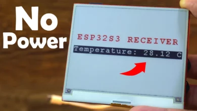
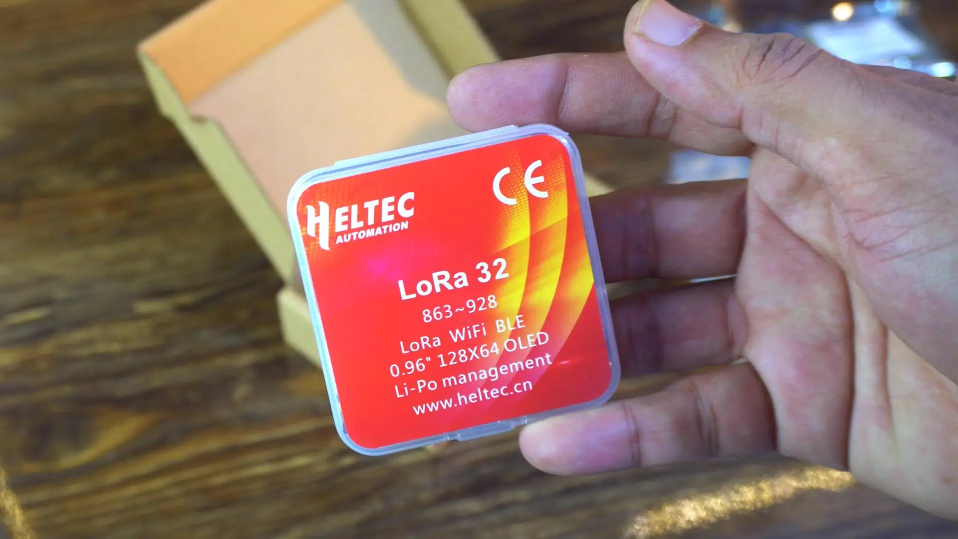
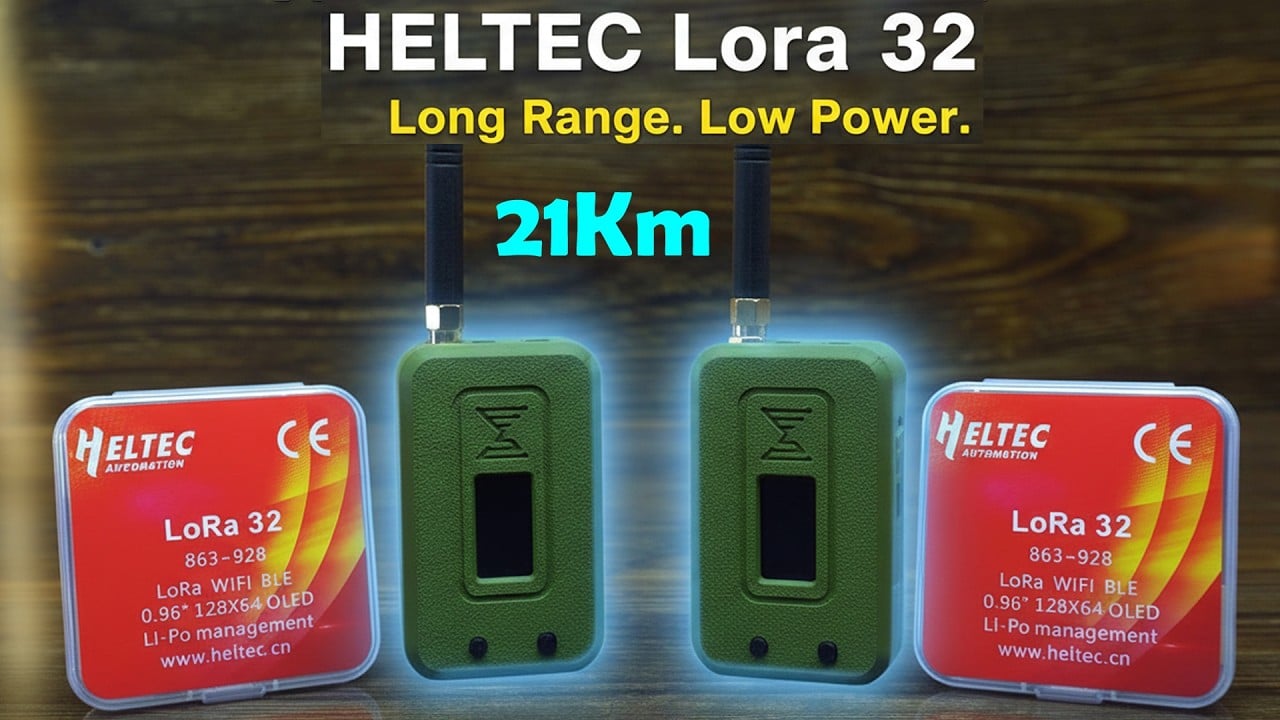
It is the Meshnology N35 ESP32 LoRa Board Kit / Heltec LoRa 32.
I have been waiting to get my hands on this for a long time. If you love long-range wireless communication, this kit is going to blow your mind.
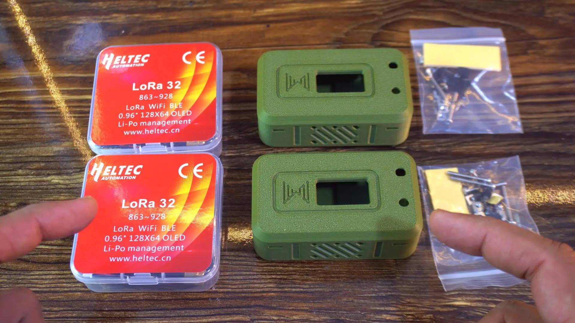
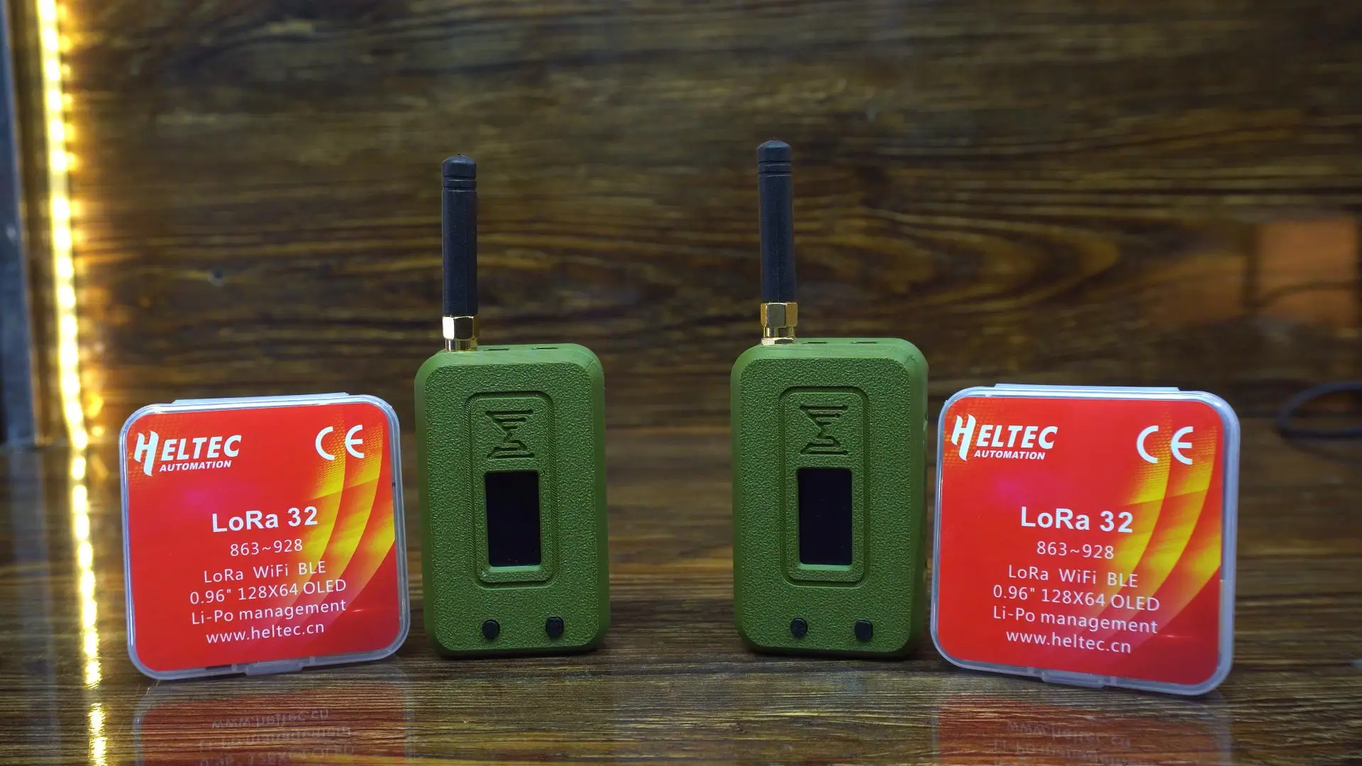
So this is everything I received in the package. First, I have two Heltec LoRa 32 boards. These are the classic ESP32 LoRa boards with a 0.96-inch OLED display right on top. They support LoRa, Wi-Fi, and Bluetooth.
Next, take a look at those two military-green protective cases. They already have the cutout for the OLED screen, buttons, and ventilation on the sides.
So right out of the box, you get two LoRa boards, two tough enclosures, and all the mounting hardware. Very neat, very thoughtful.
Let’s open the box and see what’s inside.
Alright, so inside the plastic casing, here is what we get.
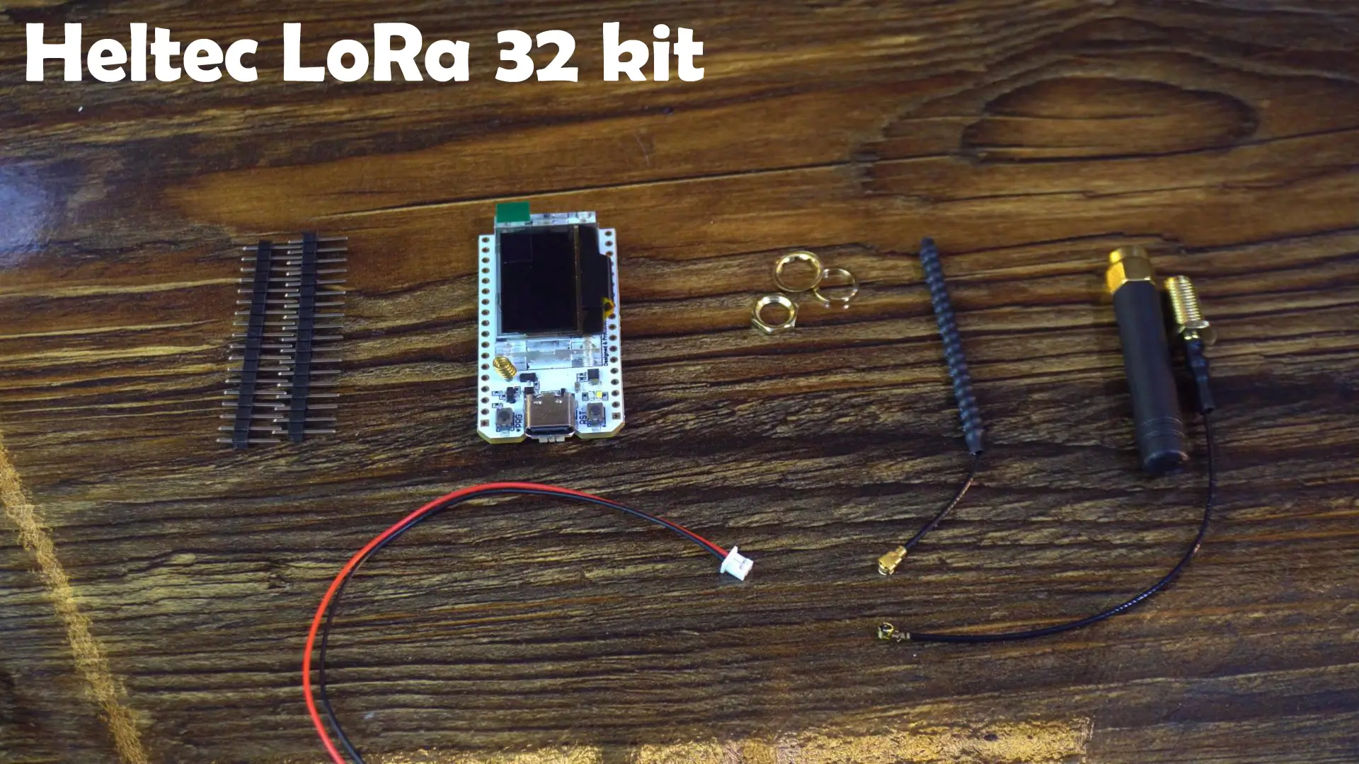
First, there are male header pins. These are going to be useful if I want to mount this board on a breadboard or connect external sensors. Good to see these included, because sometimes manufacturers skip them to cut costs.
Next, the star of the show: the LoRa development board itself. Clean layout, compact size, and a Type-C port. That already feels like an upgrade. No more struggling with micro-USB cables.
We also get two antennas. One flexible wire antenna for tight spaces and one stronger external antenna for long-range tests. Great to have both options right from the start.
There is also a small cable for connecting a Li-Po battery, which will be useful when we want to go fully wireless.
Everything you need is right here. No extra shopping required.
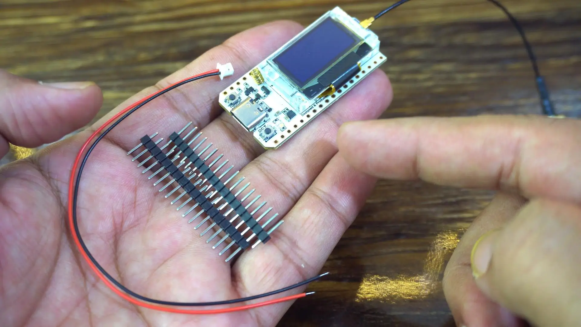
For now, I will keep things very simple. No soldering yet. No battery. I will power the board directly from my laptop or a 5V adapter and start with some initial tests.
If you plan to use this board for automation, then I definitely recommend soldering the headers, because you will need reliable connections for sensors and input/output pins. I have already made a lot of videos using different LoRa modules where I not only monitored sensors, but also controlled different loads over long distance.
For today, I want to keep everything simple and straightforward.
Amazon Links:
Other Tools and Components:
ESP32 WiFi + Bluetooth Module (Recommended)
Arduino Nano USB C type (Recommended)
*Please Note: These are affiliate links. I may make a commission if you buy the components through these links. I would appreciate your support in this way!
Okay, so before we go deeper, let me make one thing clear. All the basic specs and intro details are already available right here on the official product page. You can read everything in detail any time. I am not going to waste your time explaining what is already written.
Instead, we will quickly walk through this page together and focus only on what actually matters for real projects.
Now check this out.
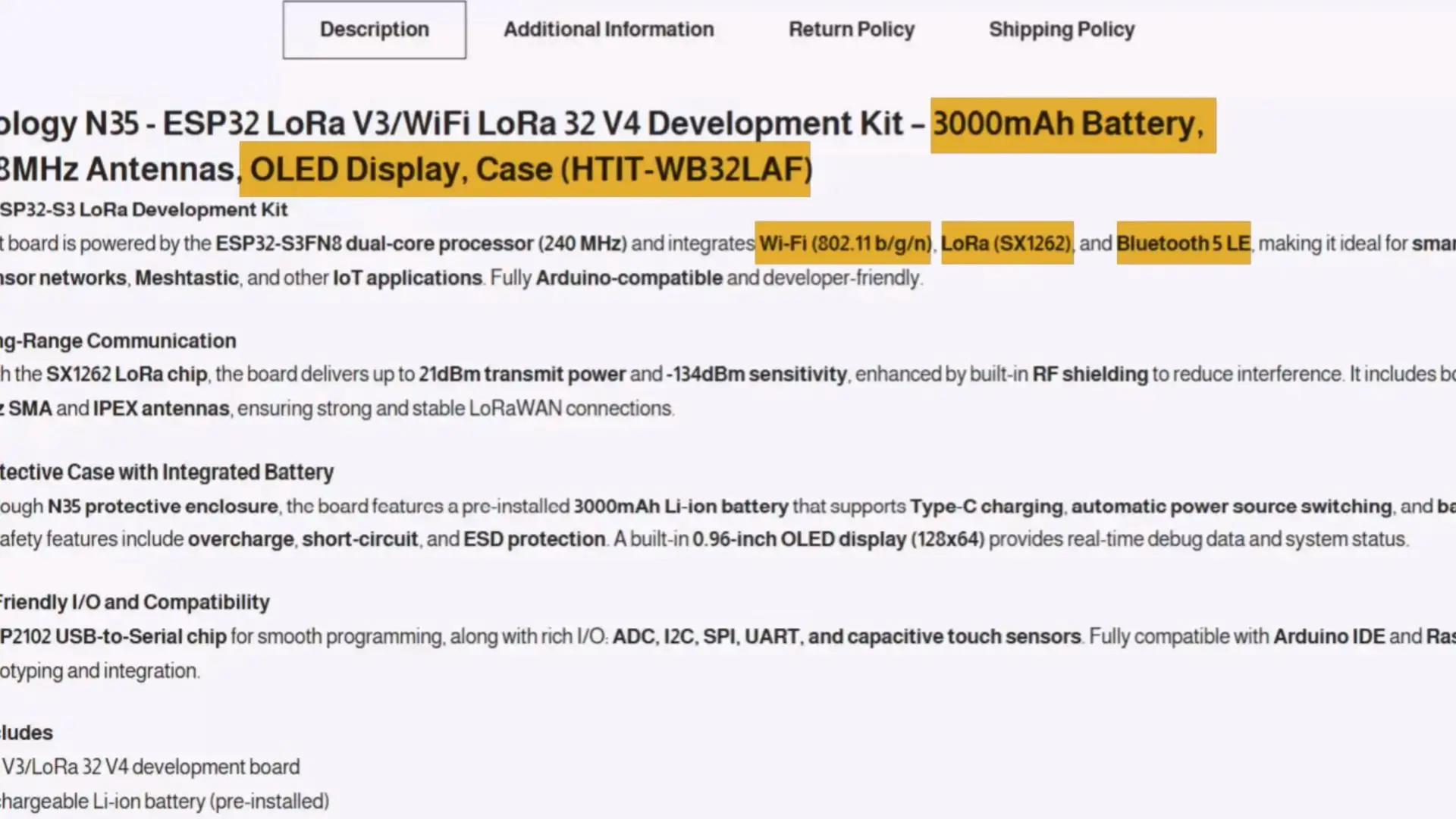
This is the Meshnology N35 ESP32 LoRa V3 / WiFi LoRa 32 V4 Development Kit. It says All-in-One ESP32-S3 LoRa Development Kit, and honestly, that is exactly what this is.
Wi-Fi, Bluetooth, LoRa, battery, display, case. Everything built right in.
Here they show the long-range communication details. SX1262 chip, up to 21dBm output and seriously good sensitivity. If you do Meshtastic or LoRaWAN nodes, that number matters.
Then here we have the case and battery features. A 3000mAh battery already installed inside the enclosure. USB-C charging and protection circuits are all included. There is a small OLED display, which helps a lot when you want instant debugging without plugging into a PC.
Next part: Developer friendly I/O.
All the important interfaces are available: ADC, I2C, SPI, UART, plus capacitive touch. That means you can attach sensors, GPS modules, displays, almost anything you want. It is fully Arduino compatible. You can even use it with a Raspberry Pi.
Now this is the part everyone gets confused about. V3 vs V4.
| Feature | ESP32 LoRa 32 V3 | WiFi LoRa 32 V4 (Upgraded) |
| Main MCU | ESP32-S3FN8, dual-core, up to 240MHz | ESP32-S3R2, dual-core, 2MB PSRAM, 16MB Flash |
| LoRa Chip | SX1262 | SX1262 |
| USB Interface | Type-C, with voltage regulation & ESD protection | Type-C, with voltage regulation, ESD, short-circuit protection, RF isolation |
| USB-to-Serial Chip | Integrated CP2102 | Removed – simpler design, lower cost |
| Display | 0.96″ 128×64 OLED | 0.96″ OLED (with PC casing protection) |
| Antenna | 2.4GHz spring antenna | Integrated FPC 2.4GHz antenna with casing + IPEX connector |
| Battery Interface | SH1.25-2, with charge/discharge management | SH1.25-2, optimized management, solar panel input (4.4–6V / ≤540mA) |
| GPS Interface | Not available | Added SH1.25-8Pin GNSS interface |
| Wireless Connectivity | Wi-Fi b/g/n, Bluetooth 5 (LE), LoRa | Wi-Fi b/g/n, Bluetooth 5 (LE), LoRa |
| Memory | 384KB ROM, 512KB SRAM, 16KB RTC SRAM, 8MB Flash | 2MB PSRAM + 16MB Flash |
| LoRa TX Power | 21 ±1dBm | 27 ±1dBm (High Power Upgrade) |
| Power Consumption | Low-power design | Ultra-low <20μA, GNSS power independently controllable |
| Dimensions | 50.2 × 25.5 × 10.2 mm | Similar footprint (V3 pin-compatible) |
| Operating Temp. | -20 ~ 70 ℃ | -20 ~ 70 ℃ |
| Development Support | Arduino IDE | Arduino + extended compatibility |
| Notable Extras | CP2102 for programming/debug | Solar input, stronger LoRa, GNSS, casing protection |
So look at this table. V4 has noticeable upgrades over V3.
More memory.
Higher LoRa transmit power.
Solar panel support.
GNSS expansion port.
Better protection on the casing and antennas.
Lower power consumption.
This is very important if you want long-term outdoor deployment.
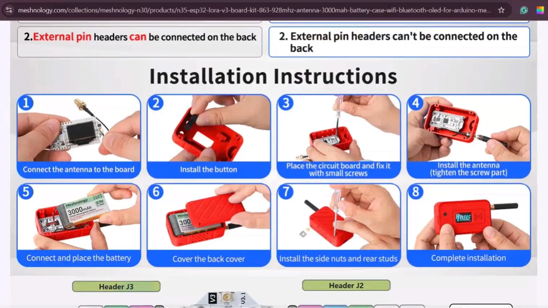
And it’s not just the basic details. On this same page, they have also provided the full installation instructions.
There is a complete pinout diagram,
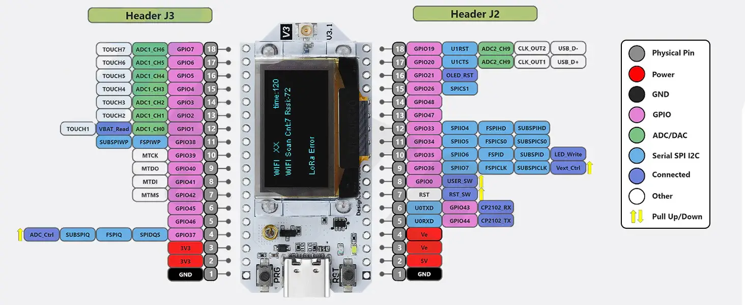
And every onboard component is clearly labeled,
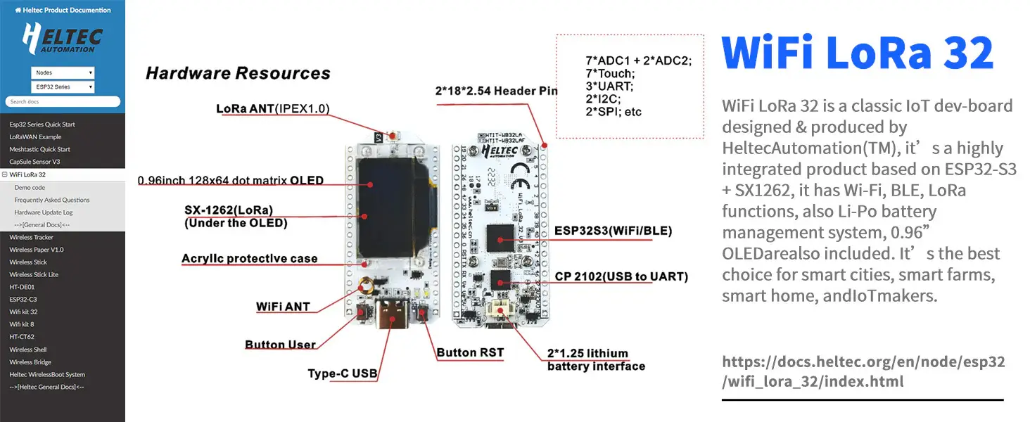
So you instantly know what is what. Plus, there is a lot more useful information available right here on this page if you want to explore further. Now, let’s go ahead and start with the board installation.
Heltec ESP32 Board installation:
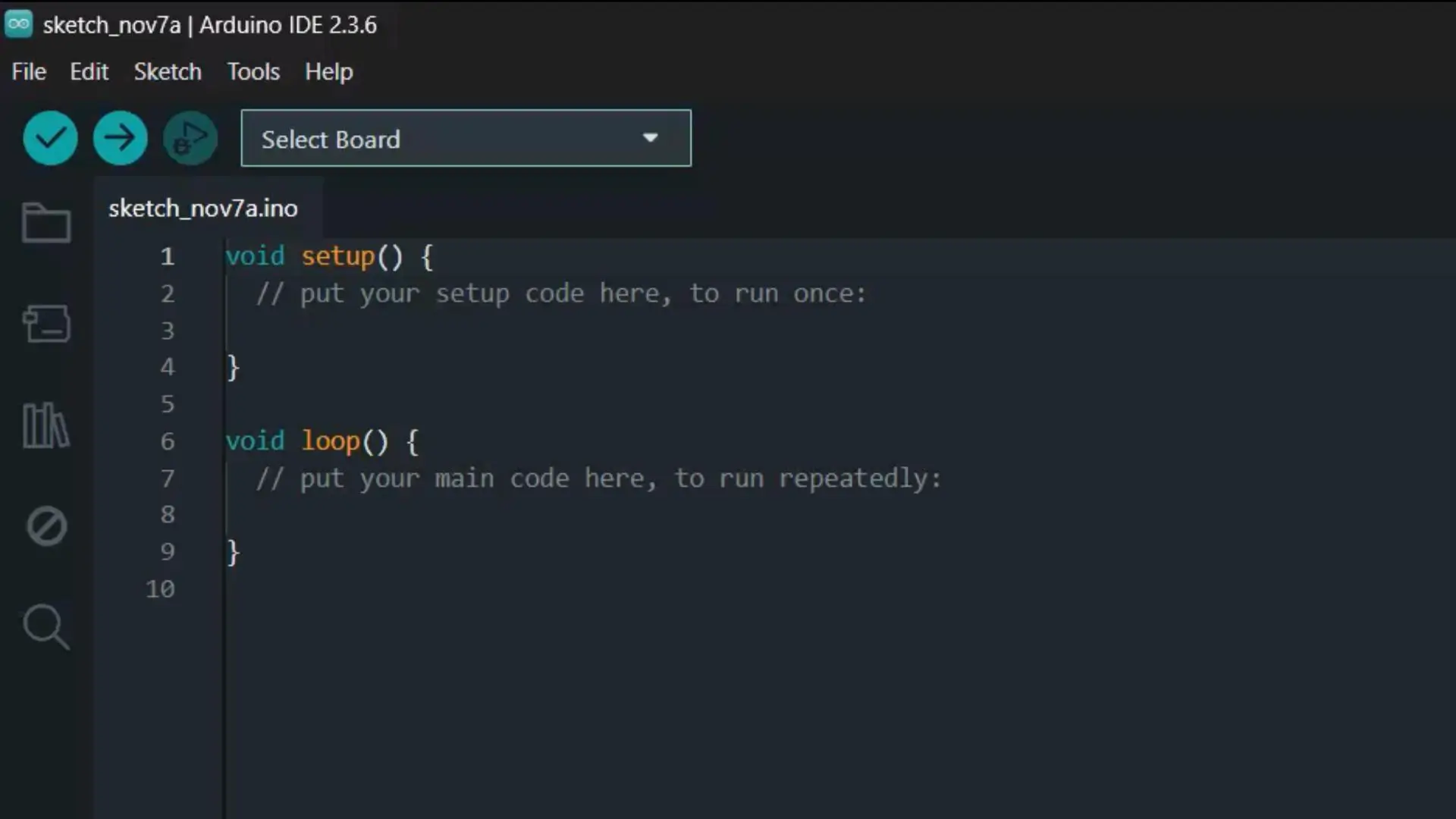
Make sure you have the latest version of the Arduino IDE installed on your system. As you can see, I am using Arduino IDE version 2.3.6.
After installing the Arduino IDE, you will see notification messages like: “Updates are available for some of your libraries” and “Updates are available for some of your boards.”
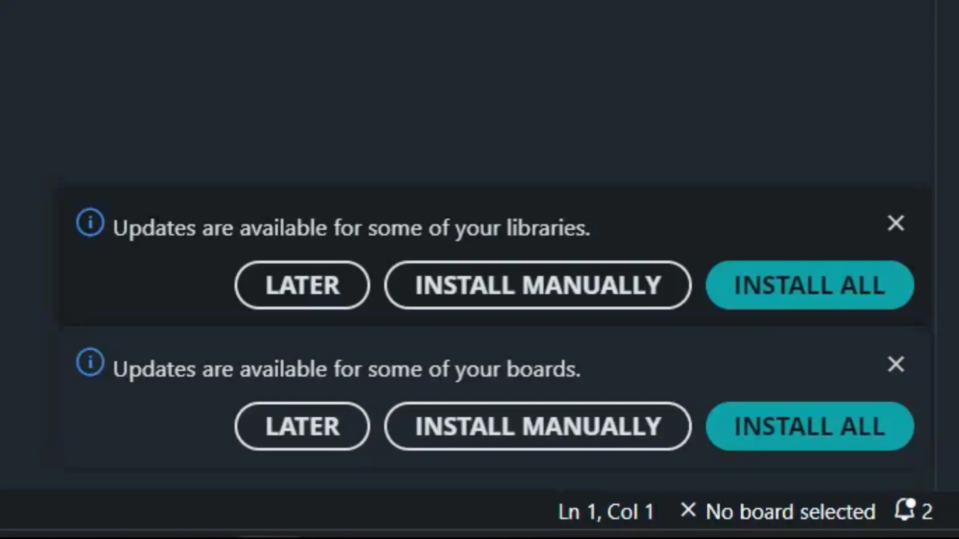
If you don’t want to update the libraries, that’s completely fine; because some projects require specific library versions.
However, you must install or update the boards, otherwise the Heltec ESP32 Dev Board won’t appear in the search results.
So, let’s go ahead and update it.
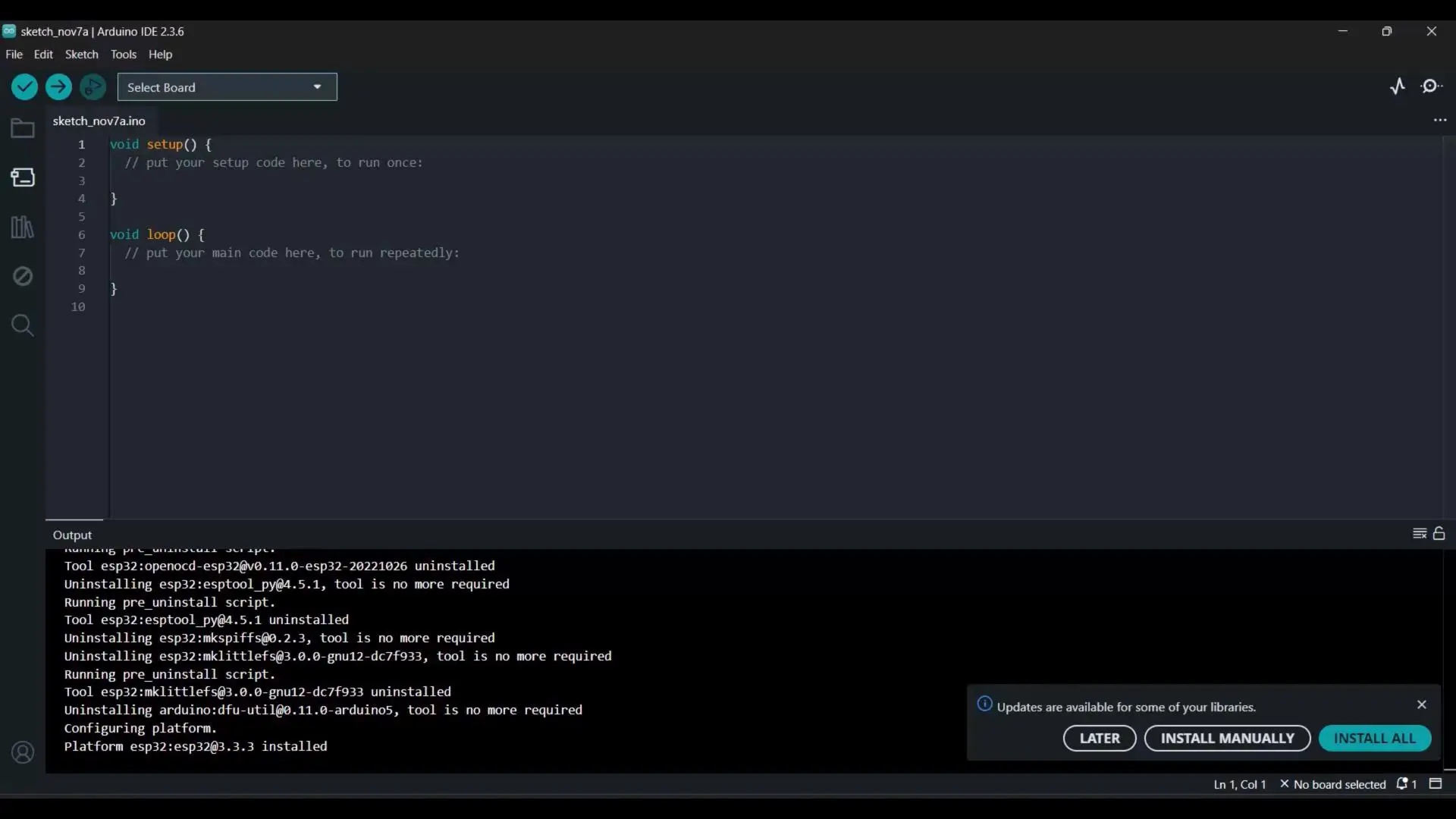
As you can see; I only updated the boards.
Next, go to the Boards Manager; search for Heltec ESP32, and as you can see, I have already installed it.
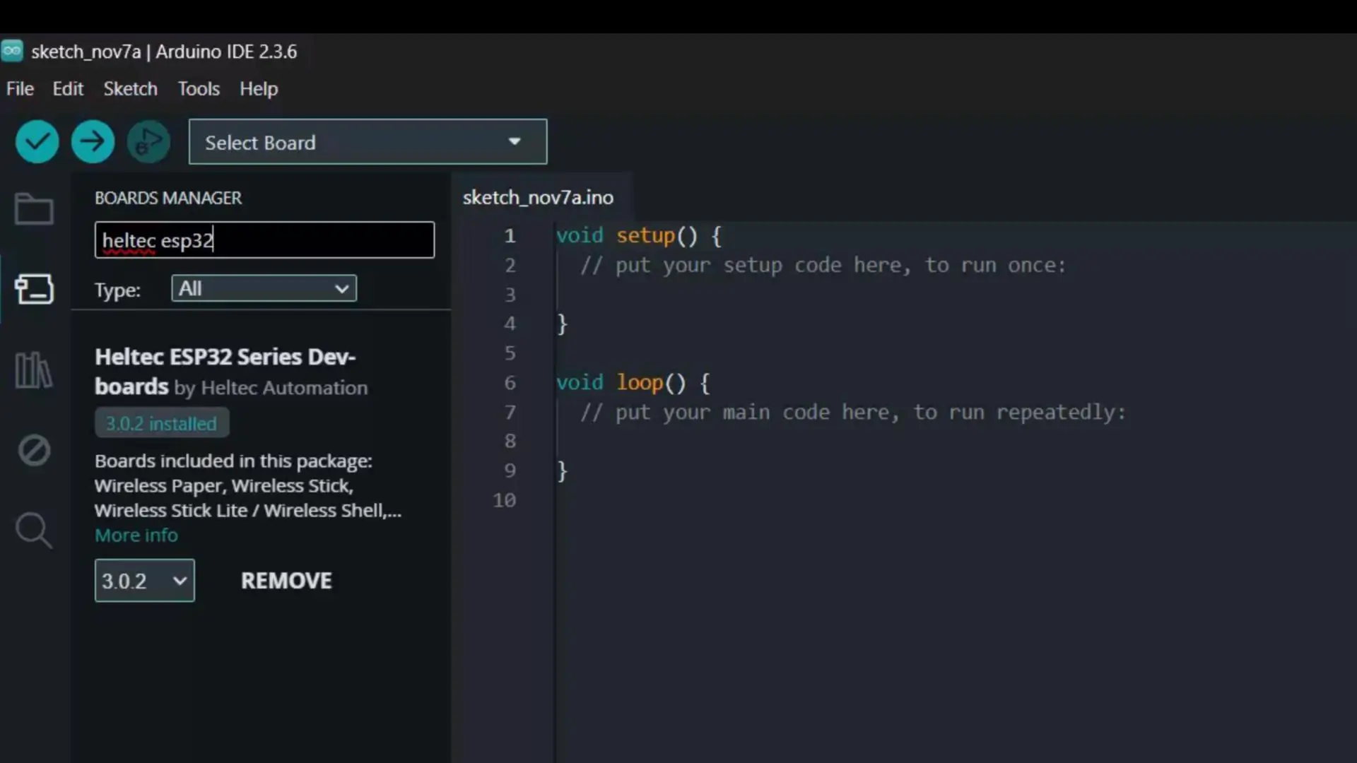
After this, you will also need to install the corresponding library.
Library Installation:
To do this, go to the Library Manager and search for Heltec ESP32.
Currently, version 2.1.5 is installed, which is the latest one.
And that’s it; you are all set.
Heltec LoRa 32 Testing:
Connect your Heltec LoRa 32 Development Board to your laptop or PC.
Then, go to the File menu → Examples → and look for Heltec ESP32 Dev-Boards.
You will see a lot of categories, and each category contains multiple examples for different boards.
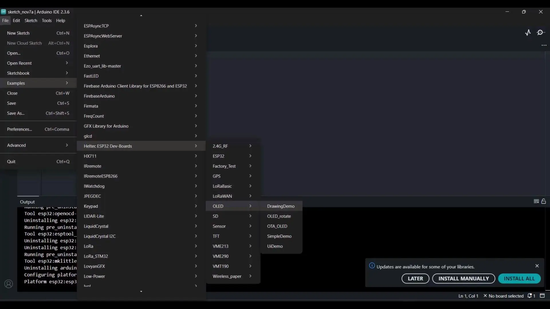
Since my main goal here is to test the boards and verify whether I can upload the code successfully, let’s go to the OLED category and open the DrawingDemo example.
Uploading the Code:
To upload the program, go to the Tools menu → Board → Heltec ESP32 Series Dev-boards, and select WiFi LoRa 32 (V3).
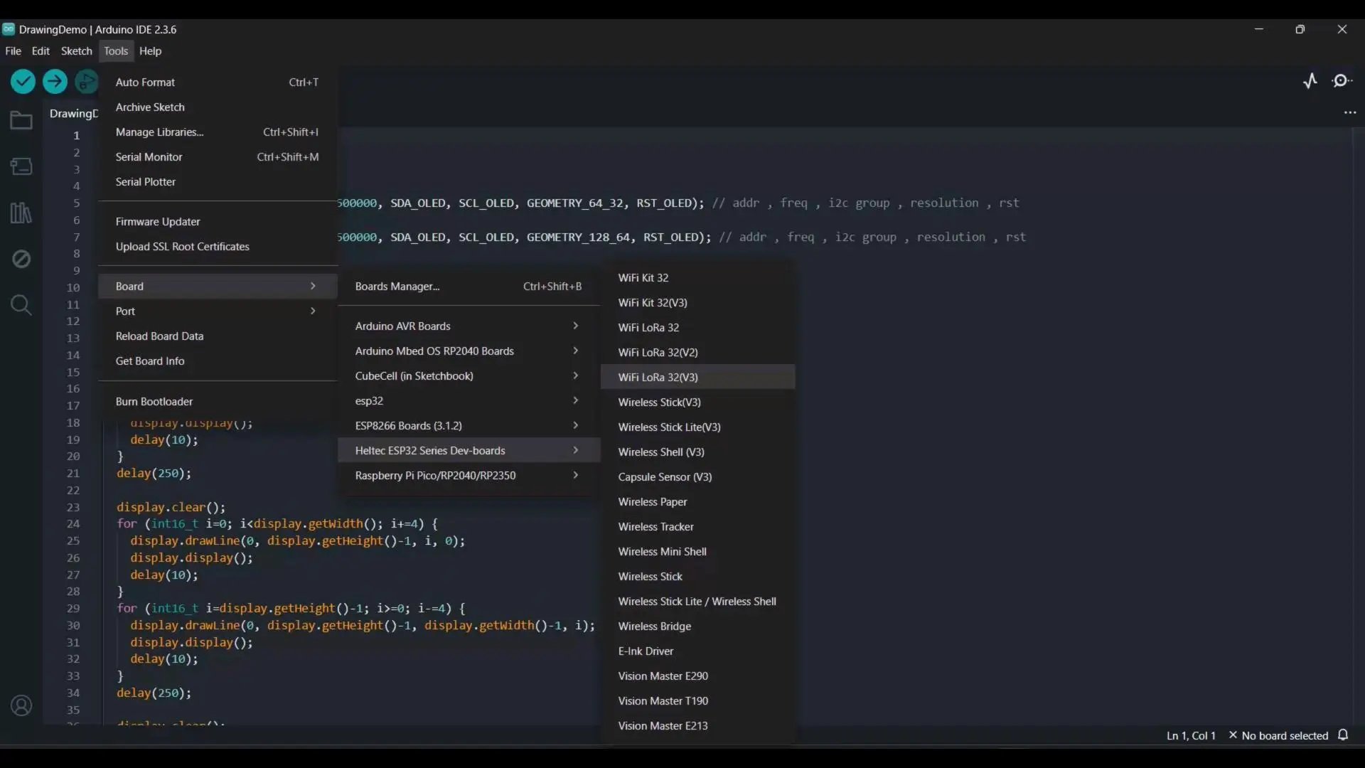
Next, select the correct communication port, and finally click on the Upload button.
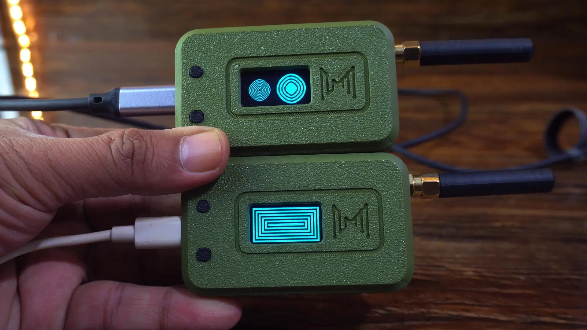
As you can see, both LoRa 32 development boards are working perfectly.
I have uploaded different codes to both boards for testing.
From this point onward, things become much easier; because I have already prepared two examples for you: one for one-way communication and another for two-way communication.
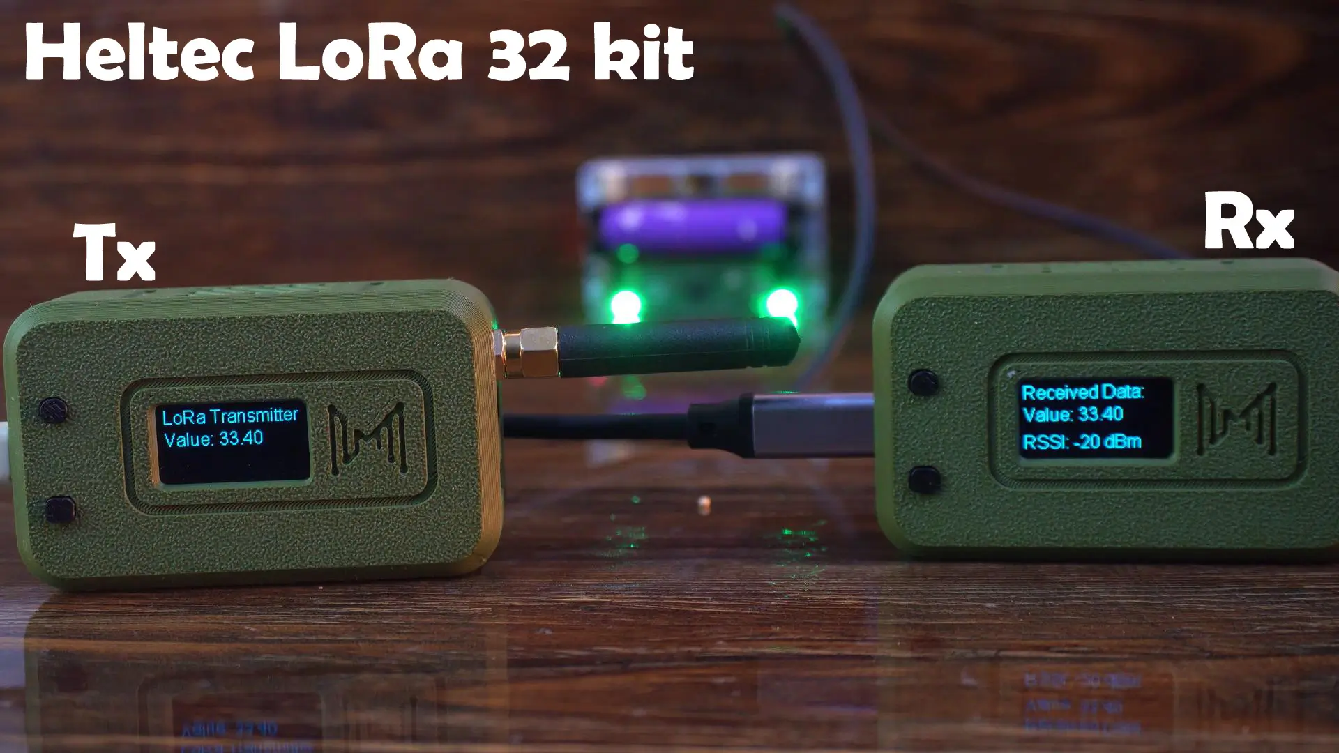
One-way communication between Heltec LoRa 32:
Transmitter Code:
|
1 2 3 4 5 6 7 8 9 10 11 12 13 14 15 16 17 18 19 20 21 22 23 24 25 26 27 28 29 30 31 32 33 34 35 36 37 38 39 40 41 42 43 44 45 46 47 48 49 50 51 52 53 54 55 56 57 58 59 60 61 62 63 64 65 66 67 68 69 70 71 72 73 74 75 76 77 78 79 80 81 82 83 84 85 86 87 88 89 90 91 92 93 94 95 96 97 98 99 100 101 102 103 104 105 106 107 108 109 110 111 112 113 |
/* * Heltec WiFi LoRa 32 V3 - Transmitter with OLED Display * * Sends numeric values through LoRa and continuously shows the latest sensor value on OLED. * * Libraries used: * - LoRaWan_APP.h (Heltec) * - HT_SSD1306Wire.h (for OLED) */ #include "LoRaWan_APP.h" #include <Wire.h> #include "HT_SSD1306Wire.h" //================ OLED SETUP ================// static SSD1306Wire display(0x3c, 500000, SDA_OLED, SCL_OLED, GEOMETRY_128_64, RST_OLED); void VextON(void) { pinMode(Vext, OUTPUT); digitalWrite(Vext, LOW); // Power ON for OLED } void VextOFF(void) { pinMode(Vext, OUTPUT); digitalWrite(Vext, HIGH); } //================ LORA SETUP ================// #define RF_FREQUENCY 915000000 // Hz #define TX_OUTPUT_POWER 5 // dBm #define LORA_BANDWIDTH 0 #define LORA_SPREADING_FACTOR 7 #define LORA_CODINGRATE 1 #define LORA_PREAMBLE_LENGTH 8 #define LORA_SYMBOL_TIMEOUT 0 #define LORA_FIX_LENGTH_PAYLOAD_ON false #define LORA_IQ_INVERSION_ON false #define RX_TIMEOUT_VALUE 1000 #define BUFFER_SIZE 50 char txpacket[BUFFER_SIZE]; bool lora_idle = true; float sensorValue = 0.0; static RadioEvents_t RadioEvents; void OnTxDone(void); void OnTxTimeout(void); //================ SETUP =================// void setup() { Serial.begin(115200); Mcu.begin(HELTEC_BOARD, SLOW_CLK_TPYE); // Power on and initialize OLED VextON(); delay(100); display.init(); display.setFont(ArialMT_Plain_16); display.clear(); display.drawString(0, 0, "LoRa TX + OLED"); display.display(); delay(1000); // Initialize LoRa RadioEvents.TxDone = OnTxDone; RadioEvents.TxTimeout = OnTxTimeout; Radio.Init(&RadioEvents); Radio.SetChannel(RF_FREQUENCY); Radio.SetTxConfig(MODEM_LORA, TX_OUTPUT_POWER, 0, LORA_BANDWIDTH, LORA_SPREADING_FACTOR, LORA_CODINGRATE, LORA_PREAMBLE_LENGTH, LORA_FIX_LENGTH_PAYLOAD_ON, true, 0, 0, LORA_IQ_INVERSION_ON, 3000); } //================ LOOP =================// void loop() { if (lora_idle == true) { delay(2000); // Simulate sensor data (replace with analogRead for real sensor) sensorValue = random(100, 1000) / 10.0; sprintf(txpacket, "Value: %.2f", sensorValue); Serial.printf("\r\nSending packet: \"%s\" , length %d\r\n", txpacket, strlen(txpacket)); // ==== DISPLAY LIVE SENSOR VALUE ==== // display.clear(); display.setTextAlignment(TEXT_ALIGN_LEFT); display.drawString(0, 0, "LoRa Transmitter"); display.drawString(0, 20, txpacket); display.display(); // ==== SEND VIA LORA ==== // Radio.Send((uint8_t *)txpacket, strlen(txpacket)); lora_idle = false; } Radio.IrqProcess(); } //================ CALLBACKS =================// // We don't want to overwrite OLED anymore — only update lora_idle void OnTxDone(void) { Serial.println("TX done..."); lora_idle = true; } void OnTxTimeout(void) { Radio.Sleep(); Serial.println("TX timeout..."); lora_idle = true; } |
Receiver Code:
|
1 2 3 4 5 6 7 8 9 10 11 12 13 14 15 16 17 18 19 20 21 22 23 24 25 26 27 28 29 30 31 32 33 34 35 36 37 38 39 40 41 42 43 44 45 46 47 48 49 50 51 52 53 54 55 56 57 58 59 60 61 62 63 64 65 66 67 68 69 70 71 72 73 74 75 76 77 78 79 80 81 82 83 84 85 86 87 88 89 90 91 92 93 94 95 96 97 98 99 100 101 102 103 104 105 106 107 108 109 110 |
/* * Heltec WiFi LoRa 32 V3 - Receiver with OLED Display * * Receives LoRa packets and displays the received value + RSSI on OLED. * * Libraries used: * - LoRaWan_APP.h (Heltec) * - HT_SSD1306Wire.h (for OLED display) */ #include "LoRaWan_APP.h" #include "Arduino.h" #include <Wire.h> #include "HT_SSD1306Wire.h" //================ OLED SETUP ================// static SSD1306Wire display(0x3c, 500000, SDA_OLED, SCL_OLED, GEOMETRY_128_64, RST_OLED); void VextON(void) { pinMode(Vext, OUTPUT); digitalWrite(Vext, LOW); // Power ON for OLED } void VextOFF(void) { pinMode(Vext, OUTPUT); digitalWrite(Vext, HIGH); } //================ LORA CONFIG ================// #define RF_FREQUENCY 915000000 // Hz #define TX_OUTPUT_POWER 14 // dBm #define LORA_BANDWIDTH 0 #define LORA_SPREADING_FACTOR 7 #define LORA_CODINGRATE 1 #define LORA_PREAMBLE_LENGTH 8 #define LORA_SYMBOL_TIMEOUT 0 #define LORA_FIX_LENGTH_PAYLOAD_ON false #define LORA_IQ_INVERSION_ON false #define RX_TIMEOUT_VALUE 1000 #define BUFFER_SIZE 50 char rxpacket[BUFFER_SIZE]; bool lora_idle = true; static RadioEvents_t RadioEvents; int16_t rssiValue; uint16_t rxSize; //================ SETUP =================// void setup() { Serial.begin(115200); Mcu.begin(HELTEC_BOARD, SLOW_CLK_TPYE); // Power ON and initialize OLED VextON(); delay(100); display.init(); display.setFont(ArialMT_Plain_16); display.clear(); display.drawString(0, 0, "LoRa RX + OLED"); display.display(); delay(1000); // Initialize LoRa receiver RadioEvents.RxDone = OnRxDone; Radio.Init(&RadioEvents); Radio.SetChannel(RF_FREQUENCY); Radio.SetRxConfig(MODEM_LORA, LORA_BANDWIDTH, LORA_SPREADING_FACTOR, LORA_CODINGRATE, 0, LORA_PREAMBLE_LENGTH, LORA_SYMBOL_TIMEOUT, LORA_FIX_LENGTH_PAYLOAD_ON, 0, true, 0, 0, LORA_IQ_INVERSION_ON, true); Serial.println("LoRa Receiver Initialized"); } //================ LOOP =================// void loop() { if (lora_idle) { lora_idle = false; Serial.println("Listening for LoRa packets..."); Radio.Rx(0); } Radio.IrqProcess(); } //================ CALLBACK =================// void OnRxDone(uint8_t *payload, uint16_t size, int16_t rssi, int8_t snr) { memcpy(rxpacket, payload, size); rxpacket[size] = '\0'; rssiValue = rssi; rxSize = size; Radio.Sleep(); // Print in Serial Monitor Serial.printf("\r\nReceived packet: \"%s\" | RSSI: %d | Size: %d\r\n", rxpacket, rssiValue, rxSize); // ==== SHOW ON OLED ==== // display.clear(); display.setTextAlignment(TEXT_ALIGN_LEFT); display.drawString(0, 0, "Received Data:"); display.drawString(0, 20, String(rxpacket)); display.drawString(0, 45, "RSSI: " + String(rssiValue) + " dBm"); display.display(); lora_idle = true; } |
I have already uploaded both programs; so, let’s go ahead and see them in action!
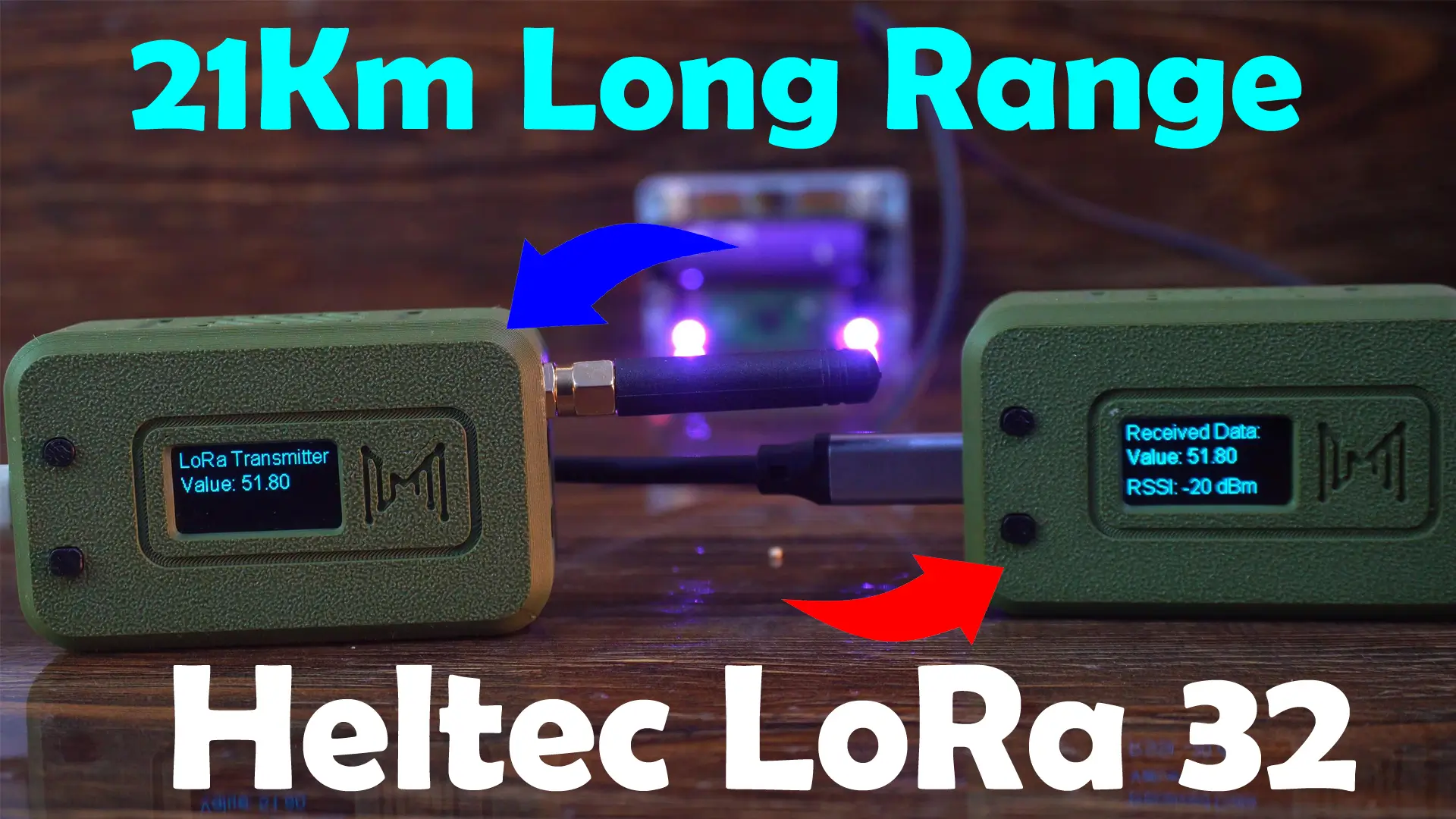
Practical Demonstration:
The transmitter side is currently sending a random value, and the receiver side is successfully receiving it.
Instead of sending a random value, you can connect a sensor or a button and transmit its readings to the receiver; allowing you to monitor the sensor data or button state remotely.
In fact, you can even connect multiple input devices and send all their values together as a string message to the receiver.
Now, let’s disconnect the transmitter side so you can clearly see that this is a real wireless communication.
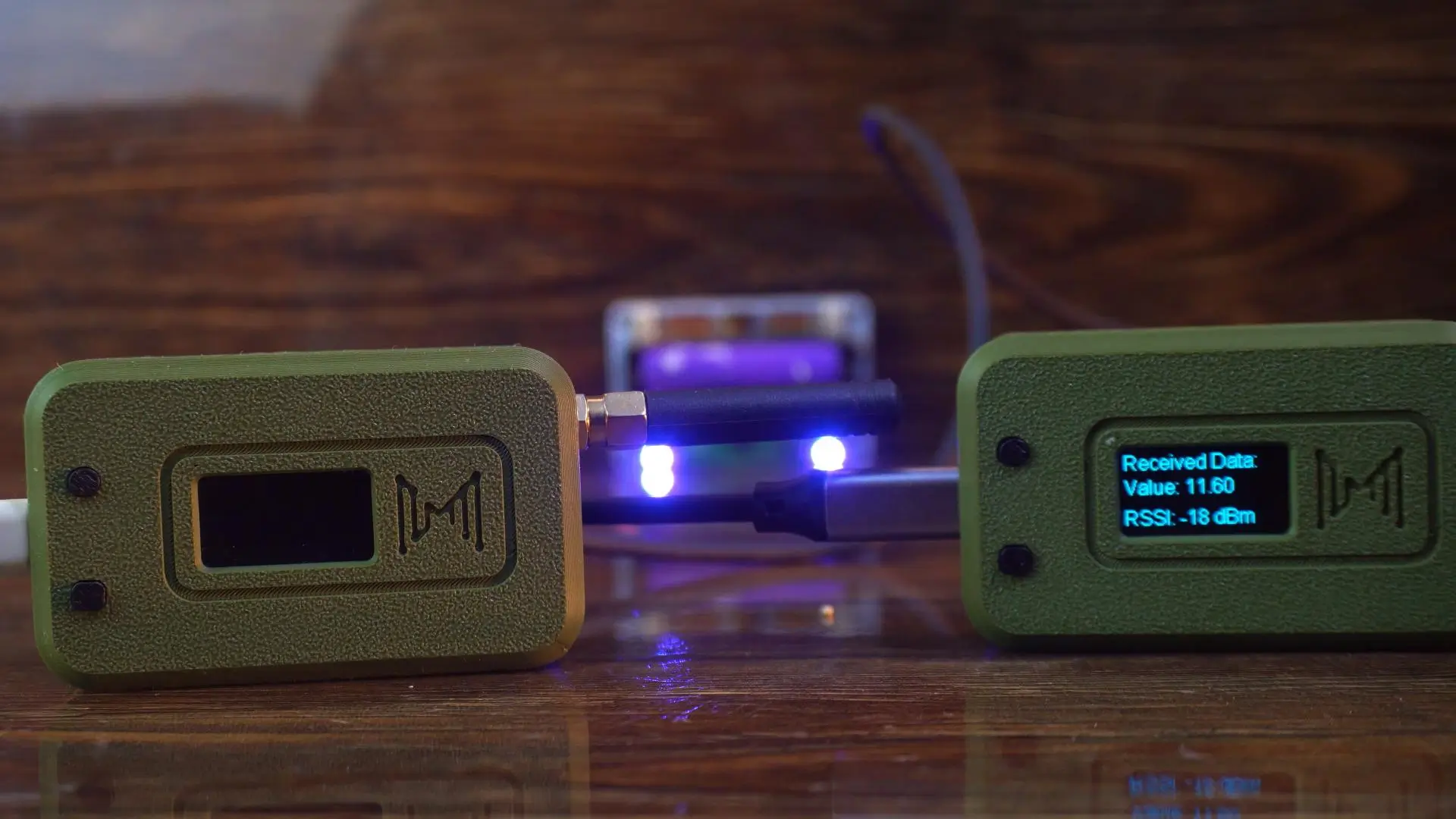
After disconnecting the transmitter, you can see that the value on the receiver side is no longer updating.
Let’s power the transmitter back on…
And as soon as I turned it on, the receiver side started updating the value in real time again.
Two-way communication between Heltec LoRa 32:
This program is designed to demonstrate two-way communication.
It not only sends a random value, but also receives and displays the incoming value on the screen.
I have uploaded the same code to both Heltec LoRa 32 Development Boards; so, let’s go ahead and see it in action!
|
1 2 3 4 5 6 7 8 9 10 11 12 13 14 15 16 17 18 19 20 21 22 23 24 25 26 27 28 29 30 31 32 33 34 35 36 37 38 39 40 41 42 43 44 45 46 47 48 49 50 51 52 53 54 55 56 57 58 59 60 61 62 63 64 65 66 67 68 69 70 71 72 73 74 75 76 77 78 79 80 81 82 83 84 85 86 87 88 89 90 91 92 93 94 95 96 97 98 99 100 101 102 103 104 105 106 107 108 109 110 111 112 113 114 115 116 117 118 119 120 121 122 123 124 125 126 127 128 129 130 131 132 133 134 135 136 137 138 139 140 141 142 |
/* * Heltec WiFi LoRa 32 V3 - Two-Way Communication with OLED * * Each device both transmits and receives LoRa packets. * Displays local and remote values on OLED. */ #include "LoRaWan_APP.h" #include <Wire.h> #include "HT_SSD1306Wire.h" //================ OLED SETUP ================// static SSD1306Wire display(0x3c, 500000, SDA_OLED, SCL_OLED, GEOMETRY_128_64, RST_OLED); void VextON(void) { pinMode(Vext, OUTPUT); digitalWrite(Vext, LOW); } //================ LORA CONFIG ================// #define RF_FREQUENCY 915000000 // Hz #define TX_OUTPUT_POWER 5 #define LORA_BANDWIDTH 0 #define LORA_SPREADING_FACTOR 7 #define LORA_CODINGRATE 1 #define LORA_PREAMBLE_LENGTH 8 #define LORA_SYMBOL_TIMEOUT 0 #define LORA_FIX_LENGTH_PAYLOAD_ON false #define LORA_IQ_INVERSION_ON false #define RX_TIMEOUT_VALUE 1000 #define BUFFER_SIZE 64 //================ VARIABLES ================// char txpacket[BUFFER_SIZE]; char rxpacket[BUFFER_SIZE]; bool lora_idle = true; float localValue = 0.0; float remoteValue = 0.0; static RadioEvents_t RadioEvents; void OnTxDone(void); void OnTxTimeout(void); void OnRxDone(uint8_t *payload, uint16_t size, int16_t rssi, int8_t snr); unsigned long lastSend = 0; const unsigned long sendInterval = 4000; // every 4 s //================ SETUP =================// void setup() { Serial.begin(115200); Mcu.begin(HELTEC_BOARD, SLOW_CLK_TPYE); VextON(); delay(100); display.init(); display.setFont(ArialMT_Plain_16); display.clear(); display.drawString(0, 0, "LoRa Two-Way"); display.display(); delay(1000); // LoRa setup RadioEvents.TxDone = OnTxDone; RadioEvents.TxTimeout = OnTxTimeout; RadioEvents.RxDone = OnRxDone; Radio.Init(&RadioEvents); Radio.SetChannel(RF_FREQUENCY); Radio.SetTxConfig(MODEM_LORA, TX_OUTPUT_POWER, 0, LORA_BANDWIDTH, LORA_SPREADING_FACTOR, LORA_CODINGRATE, LORA_PREAMBLE_LENGTH, LORA_FIX_LENGTH_PAYLOAD_ON, true, 0, 0, LORA_IQ_INVERSION_ON, 3000); Radio.SetRxConfig(MODEM_LORA, LORA_BANDWIDTH, LORA_SPREADING_FACTOR, LORA_CODINGRATE, 0, LORA_PREAMBLE_LENGTH, LORA_SYMBOL_TIMEOUT, LORA_FIX_LENGTH_PAYLOAD_ON, 0, true, 0, 0, LORA_IQ_INVERSION_ON, true); lora_idle = true; Radio.Rx(0); } //================ LOOP =================// void loop() { // Periodically send data if (millis() - lastSend > sendInterval && lora_idle) { lastSend = millis(); localValue = random(100, 999) / 10.0; // Simulated sensor value sprintf(txpacket, "Local: %.2f", localValue); Serial.printf("\r\nSending packet: \"%s\"\r\n", txpacket); Radio.Send((uint8_t *)txpacket, strlen(txpacket)); lora_idle = false; } Radio.IrqProcess(); // ==== Display OLED continuously ==== display.clear(); display.setTextAlignment(TEXT_ALIGN_LEFT); display.drawString(0, 0, "LoRa Two-Way Link"); display.drawString(0, 20, "My Value: " + String(localValue, 2)); display.drawString(0, 40, "Rx Value: " + String(remoteValue, 2)); display.display(); delay(100); } //================ CALLBACKS =================// void OnTxDone(void) { Serial.println("TX done, switching to RX..."); lora_idle = true; Radio.Rx(0); } void OnTxTimeout(void) { Serial.println("TX timeout, retry RX..."); lora_idle = true; Radio.Rx(0); } void OnRxDone(uint8_t *payload, uint16_t size, int16_t rssi, int8_t snr) { memcpy(rxpacket, payload, size); rxpacket[size] = '\0'; Serial.printf("Received: \"%s\" | RSSI: %d\r\n", rxpacket, rssi); // Extract number from received string if possible String data = String(rxpacket); int idx = data.indexOf(':'); if (idx != -1) { remoteValue = data.substring(idx + 1).toFloat(); } else { remoteValue = 0; } Radio.Sleep(); lora_idle = true; Radio.Rx(0); // back to listening } |
Practical Demonstration:
You can clearly see on the displays that both boards are actively communicating with each other in real time.

This proves that our two-way LoRa communication setup is working perfectly.
In a real-world project, you could replace the random value with sensor data, button states, or any other input, allowing both devices to exchange information wirelessly over long distances.
In the next article, we will use these LoRa 32 Development boards to build a fully functional off-grid text messaging system, and we will also perform an extreme-range test. So, that’s all for now.
Watch Video Tutorial:
Discover more from Electronic Clinic
Subscribe to get the latest posts sent to your email.