RDK S100 GPIO Control Using GUI with PyQt5 and Qt Designer
Last Updated on March 9, 2026 by Engr. Shahzada Fahad
Table of Contents
RDK S100 GPIO Control Using GUI:
In this article, we demonstrate RDK S100 GPIO control using GUI built with Python and PyQt5 “Qt Designer”. This project shows how a desktop GUI can directly control real GPIO pins on the RDK S100 hardware, not a simulation.

This is the RDK S100, and this changes everything.
An edge AI board with 80 TOPS of AI power; running real-time computer vision.
And what you are seeing right now; is all happening live.
Note: For a practical demonstration, watch the video available on my YouTube channel, Electronic Clinic.
Amazon Links:
RDK S100 MCU Port Expansion Board
RDK S100 Camera Expansion Board
Other Tools and Components:
ESP32 WiFi + Bluetooth Module (Recommended)
Arduino Nano USB C type (Recommended)
*Please Note: These are affiliate links. I may make a commission if you buy the components through these links. I would appreciate your support in this way!
AI and Computer Vision Projects on RDK S100
The RDK S100 is powered by a dedicated BPU – Brain Processing Unit.
This BPU is designed only for AI.
That means ultra-fast vision, low latency, and high FPS; without stressing the CPU.
This is edge AI at a whole new level.
For the last two weeks, I have been working on this every single day; almost 12 hours a day.
And honestly, the projects I built for you using the RDK S100. They are going to surprise you.
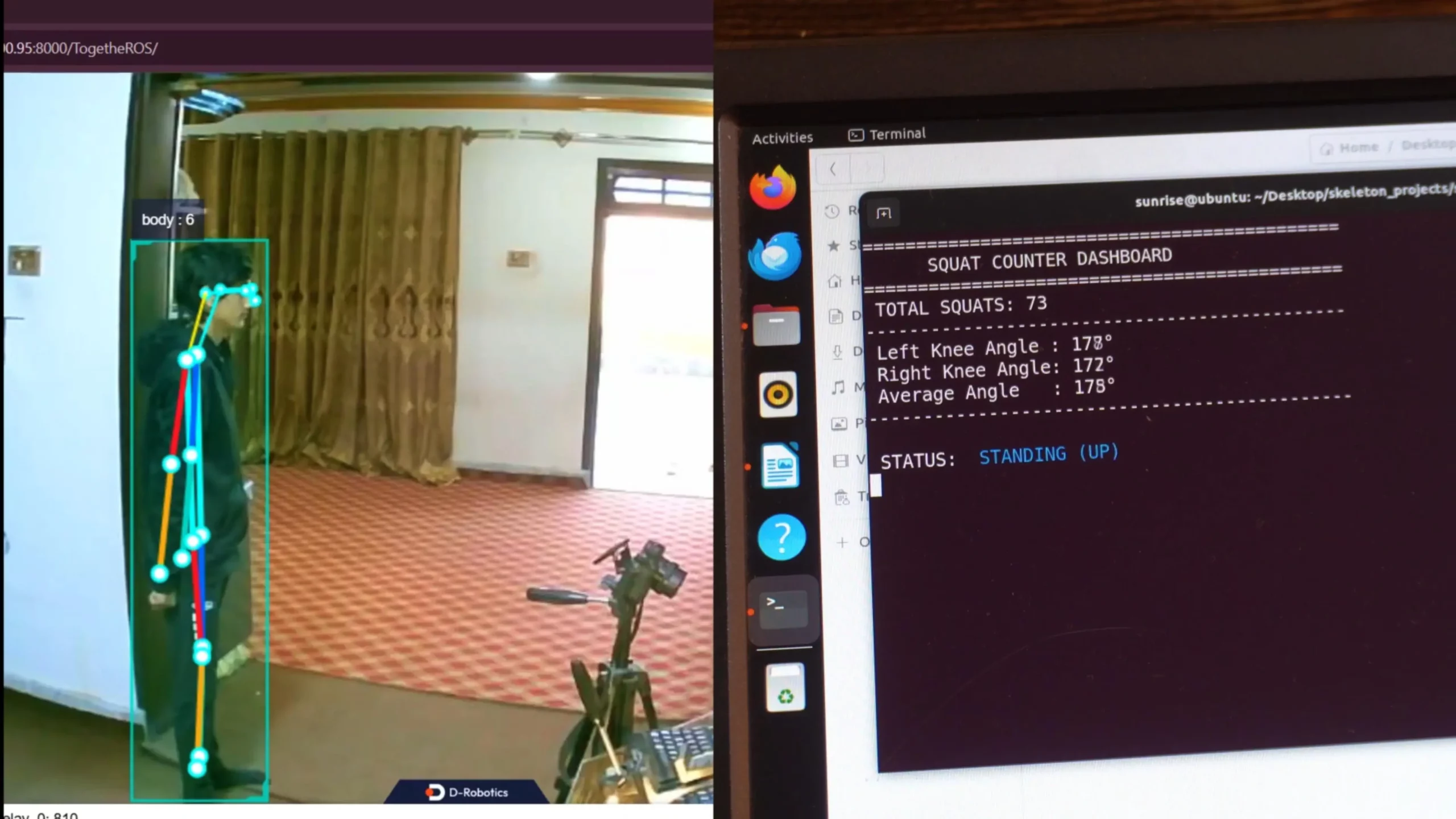
AI Squats Counter Using RDK S100
Just take a look at this squats counter dashboard.
It counts squats with an insane level of accuracy.
Look at the left knee angle and the right knee angle.

Do you see even a small lag?
Everything is happening so fast.
All in real time.
Virtual Laser Security System Using RDK S100

What if a security system worked like a laser trap?
But without any real lasers.
Using YOLOv5x, I built a virtual laser security system.
It watches everything and asks one smart question…

Is this person in the normal area or did they cross into the prohibited zone?
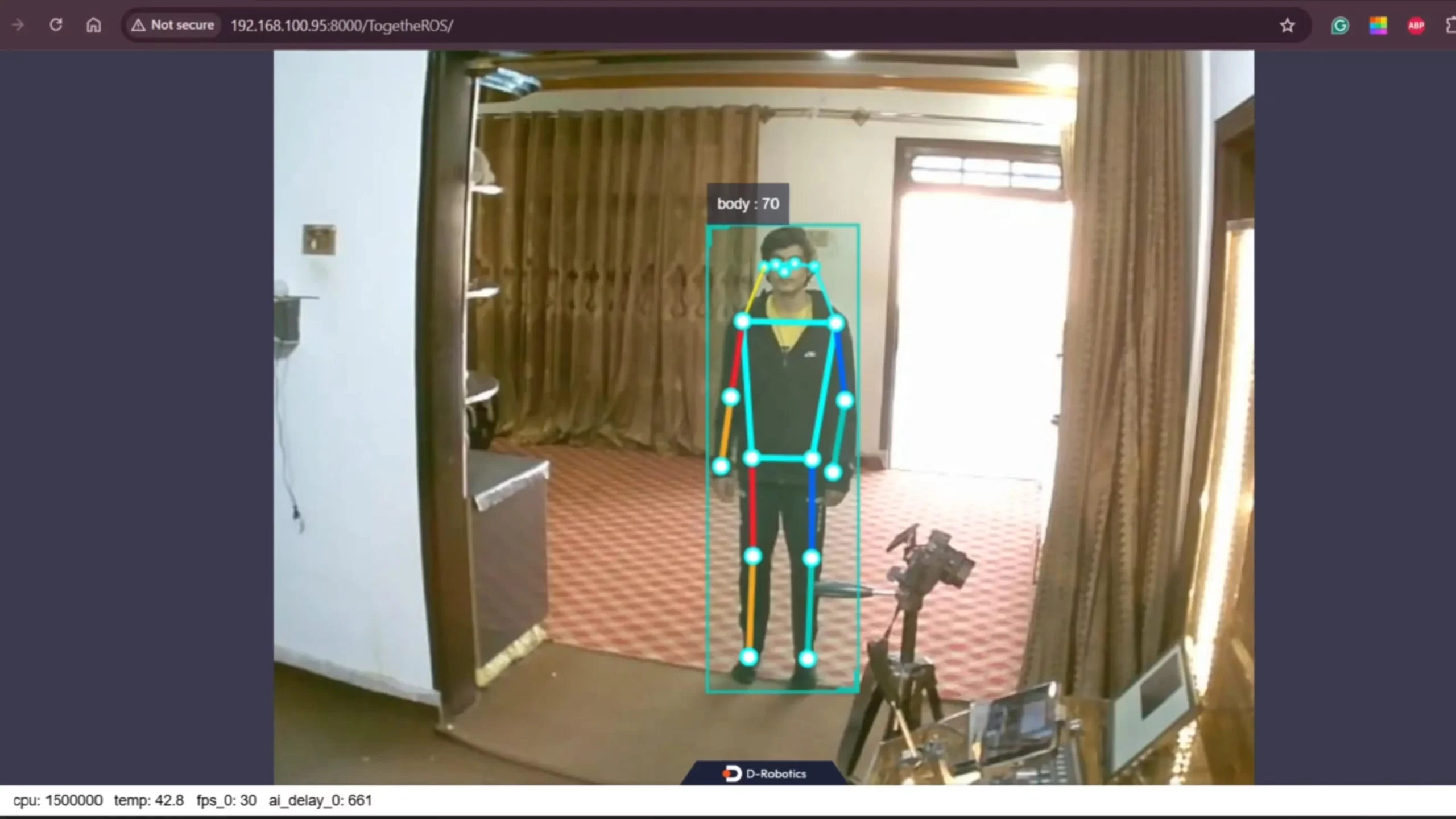
Radar Style Human Tracking System
And then I took it one step further.
I built a radar-style tracking system.
![]()
By default, it tracks everything.
But here’s the cool part; If I want to track only one object or only humans.
![]()
I can tell the system in real time; and instantly; the radar locks onto just that target.
AI Based Robotic Dog Project
Right now, I am working on something really exciting.
An AI-based robotic dog; designed for police use.

This robotic dog can help in search operations.
It can detect people and monitor a suspect’s body movements in real time.
For example;

If a suspect raises their hands; the robotic dog does nothing.
But the moment the suspect lowers their hands; the dog reacts immediately.

What happens next depends on the situation.
It could turn on a buzzer; shine a strong light, or take a more serious action. For demonstration purposes; I controlled an LED.
This is real AI controlling real hardware.
And when you control physical hardware; you must understand your system very well.
You need to know how to control pins and how to monitor them safely.
![]()
So if you think I should make a complete series on this; please like and share this article and the video. That helps me understand how many of you are interested.
And if you have any ideas; let me know in the comments.
RDK S100 GPIO Control Using GUI with PyQt5
So; today, we are starting simple.
We will control a GPIO pin.
Not just blinking it; but also through a GUI.
We will build a PyQt5 interface, to turn the LED ON and OFF.
And we will also display the LED status in real time.
if you want the original source code along with all the other resources; you can head over to my Patreon page.
Thank you so much for your support.
Hardware Setup for RDK S100 GPIO Control

In the getting started article, I first connected a stereo camera and the MCU expansion board with the RDK S100.
But then I realized something.
I have already used the stereo camera with the RDK X5.
So this time, why not use a simple USB camera?

Last time, I connected the RDK S100 using an Ethernet cable.

It worked great; fast and stable.
WiFi and Bluetooth Setup on RDK S100
But this time, I wanted to go fully wireless.

So I am using the Wi-Fi and Bluetooth expansion board with dual antennas.
Inside this board is the RTL8852BE chip from Realtek.

This is not basic Wi-Fi.
It’s Wi-Fi 6, also called 802.11ax.
The same technology used in modern laptops.
That means faster speeds…Lower latency… and a much more stable wireless connection.
And on top of that, we also get Bluetooth 5.2.
Perfect for future projects; wireless sensors, controllers, and smart devices.”
So this time…
No Ethernet cable.
Just clean, fast, modern wireless connectivity.

And right now, we don’t really need the MCU expansion board.
RDK S100 GPIO Pin Layout and Configuration
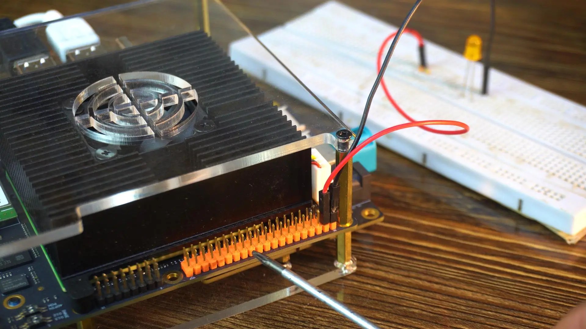
For now, the 40-pin header is more than enough.
And here’s the fun part.
The pin layout is exactly like the RDK X5. So the same settings we used on the RDK X5…
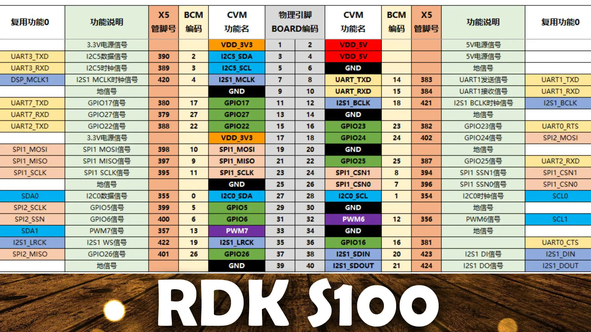
We use the same settings on the RDK S100. So; for the system configuration read my programming article on the RDK X5.
To keep things simple, I will use the same GPIO 37.
D-Robotics has made everything super easy for us. They even included built-in examples;
So you can start very quickly.

As you can see, these examples are more than enough to get started.
But there’s one thing missing.
There is no example for graphical user interface design. And that’s exactly what I am going to cover.
LED interfacing with RDK S100:

Connect the anode leg of the LED to pin 37 through a 330-ohm resistor.
And connect the cathode leg of the LED to pin 39.
RDK S100 Led blinking Python code:
|
1 2 3 4 5 6 7 8 9 10 11 12 13 14 15 16 17 18 19 20 21 22 23 24 25 26 27 28 29 30 31 32 33 34 35 36 37 38 39 40 |
import Hobot.GPIO as GPIO import time # Define the pin you want to use (Physical Pin 37) led_pin = 37 def main(): # 1. Setup the GPIO mode to BOARD (using physical pin numbers) GPIO.setmode(GPIO.BOARD) # 2. Setup the pin as OUTPUT # Note: If you get a warning, the pin might be busy or not cleaned up previously. GPIO.setwarnings(False) GPIO.setup(led_pin, GPIO.OUT) print(f"Starting blink on Pin {led_pin}...") print("Press Ctrl+C or the Stop button to exit.") try: # 3. Loop to blink the LED while True: GPIO.output(led_pin, GPIO.HIGH) # Turn On print("LED ON") time.sleep(1) # Wait 1 second GPIO.output(led_pin, GPIO.LOW) # Turn Off print("LED OFF") time.sleep(1) # Wait 1 second except KeyboardInterrupt: # Handle the stop button or Ctrl+C print("\nStopping...") finally: # 4. Clean up usually resets the ports to a safe state GPIO.cleanup() print("GPIO Cleaned up.") if __name__ == "__main__": main() |
This script is a simple but powerful way to control real hardware using the RDK S100. First, we import the GPIO and time libraries so the system can talk to the pins and handle delays.
We then select physical pin 37 and set the GPIO mode to BOARD, which means we are using the actual pin numbers on the header, not internal names.
Next, we configure this pin as an output, allowing it to control an LED. Inside an infinite loop, the code turns the LED ON, waits for one second, then turns it OFF and waits again, creating a clean blinking effect that runs in real time.
To run this code, simply click on the Play button.

And as you can see, the LED has started blinking.
This confirms that our pin is working, and everything is set up correctly.
Now, let’s go ahead and control this same LED using a graphical user interface “GUI”.
Design the GUI (using Qt Designer) PyQt 5:
First of all, you need to install PyQt5.
I already explained the installation process in my RDK X5 programming video and article.
You just need to follow the same method here.
- Anyway; while the terminal is open, type designer and press enter.
- This will open the Qt Designer tool, which we will use to visually create our GUI.
- In the “New Form” dialog, select Main Window and click Create.
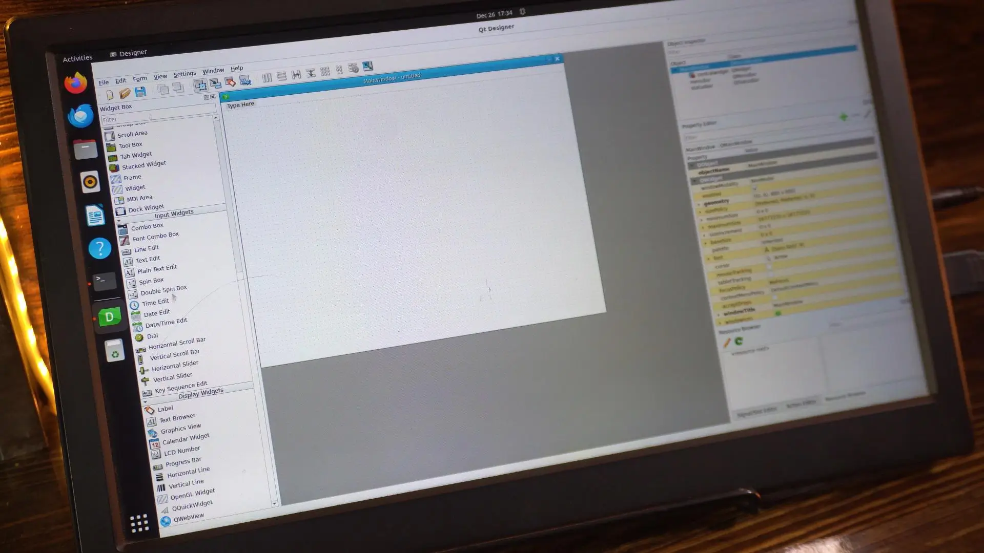
On the left side, you can see we have a lot of widgets available.
You can add anything you need for your project.
Once you use it a little, you will get a clear idea of how this software works. So, I am not going to waste your time by explaining basic things.
I have already written the Python script for you, and I have also designed the GUI.

Python Code for RDK S100 GPIO Control:
|
1 2 3 4 5 6 7 8 9 10 11 12 13 14 15 16 17 18 19 20 21 22 23 24 25 26 27 28 29 30 31 32 33 34 35 36 37 38 39 40 41 42 43 44 45 46 47 48 49 50 51 52 53 54 55 56 57 58 59 60 |
import sys import Hobot.GPIO as GPIO from PyQt5.QtWidgets import QApplication, QMainWindow from PyQt5 import uic # --- HARDWARE SETUP --- # Change this to Pin 37 if that is where your LED is connected LED_PIN = 37 GPIO.setmode(GPIO.BOARD) GPIO.setwarnings(False) GPIO.setup(LED_PIN, GPIO.OUT) class LEDController(QMainWindow): def __init__(self): super().__init__() # Load the UI file you created in Qt Designer try: uic.loadUi('led_control.ui', self) except FileNotFoundError: print("Error: Could not find 'led_control.ui'. Make sure it's in the same folder!") sys.exit(1) # Initialize LED State self.is_led_on = False self.update_hardware() # Connect the button click to our function # 'btn_toggle' must match the objectName you set in Designer self.btn_toggle.clicked.connect(self.toggle_led) def toggle_led(self): # Flip the state self.is_led_on = not self.is_led_on self.update_hardware() def update_hardware(self): if self.is_led_on: GPIO.output(LED_PIN, GPIO.HIGH) # Update the label (lbl_status must match Designer objectName) if hasattr(self, 'lbl_status'): self.lbl_status.setText("LED is ON") self.lbl_status.setStyleSheet("color: green; font-weight: bold;") else: GPIO.output(LED_PIN, GPIO.LOW) if hasattr(self, 'lbl_status'): self.lbl_status.setText("LED is OFF") self.lbl_status.setStyleSheet("color: black;") def closeEvent(self, event): # Clean up GPIO when closing the window GPIO.cleanup() event.accept() if __name__ == "__main__": app = QApplication(sys.argv) window = LEDController() window.show() sys.exit(app.exec_()) |
This Python script links the PyQt5 interface directly with the hardware on the RDK S100. The GUI we design in Qt Designer is saved as a .ui file, and that file is loaded inside the Python code using uic.loadUi.
This means the UI file name must match exactly; for example, if the file is called led_control.ui, the same name must be used in the script, and the file must be in the same folder.
Inside that UI, the object names are just as important: the button must be named btn_toggle and the label must be named lbl_status, because the Python code talks to them using these exact names.
When you click the button, the code toggles the GPIO pin to turn the LED ON or OFF, and at the same time updates the label text and color to show the LED status in real time. If any name is different;
- The .ui file,
- The button, or
- The label
The connection breaks and the program will not work.
Exact naming is what keeps the GUI and the hardware perfectly in sync.
To run this project, it’s very simple. Just click the Play button, and the application will launch the graphical user interface for you.

As soon as the window opens, you will see the button on the screen. When you click that button, the software sends a command to the GPIO pin, and the LED turns ON or OFF instantly.

At the same time, the label in the interface updates in real time, so you always know the current LED status. This is a perfect example of how software, a GUI, and physical hardware work together as one complete system.
You are not just running code; you are controlling real electronics through a clean and simple interface.
And if you want everything ready to use; the complete project folder, the Python script, the PyQt5 UI file, and all required resources; you can download it directly from my Patreon page. That way, you can run the project, study it, and build on top of it yourself.
So; that’s all for now.
FAQs
1. What is the RDK S100, and what makes it different from other AI boards?
The RDK S100 is an edge AI board with 80 TOPS of AI power, capable of running real-time computer vision applications without stressing the CPU, ideal for AI and robotics projects.
2. How do I control GPIO pins on the RDK S100?
You can control GPIO pins directly using Python and the Hobot.GPIO library, either with scripts or through a GUI built with PyQt5.
3. Which GPIO pin should I use for my LED or sensor projects?
In the example, physical pin 37 is used to control an LED. The RDK S100 has a 49-pin header, and the first 40 pins are sufficient for most projects.
4. How do I safely connect LEDs, resistors, or other components to the RDK S100?
Connect the LED anode through a 330-ohm resistor to pin 37 and the cathode to pin 39 to prevent overcurrent and protect the board.
5. How do I create a GUI using Qt Designer for GPIO control?
Open Qt Designer (designer), select Main Window → Create, drag widgets onto the window, and save the .ui file. Object names in the GUI must match the Python code to control hardware.
6. How do I link the GUI button to control a GPIO pin?
Use Python to connect the button click to a function:
|
1 |
self.btn_toggle.clicked.connect(self.toggle_led) |
This toggles the LED when clicked.
7. How do I make an LED blink using the RDK S100 GPIO?
Example Python code:
|
1 2 3 4 5 6 7 |
GPIO.setmode(GPIO.BOARD) GPIO.setup(37, GPIO.OUT) while True: GPIO.output(37, GPIO.HIGH) time.sleep(1) GPIO.output(37, GPIO.LOW) time.sleep(1) |
8. Can the RDK S100 handle AI projects like squats counter or object tracking in real time?
Yes. The board can process high-FPS computer vision tasks, including human pose detection, object tracking, and YOLOv5x object detection, all in real time.
9. How do I update the GUI label to reflect LED status?
Use:
|
1 |
lbl_status.setText("LED is ON") # or "LED is OFF" |
Optionally, change colors with setStyleSheet for visual feedback.
10. How do I clean up GPIO to prevent warnings or conflicts?
Call GPIO.cleanup() at the end of your script or in the GUI’s close event to safely reset the pins.
Watch Video Tutorial:

Discover more from Electronic Clinic
Subscribe to get the latest posts sent to your email.