RDK X5 Programming Tutorial: GPIO Control, GUI Design & Thonny IDE Guide
From GPIO Basics to GUI Control: A Practical RDK X5 Python Guide
Last Updated on December 14, 2025 by Engr. Shahzada Fahad
Table of Contents
D-Robotics RDK X5:
If you just unboxed your RDK X5 and are looking for a complete RDK X5 programming tutorial, then this article is exactly for you. You might be wondering how to actually use it… how to control a single pin… how to design a simple GUI… or how to edit its code inside Thonny IDE.
In my previous article, I unboxed the RDK X5, went through all the components, and showed you how to install the operating system and get everything running.
Today, I am not repeating any of that.
This time, Meshonology sent me another RDK X5 so I can make a complete, practical tutorial on:
- How to use the RDK X5
- How to control a specific pin
- How to design a basic graphical user interface
- How to use the Thonny IDE
- And how to edit or modify existing code
Huge thanks to Meshnology! After my amazing experience with their Heltec LoRa 32 (N35) kit, I highly recommend visiting their website to check out their impressive range of development tools.
Many of the concepts used in this RDK X5 programming tutorial, such as GPIO control, GUI design, and Thonny IDE usage, are similar to Raspberry Pi workflows.
You can also explore our detailed Raspberry Pi GPIO Control, GUI Design & Thonny IDE Guide
Amazon Links:
Other Tools and Components:
ESP32 WiFi + Bluetooth Module (Recommended)
Arduino Nano USB C type (Recommended)
*Please Note: These are affiliate links. I may make a commission if you buy the components through these links. I would appreciate your support in this way!
After reading this article, you will clearly understand how to control anything on the RDK X5.
And once you learn how to control even a single GPIO pin, you can expand this knowledge to control almost anything.
So stay tuned, and don’t skip. Read it completely; it’s simple, beginner-friendly, and step-by-step.
About the OS “Operating System”:
This time, I am using this “rdk_os_3.3.3-2025-9-28” operating system.
The method of flashing the operating system onto the SD card is exactly the same, and I already explained that step-by-step in my getting started tutorial on the RDK X5.
RDK X5 Pinout Chart:
Now before we start controlling any GPIO pin, let me show you this chart.
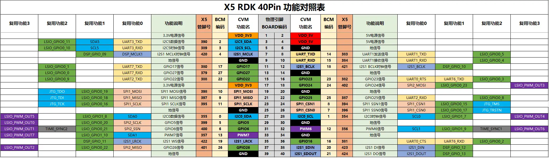
This is the official RDK X5 40-pin header pinout, and trust me… you will be using this a lot.
At first glance, it looks big and a little complicated, but don’t worry; it’s actually very simple once you understand the layout.
Every row here represents a pin on the 40-pin header, and each column shows what that pin can do.
Some pins support multiple functions, like UART, I²C, SPI, PWM, or general GPIO.
And some pins are power pins; like 5V, 3.3V and ground.
But for this article, we will focus on the GPIO pins, because once you learn how to control even one GPIO pin, you can control LEDs, relays, sensors, motors; basically anything.
So whenever you are working on a project, just check this chart, find the pin number, and see what functions it supports.
We will keep things simple, and I will show you exactly which pin we are going to use and why.
Alright… let’s move to the practical part.
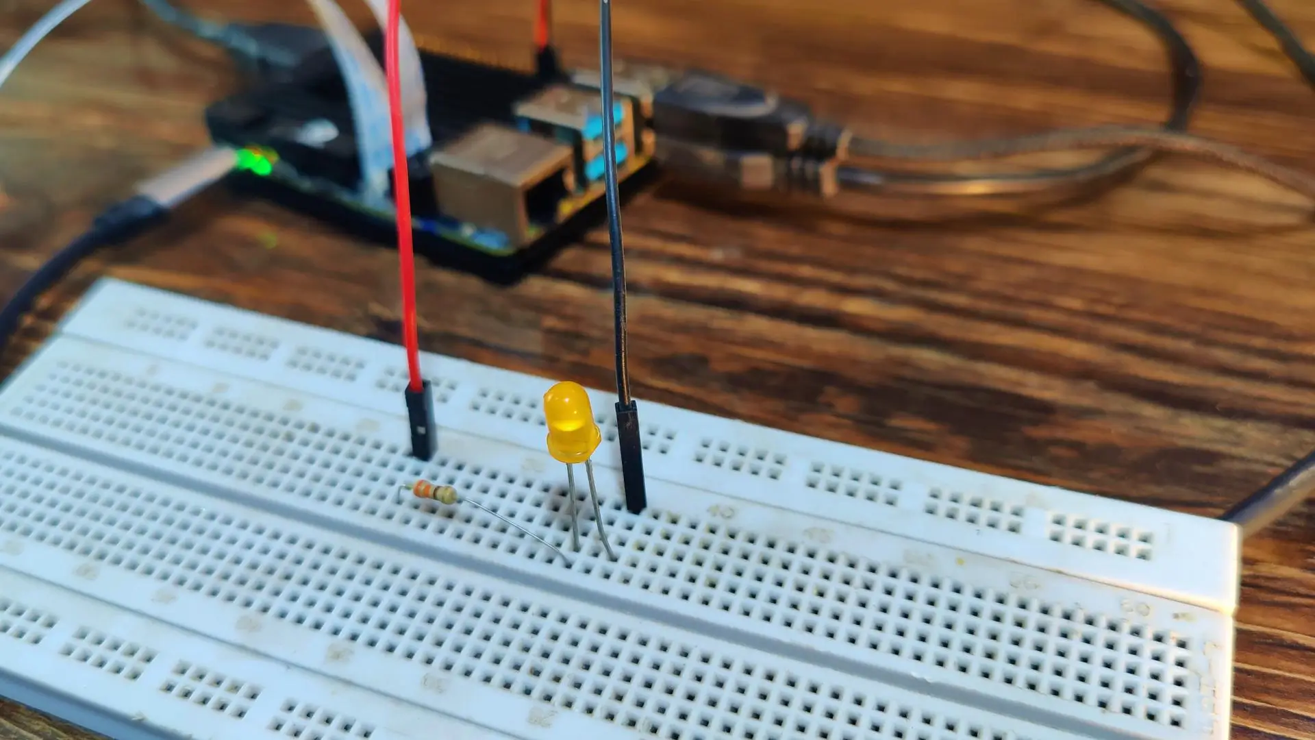
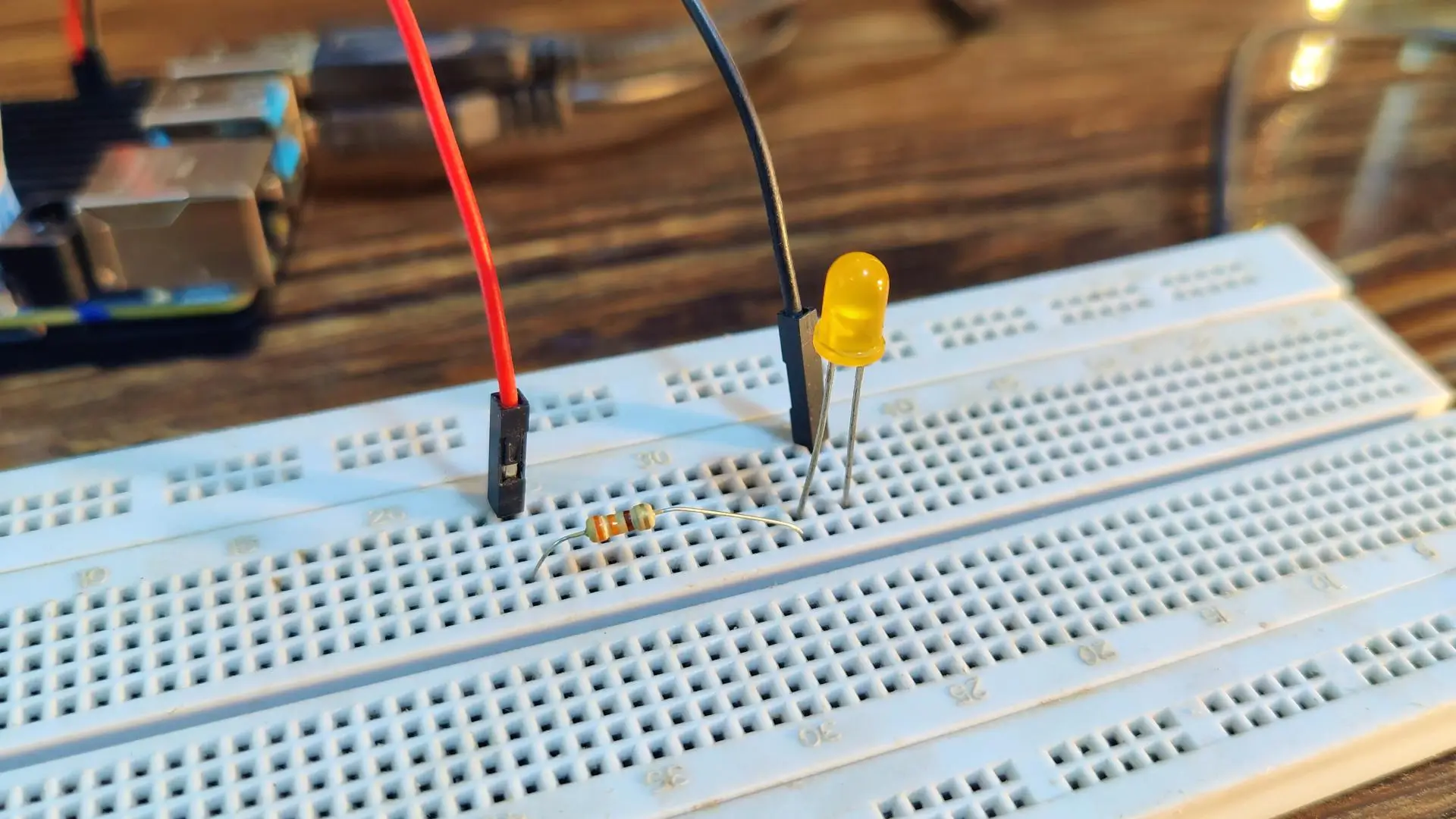
LED Connections:
I have connected an LED to pin number 37.
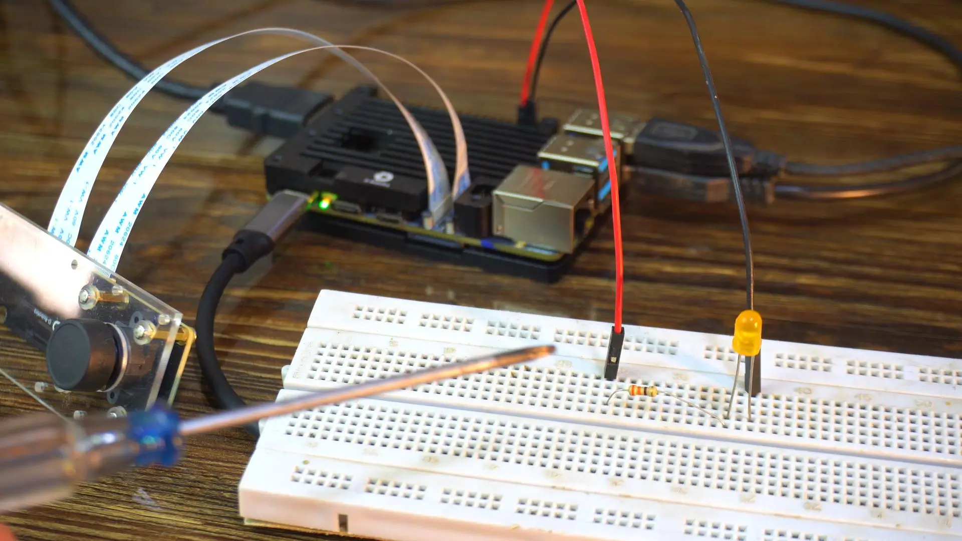
For now, I am starting with the LED because it’s simple and we can instantly see the result.
Once this works, you can replace it with a high-power load using the appropriate driver circuit.
System Configuration (srpi-config)
In the RDK X5 40-pin diagram, pin 37 is mapped to GPIO26.
But it also has another function; it can work as SPI2_MISO.
So before we use this pin as a normal GPIO, we need to make sure it’s not configured for a special function like SPI, I²C, or PWM. If a pin is already in a special mode, it won’t behave like a regular GPIO.
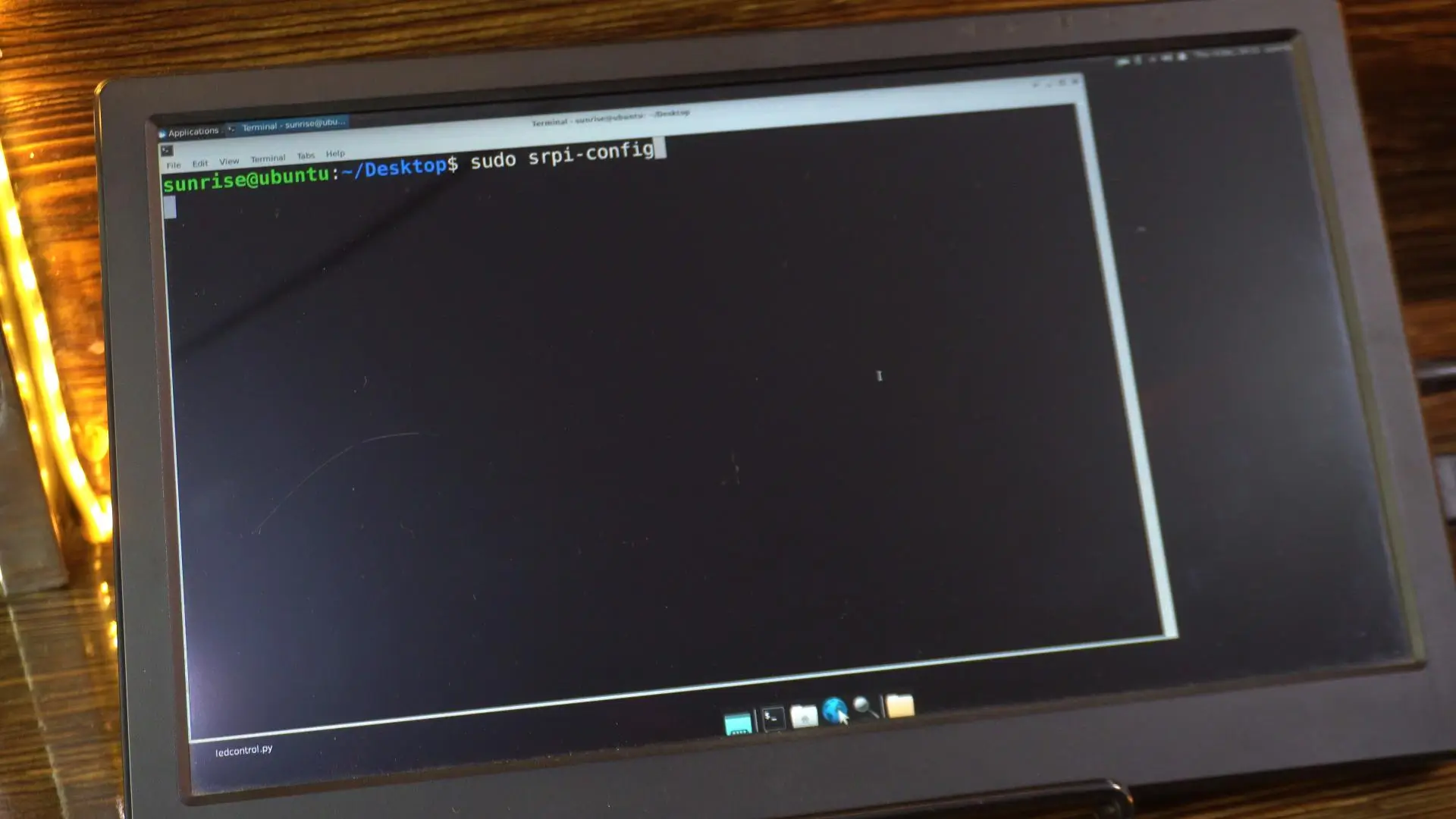
To confirm this, open the terminal on your RDK X5.
Simply right-click anywhere on the desktop and select “Open Terminal Here”
Now type this command:
|
1 |
sudo srpi-config |
Navigate to 3 Interface Options
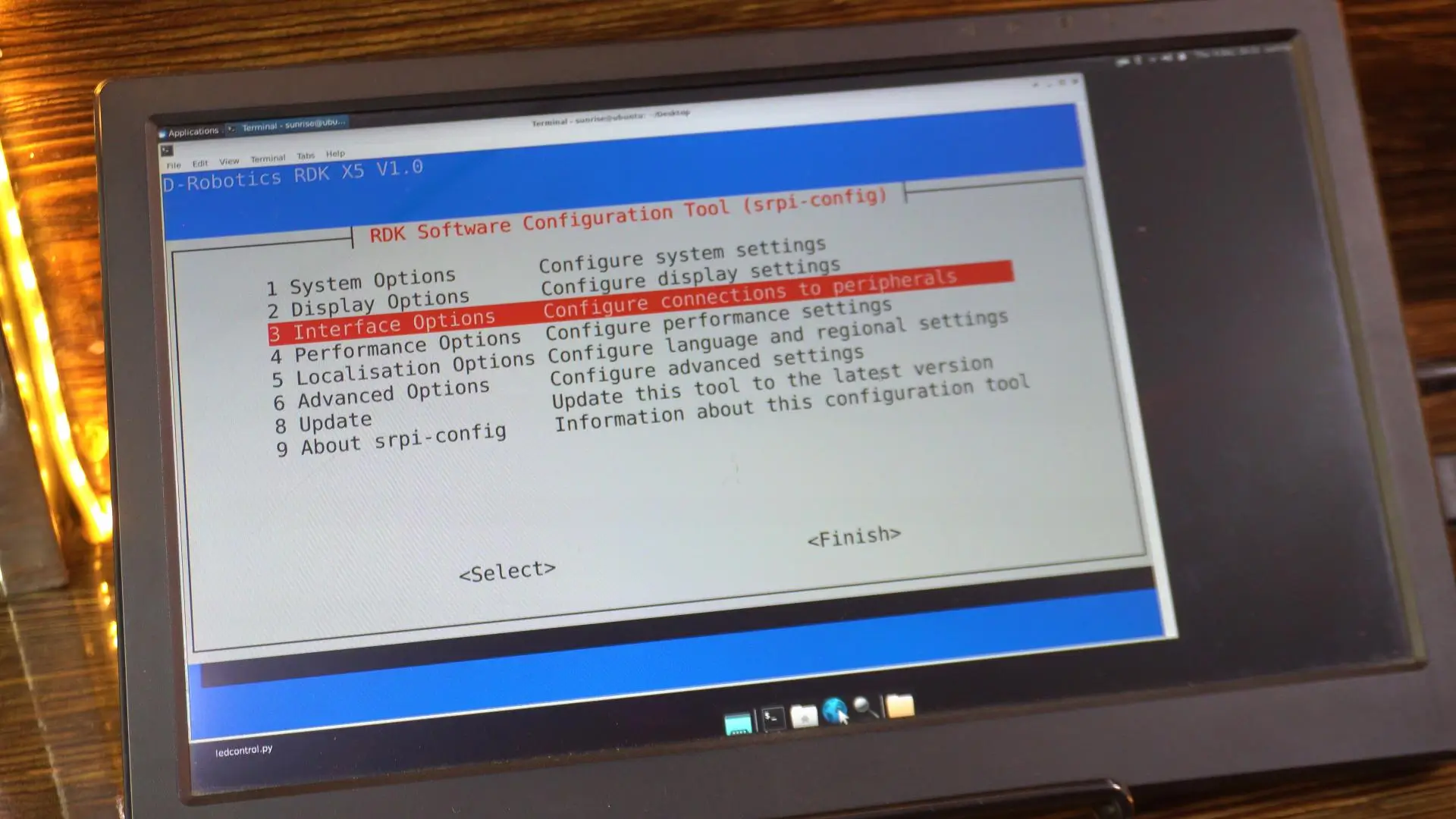
And then select “I3 Peripheral bus config”.
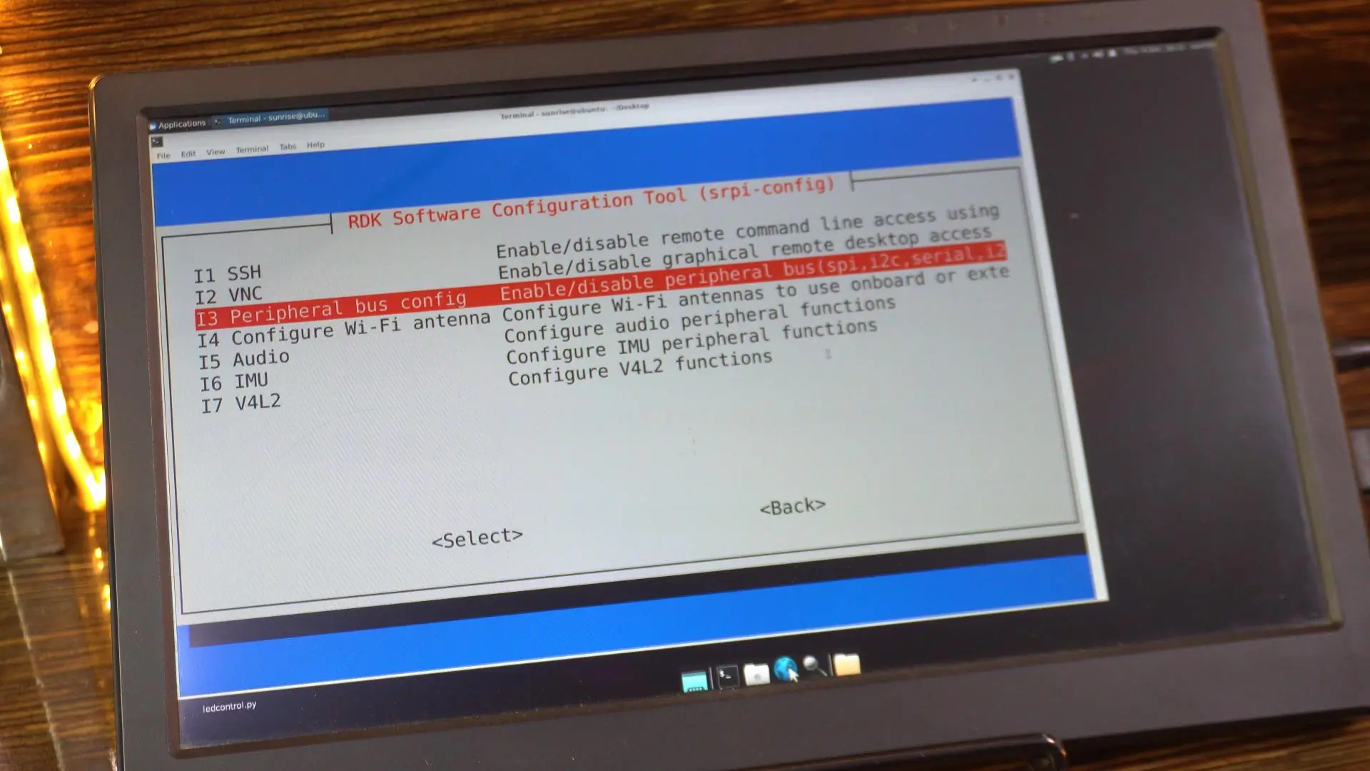
Ensure the pin you want to use is NOT enabled for a special function (like PWM or SPI). You can see SPI2 is disabled.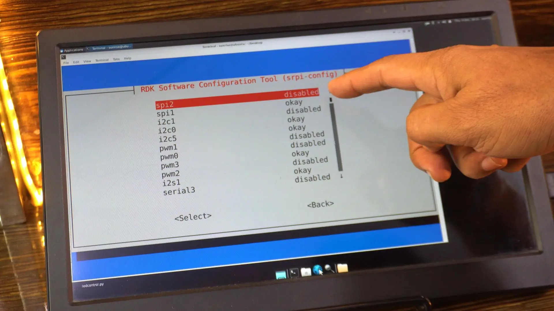
If all special functions for a pin group are “disabled”, the pins default to standard GPIO mode.
If you changed anything, reboot the board (sudo reboot).
Check Pre-installed Examples
The RDK X5 usually comes with example code pre-installed. You can find them here:
|
1 |
cd /app/40pin_samples/ |
Next command
|
1 |
ls |
You should see a file named simple_out.py.
To run it, simply type:
|
1 |
sudo python3 simple_out.py |
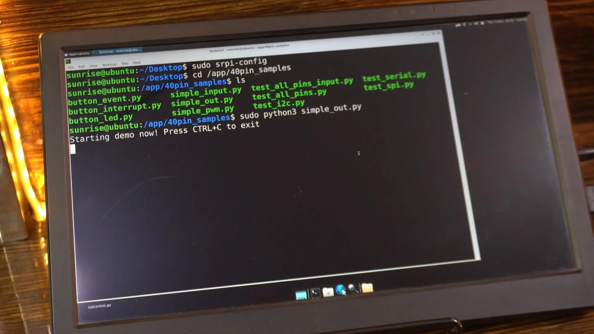
And as you can see, the LED has started blinking.
This confirms that our pin is working, and everything is set up correctly.
If you want to open the file and make any changes, you can do that as well.
Just run this command in your terminal:
|
1 |
sudo nano simple_out.py |
Inside the code, you will clearly see that pin 37 is being used.
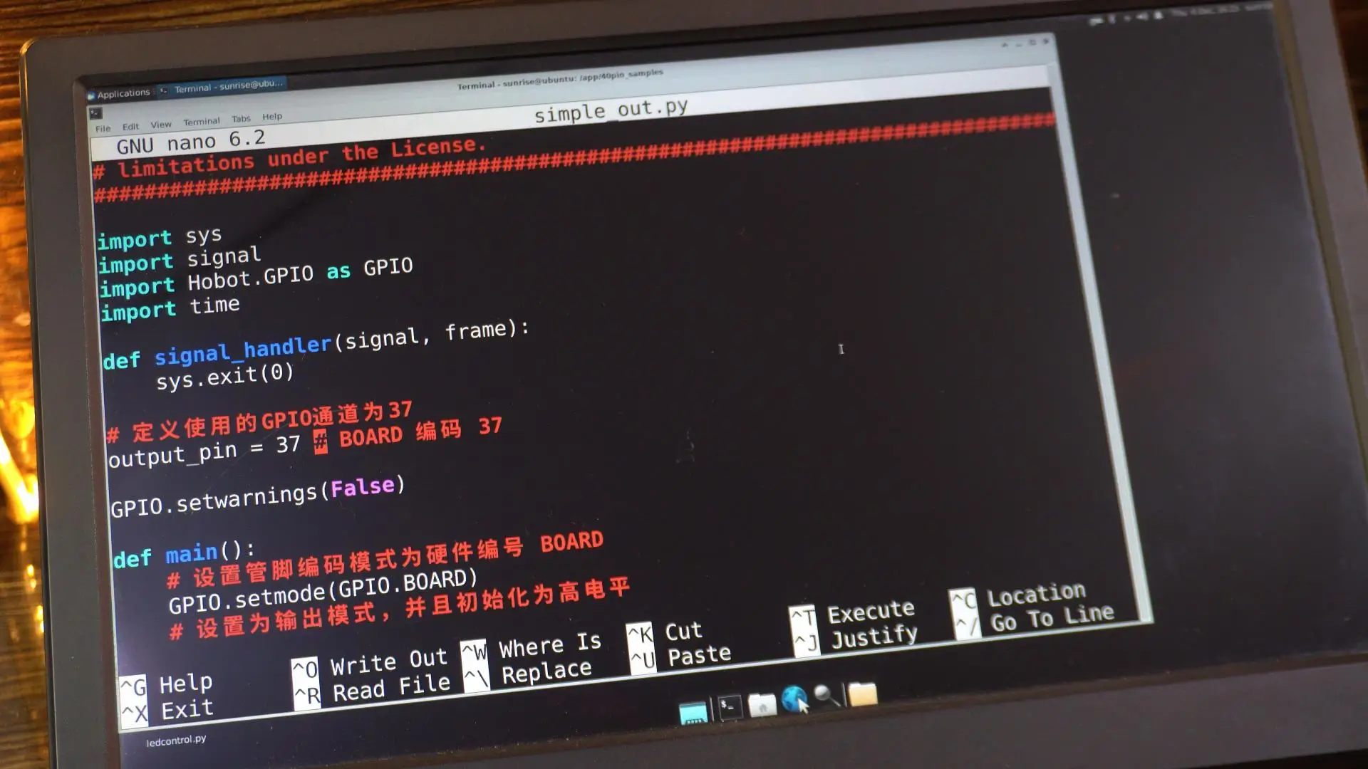
You can modify anything you want in this file; adjust the delay, change the pin number, or add more functionality.
It’s completely up to you.
And if you prefer, you can open this same code directly in the Thonny IDE and edit it there.
Thonny makes it easier to write, test, and save your Python scripts.
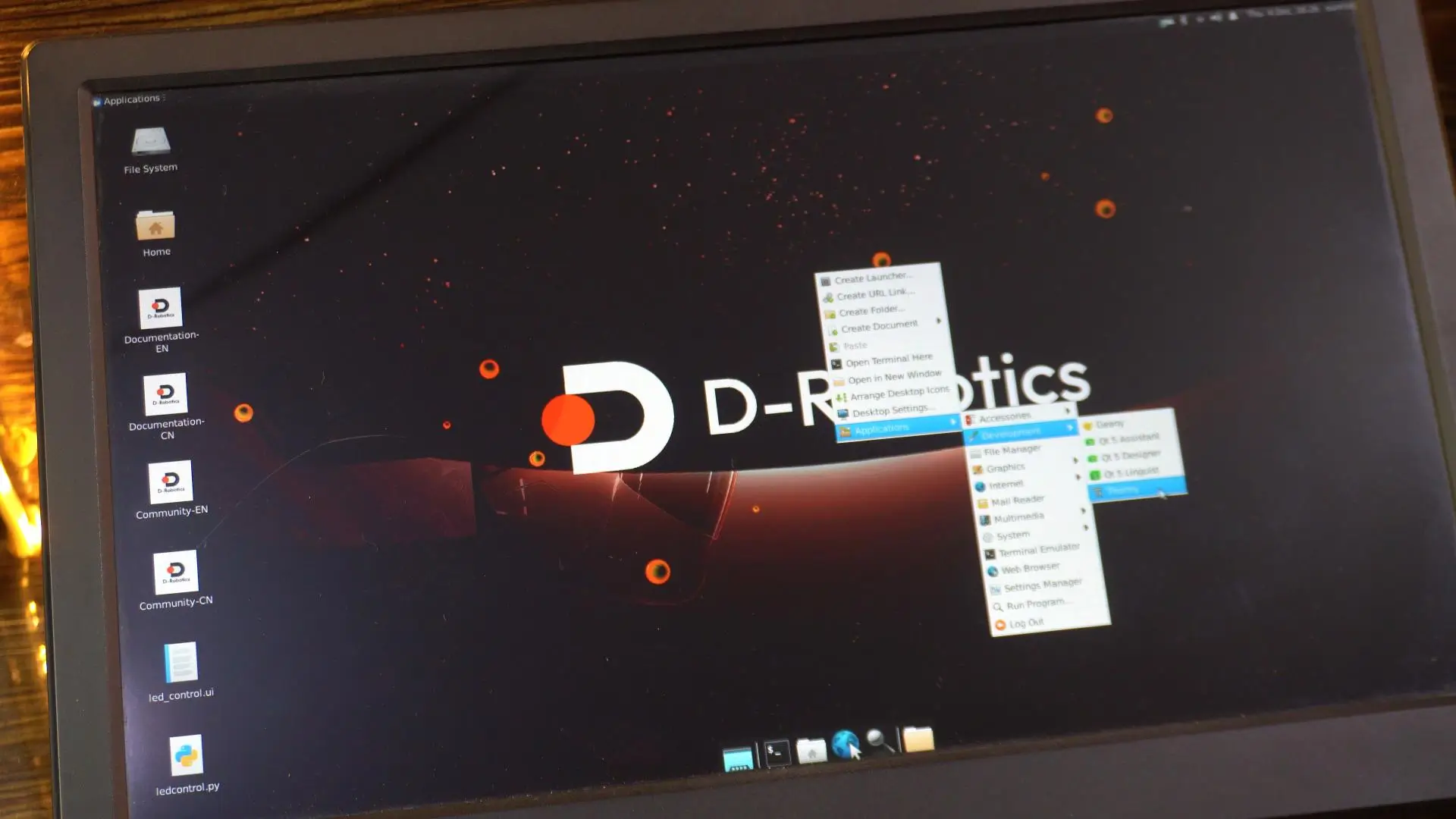
While you are on the desktop, simply right-click, go to Applications, then Development, and click on Thonny IDE.
Once Thonny opens, click on the Open button.
Now click on Other locations.
Select Computer.
Open the app directory.
Here you will see the 40pin_samples folder; open this folder.

And now you can see all the example files right here.
You can open any of them, modify them, save them, or create your own script based on these examples.
Let’s open and run the same simple_out.py example.
Once you open the file in Thonny IDE, making changes becomes very easy.
You can edit the pin number, adjust the timing, or add print statements; whatever you need.
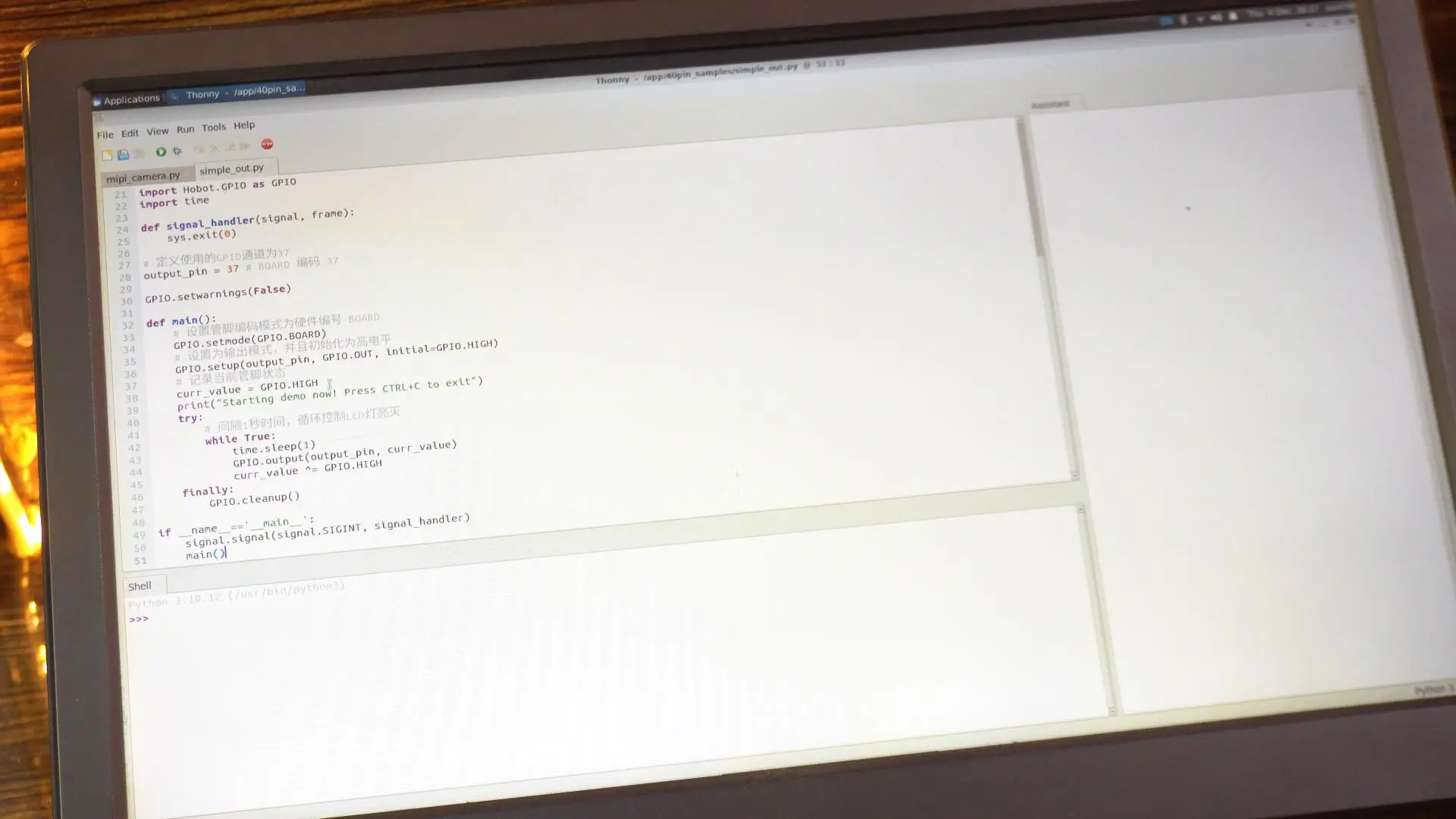
Anyway, let’s go ahead and run this code.
The LED started blinking.
I have also written my own version of this script, where I added print messages for LED ON and LED OFF.
RDK X5 LED Blinking Code:
|
1 2 3 4 5 6 7 8 9 10 11 12 13 14 15 16 17 18 19 20 21 22 23 24 25 26 27 28 29 30 31 32 33 34 35 36 37 38 39 40 |
import Hobot.GPIO as GPIO import time # Define the pin you want to use (Physical Pin 37) led_pin = 37 def main(): # 1. Setup the GPIO mode to BOARD (using physical pin numbers) GPIO.setmode(GPIO.BOARD) # 2. Setup the pin as OUTPUT # Note: If you get a warning, the pin might be busy or not cleaned up previously. GPIO.setwarnings(False) GPIO.setup(led_pin, GPIO.OUT) print(f"Starting blink on Pin {led_pin}...") print("Press Ctrl+C or the Stop button to exit.") try: # 3. Loop to blink the LED while True: GPIO.output(led_pin, GPIO.HIGH) # Turn On print("LED ON") time.sleep(1) # Wait 1 second GPIO.output(led_pin, GPIO.LOW) # Turn Off print("LED OFF") time.sleep(1) # Wait 1 second except KeyboardInterrupt: # Handle the stop button or Ctrl+C print("\nStopping...") finally: # 4. Clean up usually resets the ports to a safe state GPIO.cleanup() print("GPIO Cleaned up.") if __name__ == "__main__": main() |
So let’s run that code as well and see the output.

Design the GUI (using Qt Designer) Qt 5:
Now, let’s take this to another level and design a GUI for it.
To do that, we first need to install PyQt5, and the recommended way on the RDK X5 is to install it directly through apt.
This method is the most stable and works perfectly.
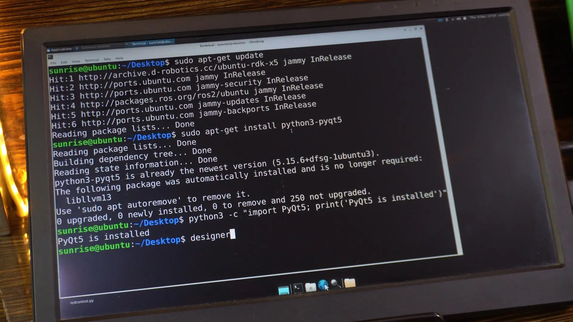
Open your terminal and run the following commands:
|
1 2 3 |
sudo apt-get update sudo apt-get install python3-pyqt5 |
This will install everything needed for building a basic graphical interface on the RDK X5.
Verify Installation
To check if PyQt5 was installed successfully, you can run a quick one-line import test.
|
1 |
python3 -c "import PyQt5; print('PyQt5 is installed')" |
Great! You can see it printed “PyQt5 is installed.” You can see in the image above.
That means everything is working perfectly.
Now type:
Designer
And press Enter.
This will open the Qt Designer tool, which we will use to visually create our GUI.
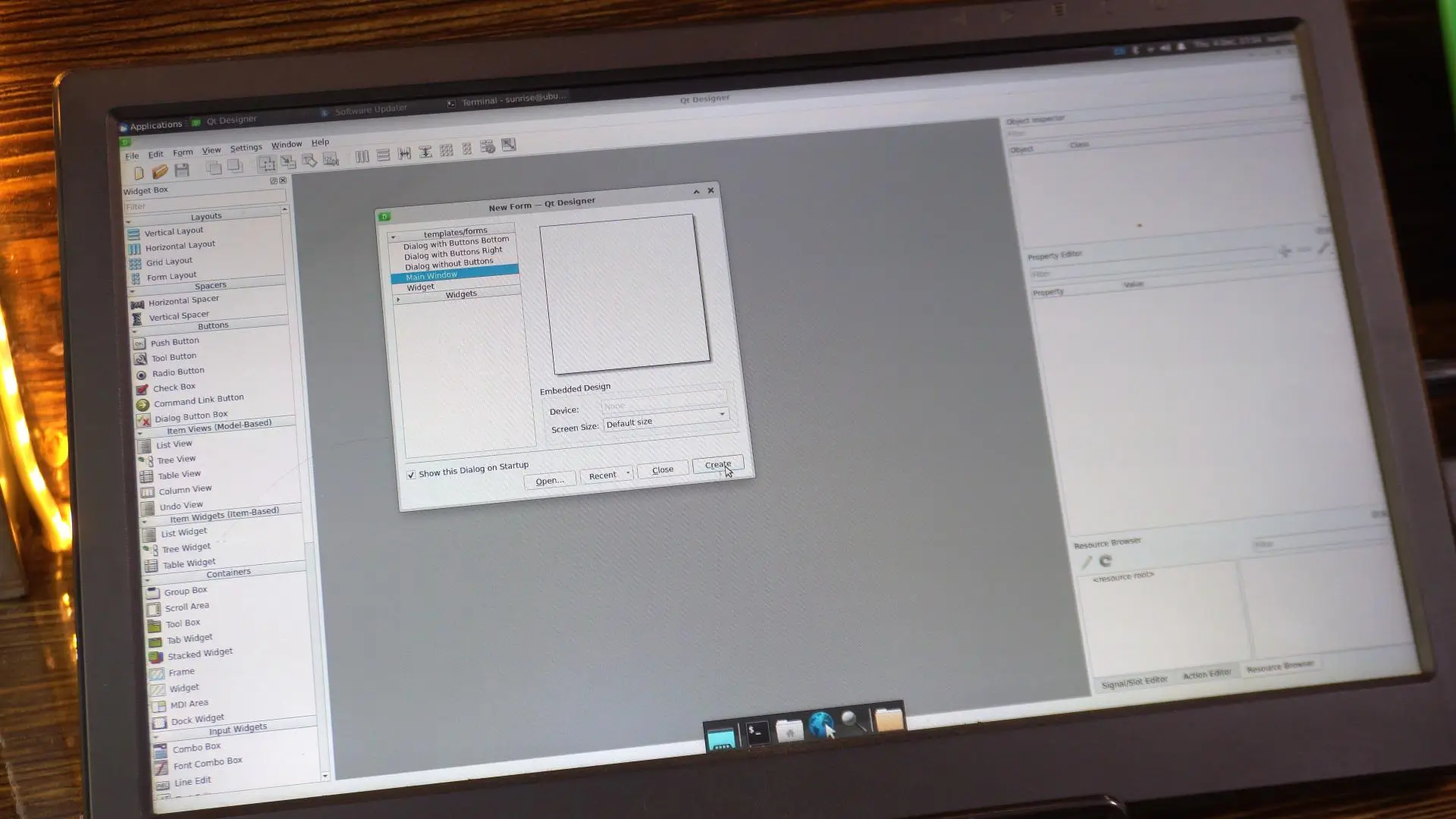
In the “New Form” dialog, select Main Window and click Create.
On the left side, you can see we have a lot of widgets available.
You can add anything you need for your project.
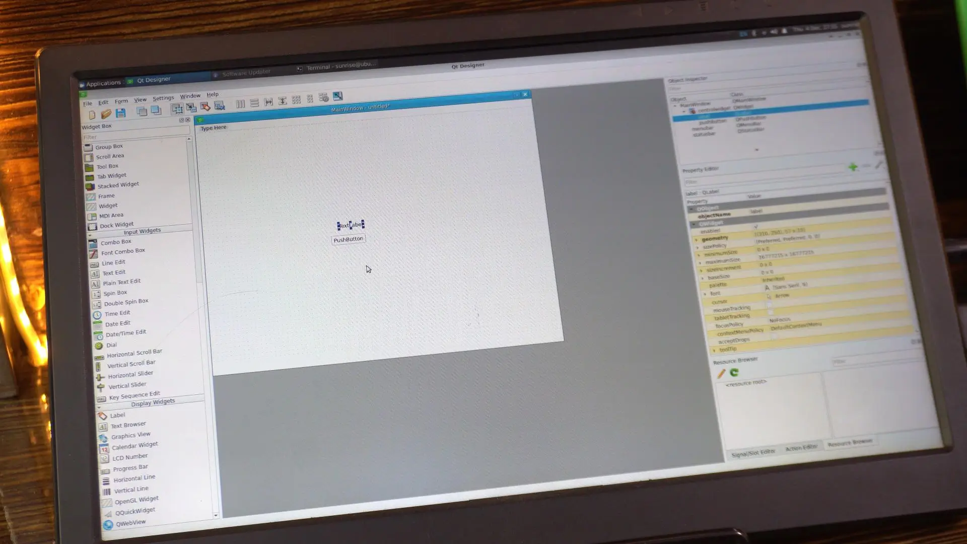
For my LED control, I only need one Push Button and one Label, so I can update the LED status on the screen.
I have already created the user interface, so let me quickly open it.
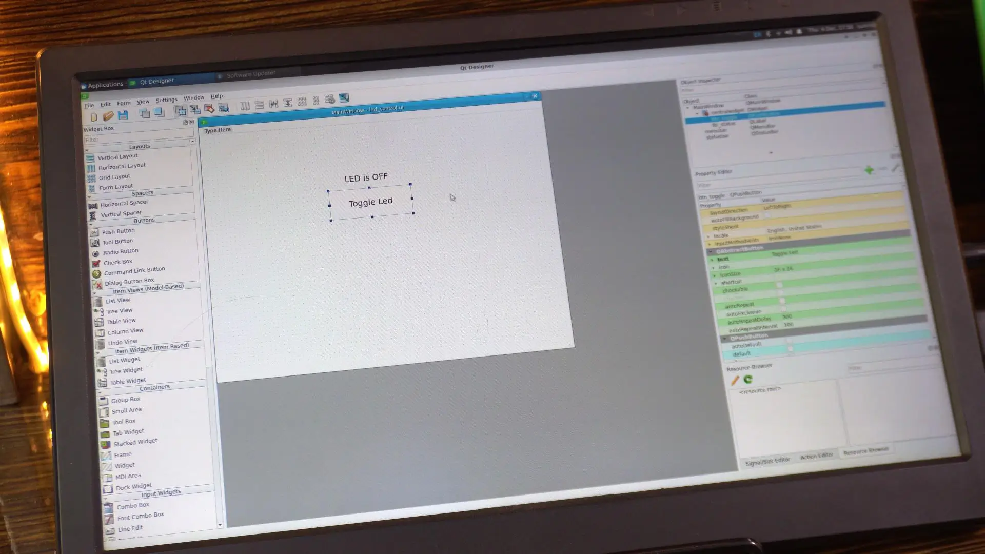
As you can see, I have added one label and one button.
For the button; I set the objectName to btn_toggle.
And I changed the button text to “Toggle LED”.
Now similarly, for the label:
I set the objectName to lbl_status.
And the text is set to “LED is OFF.”
Once your design is complete, go ahead and save the project.
I have saved it with the name led_control.ui.
I have also written the Python code to load this led_control.ui file and control the LED.
Copy and paste the following code in Thonny IDE.
|
1 2 3 4 5 6 7 8 9 10 11 12 13 14 15 16 17 18 19 20 21 22 23 24 25 26 27 28 29 30 31 32 33 34 35 36 37 38 39 40 41 42 43 44 45 46 47 48 49 50 51 52 53 54 55 56 57 58 59 60 |
import sys import Hobot.GPIO as GPIO from PyQt5.QtWidgets import QApplication, QMainWindow from PyQt5 import uic # --- HARDWARE SETUP --- # Change this to Pin 37 if that is where your LED is connected LED_PIN = 32 GPIO.setmode(GPIO.BOARD) GPIO.setwarnings(False) GPIO.setup(LED_PIN, GPIO.OUT) class LEDController(QMainWindow): def __init__(self): super().__init__() # Load the UI file you created in Qt Designer try: uic.loadUi('led_control.ui', self) except FileNotFoundError: print("Error: Could not find 'led_control.ui'. Make sure it's in the same folder!") sys.exit(1) # Initialize LED State self.is_led_on = False self.update_hardware() # Connect the button click to our function # 'btn_toggle' must match the objectName you set in Designer self.btn_toggle.clicked.connect(self.toggle_led) def toggle_led(self): # Flip the state self.is_led_on = not self.is_led_on self.update_hardware() def update_hardware(self): if self.is_led_on: GPIO.output(LED_PIN, GPIO.HIGH) # Update the label (lbl_status must match Designer objectName) if hasattr(self, 'lbl_status'): self.lbl_status.setText("LED is ON") self.lbl_status.setStyleSheet("color: green; font-weight: bold;") else: GPIO.output(LED_PIN, GPIO.LOW) if hasattr(self, 'lbl_status'): self.lbl_status.setText("LED is OFF") self.lbl_status.setStyleSheet("color: black;") def closeEvent(self, event): # Clean up GPIO when closing the window GPIO.cleanup() event.accept() if __name__ == "__main__": app = QApplication(sys.argv) window = LEDController() window.show() sys.exit(app.exec_()) |
Let’s run this script.
Practical Demonstration:
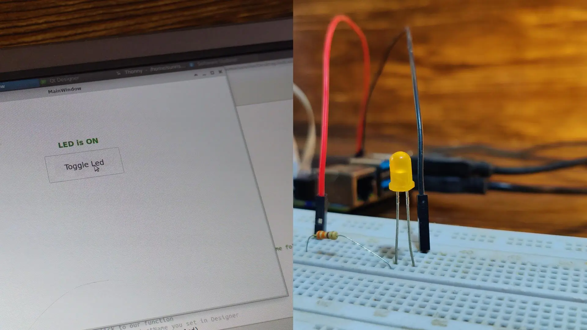
As you can see, we can now control the LED through this button; and at the same time, we can also monitor the LED status right here on the screen. You can easily replace this LED with a MOSFET or a relay to control high-amp DC or even AC loads. I only used a single button in this demo, but you can add multiple buttons to control multiple loads without any issues.
So, that’s all for now.
Watch Video Tutorial:
Related Tutorial Videos:

Discover more from Electronic Clinic
Subscribe to get the latest posts sent to your email.