ESP32S3 Custom Board Build – Unique Features Inside!
A Step-by-Step Tutorial from Schematic Design and PCB Layout to Final Assembly
Last Updated on August 20, 2025 by Engr. Shahzada Fahad
Table of Contents
ESP32S3 Custom Development Board:
ESP32S3 Custom Board Build – Unique Features Inside!- You have seen tons of ESP32 development boards, but none like this one…

After years of testing and using every popular ESP32 board out there; I finally designed my own… and honestly, it’s the most powerful and practical board I have ever used.
I am talking about my custom ESP32-S3 development board; built not just for raw performance, but for real-world projects.
Every ESP32 board I have used had something missing.

Some didn’t support batteries. Others supported batteries but couldn’t handle high-current loads. Some lacked a USB-C port. Some had an OLED display, and others didn’t.
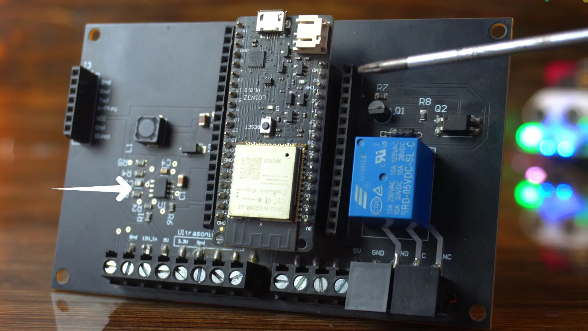
You may have seen this older development board in many of my previous ESP32-based projects.

It was designed specifically for beginners. I used a 7805 voltage regulator; which is okay for basic experiments, but when it comes to building actual products, it just doesn’t hold up.
The main issue was power. The 7805 can only provide up to 1 amp, and that too only if you use a good heatsink.
It wasn’t powerful enough to run the ESP32 along with multiple sensors or servo motors. Plus, it had limited GPIO pins.
So I upgraded to this second board.
I replaced the older ESP32 Dev Module with a newer one that allowed me to connect a battery, had more GPIOs, and came with a much more powerful power supply; this one could handle up to 3 amps.
I have already written quite a detailed article about this ESP32 Development board; and it worked great. No complaints. I will definitely continue using it in some of my projects.
But now; I have officially moved on to my latest and most advanced development board; and it’s an absolute game-changer.

This board has everything: a USB-C port, support for up to 28 volts input, and you can even connect a solar panel directly. It includes a 5V 3A power supply for high-current devices like servos and sensors, and a separate 3.3V regulator as well.
Battery charging is smart too; when the battery is fully charged, it disconnects automatically to avoid overcharging.
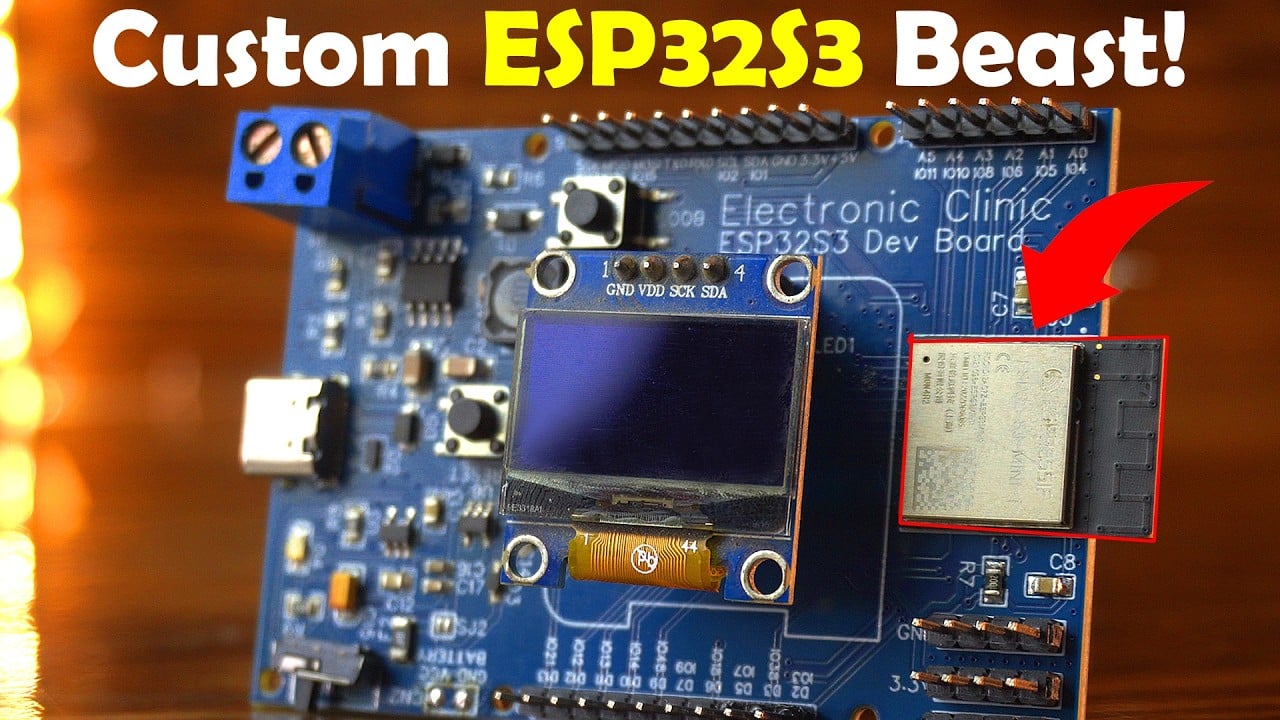
Since I use this as a development board, I have added male headers to most of the GPIOs. I have also added SSD1306 OLED display for quick debugging and status updates.

And most importantly, I have used the ESP32-S3-MINI-1 module. It’s super compact; but don’t be fooled by its size. Performance-wise, it’s an absolute beast.
The ESP32-S3-MINI-1 is a powerful, compact, Wi-Fi + Bluetooth LE module from Espressif, designed specifically for small-size embedded applications. Here’s what’s special about it:
Key Features of ESP32-S3-MINI-1:
- Compact Size with High Performance
Only 13.2mm × 16.6mm; perfect for compact PCB designs;
Based on the ESP32-S3 SoC (dual-core Xtensa LX7, up to 240MHz)
- AI Acceleration Built-In
Supports vector instructions for AI/ML workloads.
Ideal for gesture recognition, speech processing, and sensor fusion
- Dual Wireless: Wi-Fi + Bluetooth 5 (LE)
2.4 GHz Wi-Fi (802.11 b/g/n)
Bluetooth 5 LE with long-range support and LE Audio ready
- Low Power for Battery-Powered Devices
Advanced low-power modes for efficient energy usage.
Ideal for IoT sensors, wearables, and portable devices
- Rich Peripheral Support
43 programmable GPIOs (via the S3 chip)
USB-OTG support (direct USB without extra chip)
SPI, I2C, UART, ADC, DAC, PWM, SD/MMC, LCD interface, etc.
- Integrated Flash (Optional)
Available in variants with 4MB or 8MB Flash
No need for external SPI Flash in many applications
Why Use ESP32-S3-MINI-1 in Your Custom Board?
- Ideal for custom development boards where space saving + performance is needed.
- Direct soldering onto the PCB; no need for additional components.
- Great for DIY electronics, smart displays, UWB + BLE projects, and AIoT systems.

This board is now my go-to template. I use it as a base for all my projects, and then I tweak the schematic based on what I need.
Let’s say I don’t need the OLED display in a specific project; I just remove it, rearrange the components, and adjust the PCB layout. I have full control over the board’s size and design.
If I shift some components to the bottom side, the board gets even smaller. But since I use this mainly for development, I have intentionally kept the size a bit larger.
You can download the schematic, PCB layout, Gerber files, BOM, pick-and-place files, PDF, and example codes; all from my Patreon page.
Now, let’s walk through the schematic, PCB layout, and how to identify and fix common issues in your PCB design.
Amazon Links:
A02YYUW Waterproof Ultrasonic Sensor
DS18b20 Waterproof Temperature Sensor
Other Tools and Components:
ESP32 WiFi + Bluetooth Module (Recommended)
Arduino Nano USB C type (Recommended)
*Please Note: These are affiliate links. I may make a commission if you buy the components through these links. I would appreciate your support in this way!
ESP32S3 Custom Board Diagram / Schematic:
5V 3A power supply Section:

This is the same 5V 3A power supply that I have used on some of my previous development board and also on my custom Arduino Nano development board.
In fact, I have written an entire article just on this power supply; including the complete circuit diagram, step-by-step soldering tutorial, and full testing at the end.
I used this power supply to charge a smartphone, power a microwave motion sensor, run an ESP32 development board, and even supply power to a Raspberry Pi, 5V white LEDs, and DC motors.
So yes; this 5V 3A power supply is already fully tested and explained in depth.
MCP73831 Charging Section:

The MCP73831 is a highly efficient linear battery charging controller, perfect for space-limited and cost-sensitive projects; like DIY development boards and wearable gadgets.
It’s designed specifically for single-cell Li-Ion and Li-Po batteries, and it works by using a constant-current/constant-voltage (CC/CV) charging method.
This little chip; the MCP73831; handles Li-Ion and Li-Po battery charging with great precision.
It has built-in current sensing, reverse discharge protection, and thermal regulation.
Fixed and accurate voltage regulation at ±0.75%, with options like 4.20V, 4.35V, 4.40V, 4.50V, and programmable charging current from 15mA up to 500mA.
Once the battery is full, it automatically stops charging. And yes, you can even monitor charging status through a simple LED.
Where is it used?
You will find the MCP73831 in:
- Bluetooth headsets
- MP3 players
- USB chargers
- Digital cameras
- And of course, in DIY boards and battery-powered ESP32 projects
How It Works in Your Circuit:
- 5V from the power supply enters the VBUS pin.
- It charges a 3.7V Li-Po battery through the VBAT pin.
- The PROG pin sets the charging current (via a resistor).
- An LED connected to the STAT pin shows charging status.
- The battery powers your ESP32 system via the 3.3V regulator.
Now, you might be wondering how I selected all these components. Well, let me tell you; it’s not random at all! This is actually the typical application circuit straight from the datasheet.
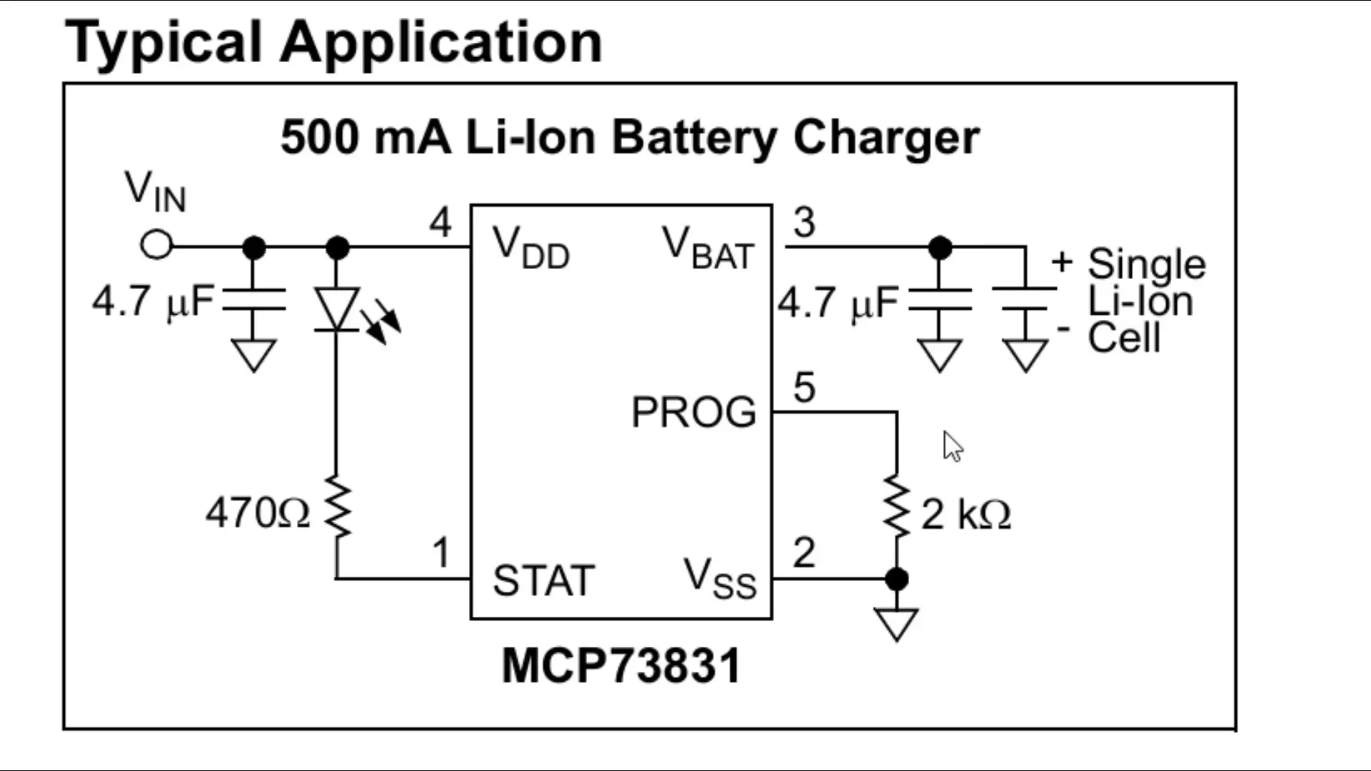
So yes, I have used exactly the same circuit as recommended; no guesswork involved!
Note:
If you need higher charging current, you can replace it with LTC4054; it supports up to 800mA.
3.3V Voltage Regulation Section:
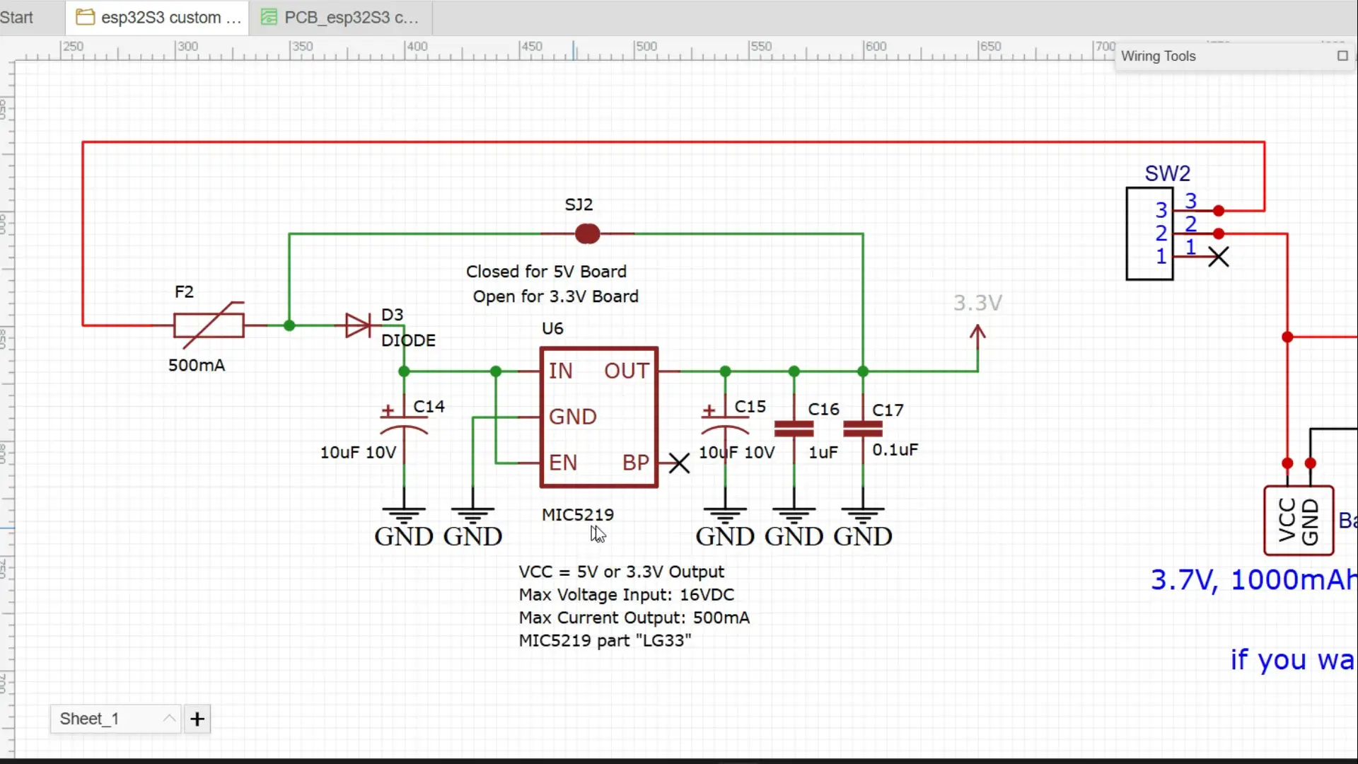
What you are seeing here is a super simple but reliable 3.3V regulator circuit, and it’s based on the MIC5219.
What makes the MIC5219 so good?
Delivers up to 500mA output current; more than enough for powering ESP32, sensors, and other 3.3V modules.
Ultra-low dropout voltage; just 500mV max at full load, so even if your input drops a little, your 3.3V stays stable.
Reverse battery protection, thermal shutdown, and current limiting; it’s built like a tank.
Very low noise output, perfect for analog sensors and RF circuits.
Can be turned ON/OFF via a logic pin, and in shutdown mode, it draws almost no current; great for battery-powered projects.
Here’s how it works:
Battery voltage goes through a fuse and protection diode to guard against overcurrent and reverse polarity.
The MIC5219 drops this to a stable 3.3V output; perfect for low-power devices.
The SJ2 jumper lets you switch between 5V and 3.3V board configurations.
Filter capacitors clean the power and reduce noise.
EN pin keeps the regulator always ON, and BP pin is not used.
It can handle up to 16V input, output 500mA, and is ideal for microcontrollers and sensors.
If you want more details, study the MIC5219 datasheet; it covers everything in depth.
USB-C with ESD protection Section:

This is a USB Type-C 16-pin port.
The data lines USB_P (DP1, DP2) and USB_N (DN1, DN2) are connected to handle high-speed USB communication.
Pins CC1/CC2 and SBU1/SBU2 are unused here, which is common for basic USB 2.0 setups.
D2 (D3V3XA4B10LP-7) this is an ESD protection chip designed to protect sensitive USB data and power lines from electrostatic discharge (ESD).
It protects VBUS, USB_N, and USB_P lines on both sides.
It connects inline with the data lines and power, ensuring any spikes or static discharges don’t fry your main components.
Why It Matters:
USB-C is powerful — it can deliver a lot of current and fast data, but it’s also a point of vulnerability if left unprotected.
This circuit gives you clean data signals and safe power input, without risking your microcontroller, ESP32, or Raspberry Pi.
With ESD protection in place, your board is safe to plug/unplug even in harsh environments.
Additional Components & PCB Design Process
Besides everything else, I have also connected an SSD1306 OLED display to the ESP32-S3 using the SCL and SDA pins.
I have used male/female headers; you can customize these as you like. Many GPIOs are still free, giving you plenty of room for future expansion.

On the ESP32-S3 side, I have also added decoupling capacitors, a reset button, a boot button, and connected all ground pins together for stable operation.
You can download the original circuit diagram from my Patreon page along with all the other resources.
PCB Design & Assembly
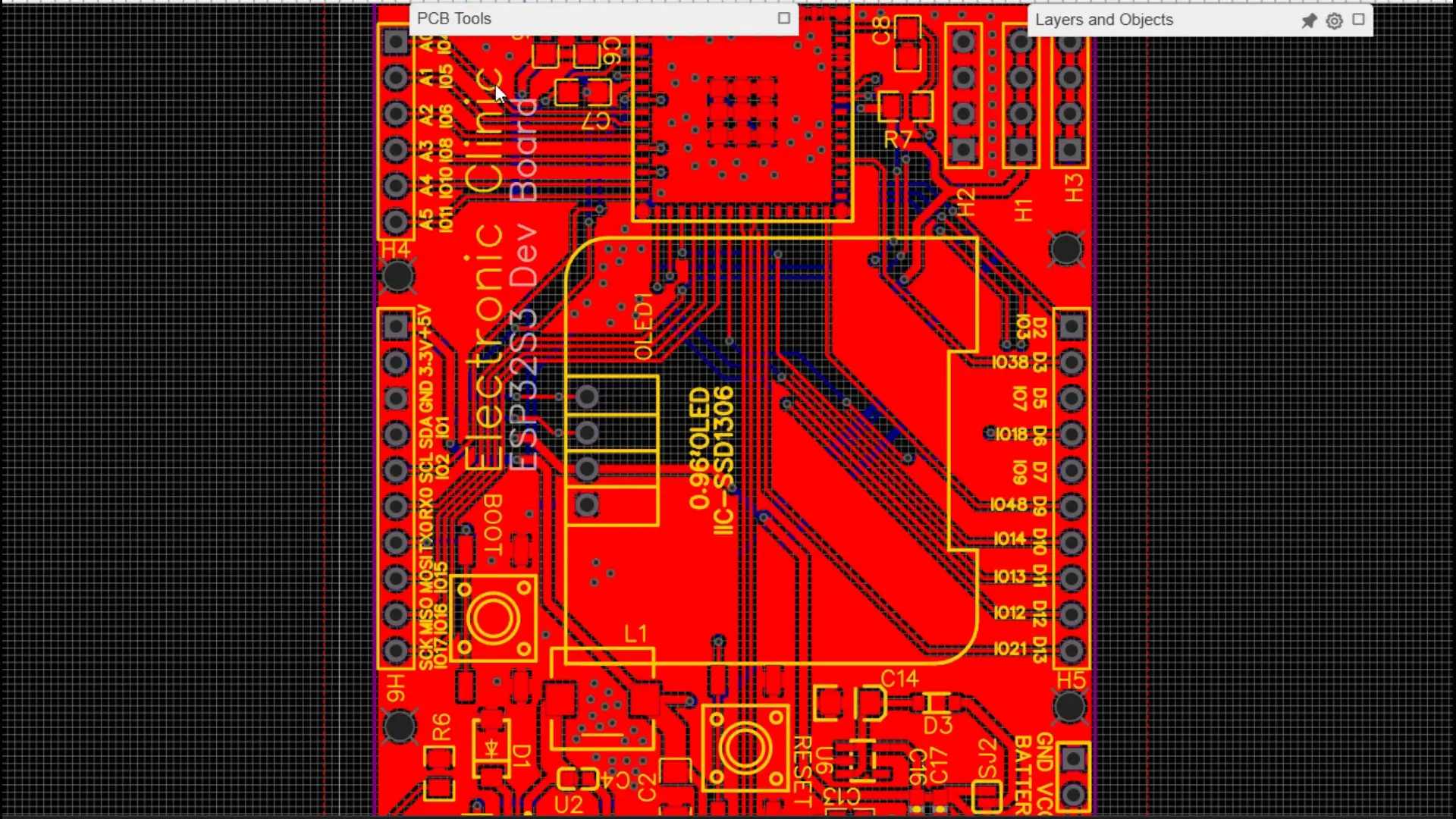
Here is my PCB layout; I have already made several videos on PCB designing. Visit my YouTube Channel “Electronic Clinic”.
I carefully verified the 2D layout, then checked everything in 3D view.
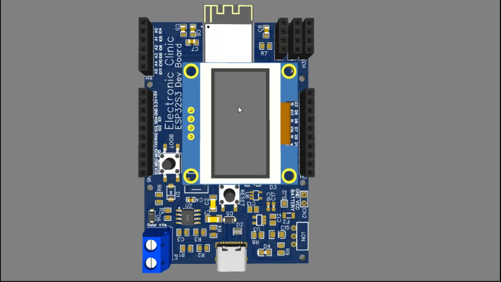
Once everything looked good, I generated the Gerber files.
I used the NextPCB free online Gerber Viewer and DFM Tool (HQDFM); simply drag and drop your files, and it instantly analyzes them.
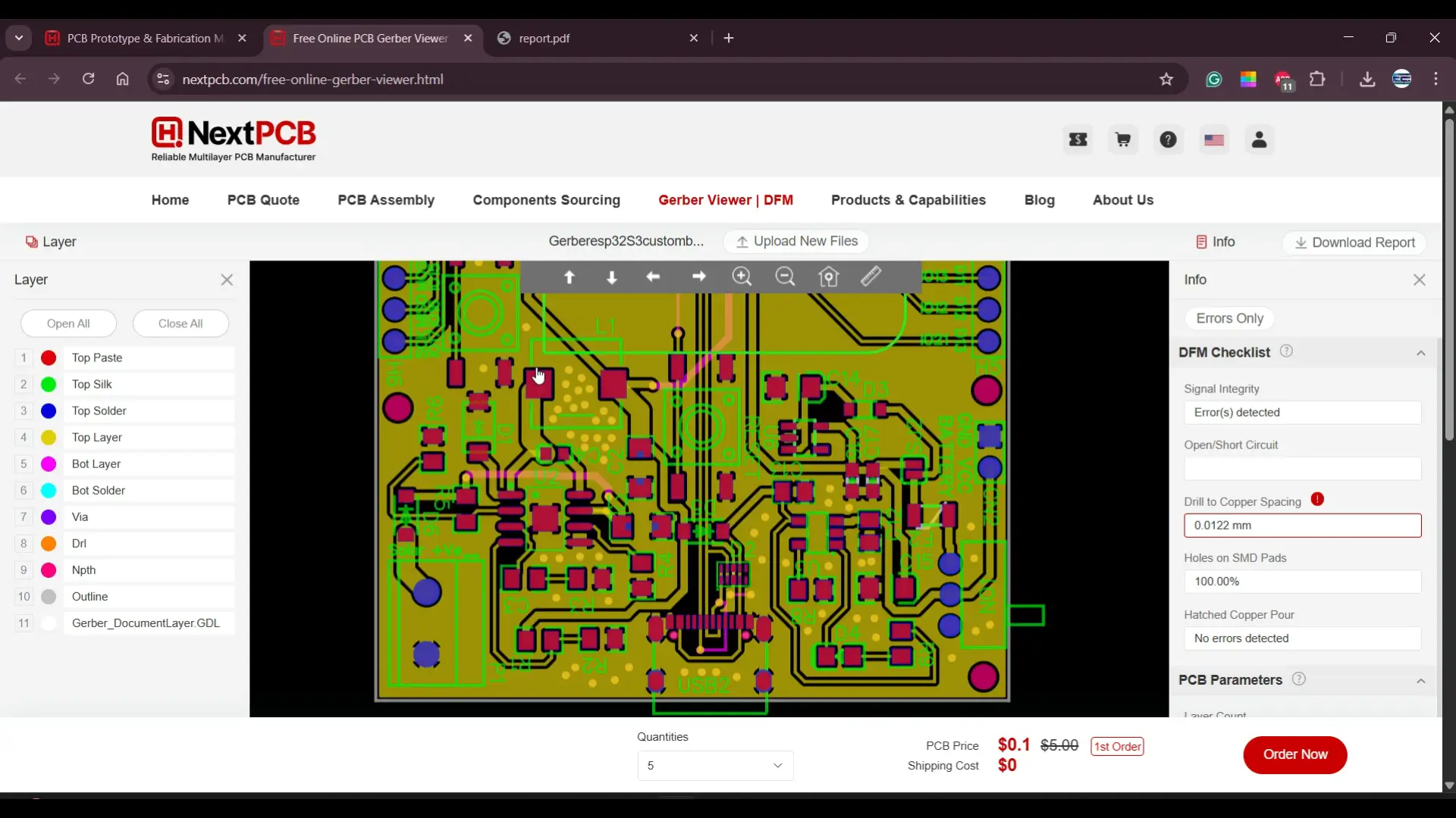
I reviewed both top and bottom layers and used the DFM checklist to identify and fix potential issues.
Since NextPCB offers affordable PCB manufacturing, this time I also chose their assembly service; arranging components myself and doing all the soldering would have taken a lot of time, especially since I need five boards.
Ordering & BOM Customization
I went to the PCB Assembly Quote section, uploaded the Gerber file, and it auto-detected the board size.

I selected 5 boards and chose my preferred solder mask color, leaving the other settings to default.
Finally, I uploaded the Pick-and-Place file and BOM (Bill of Materials). The system quickly showed that most components were in stock.
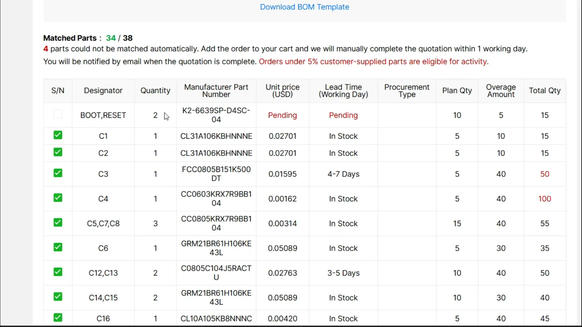
However, to reduce the assembly cost, I marked a few components in the BOM that I already have; I will manually solder those myself.

After a few days, I finally received the PCBs; and just look at the quality! Most of the hard work is already done.
The PCB quality is absolutely top-notch, just as expected. There are a few components missing, which I will be soldering myself.
Since we need to test this board thoroughly and integrate it with some sensors as well, I will first get one board fully assembled and ready for testing.
Once it’s prepared, I will walk you through everything; from the performance to the results. So stay tuned, because things are about to get really exciting!

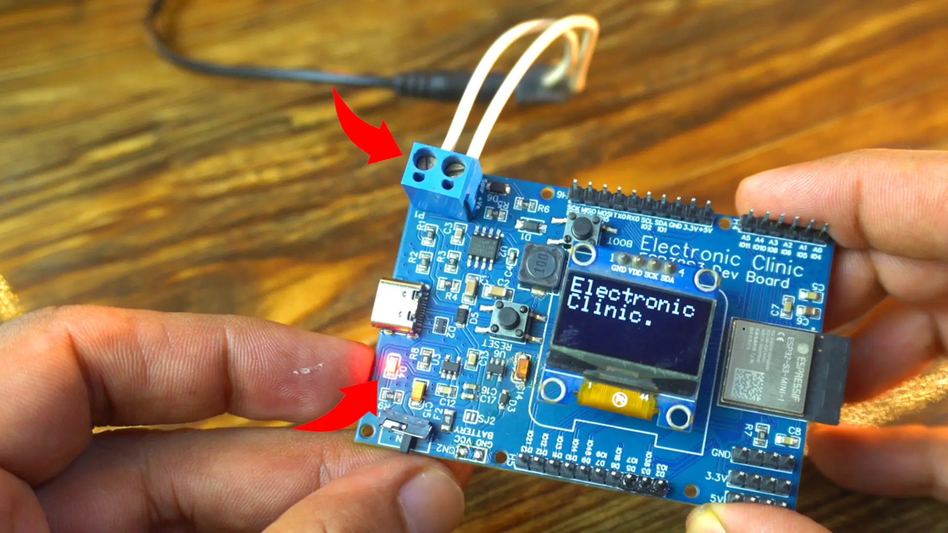
As you can see, I have already soldered all the components, and I have also connected this small 3.7V 400mAh LiPo battery.
So let’s first start with the SSD1306 OLED display module. This way, we will not only test the board but also display some text on the OLED screen.
SSD1306 Oled Display with ESP32S3 Code:
This code simply initializes the SSD1306 OLED display over I²C and then prints the text “Electronic Clinic.” on the screen in a larger font. At the same time, it sends the website link to the Serial Monitor.
|
1 2 3 4 5 6 7 8 9 10 11 12 13 14 15 16 17 18 19 20 21 22 23 24 25 26 27 28 29 30 31 32 33 34 35 36 37 38 39 40 41 42 43 44 45 46 47 |
/* Download Libraries: https://www.electroniclinic.com/arduino-libraries-download-and-projects-they-are-used-in-project-codes/ */ #include <Wire.h> #include <Adafruit_GFX.h> #include <Adafruit_SSD1306.h> // for the OLED display #define SCREEN_WIDTH 128 // OLED display width, in pixels #define SCREEN_HEIGHT 64 // OLED display height, in pixels #define I2C_SDA 1 // GPIO1 #define I2C_SCL 2 // GPIO2 // Declaration for an SSD1306 display connected to I2C (SDA, SCL pins) #define OLED_RESET -1 // Reset pin # (or -1 if sharing Arduino reset pin) Adafruit_SSD1306 display(SCREEN_WIDTH, SCREEN_HEIGHT, &Wire, OLED_RESET); void setup() { Serial.begin(115200); Wire.begin(I2C_SDA, I2C_SCL); display.begin(SSD1306_SWITCHCAPVCC, 0x3C); display.clearDisplay(); display.setTextColor(WHITE); } void loop() { // Display initial text display.setTextSize(2); // Normal 1:1 pixel scale display.setTextColor(SSD1306_WHITE); // Draw white text display.setCursor(0, 0); // Start at top-left corner display.println(F("Electronic\nClinic.")); display.display(); Serial.println("https://www.electroniclinic.com/"); } |
Uploading the Code into ESP32S3:
To upload the code, simply go to the Tools menu > Board > ESP32, and select ESP32S3 Dev Module.

Next, go back to the Tools menu and select the correct communication port.

Since we are also sending the website URL to the Serial Monitor, we will need to enable “USB CDC on Boot”. If you don’t enable this, nothing will be printed to the Serial Monitor. It’s a good idea to keep this enabled during debugging, and once your project is complete, you can disable it again.

I am going to keep it enabled for now, since I want to show you that my ESP32S3-based development board can also print to the Serial Monitor.
Finally, we can go ahead and upload the program.
Practical Demonstration:
As the ESP32S3 boots up, the Serial Monitor instantly comes alive; printing the URL exactly as expected.

This confirms that the USB CDC on Boot setting is working perfectly.
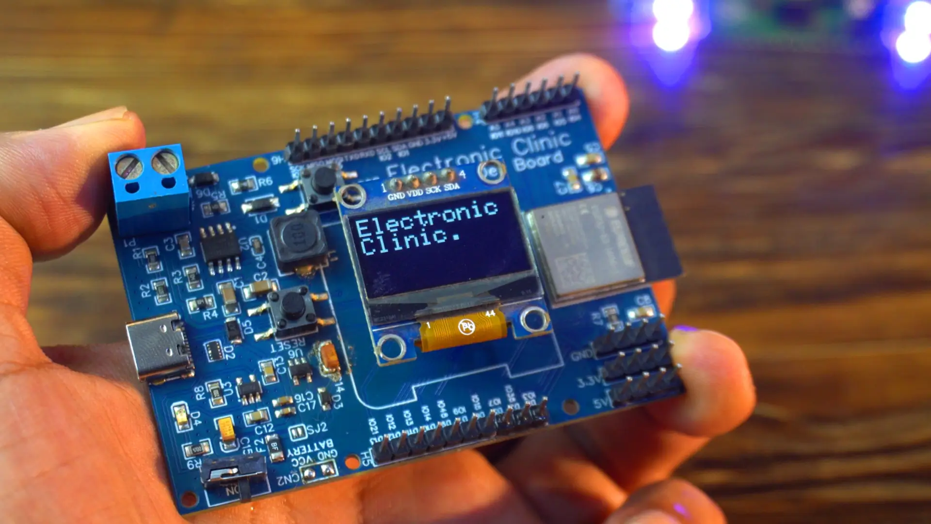
At the same time, the SSD1306 OLED display lights up beautifully, proudly showing the text “Electronic Clinic” in crisp white letters.

It’s always satisfying to watch the hardware and software working together in perfect harmony; proof that my custom ESP32S3 development board is performing flawlessly.
Using the switch I can turn it ON and OFF effortlessly.
ESP32S3 Custom Board Battery Power Test
Now another important test; the battery. I have connected a 3.7V 400mAh LiPo battery to the board, and it works perfectly.
If you need more backup time, you can even connect up to a 1000mAh battery. This makes the board perfect for
- wearable projects
- portable security systems, and
- remote installations; like
farms
forest trails, or
weather stations;
Where you need reliable operation without a wall socket.
On this board, I have also added a blue terminal block for connecting either a 12V adaptor or a solar panel.
This means that during the day, I can run the entire setup on clean, renewable solar energy, and when the sun goes down, the LiPo battery takes over seamlessly.
It’s the perfect balance of sustainability and uninterrupted performance; exactly what you need for modern, off-grid electronics.
I am really satisfied with this development board and that’s why I made another one.

Now, I can start working on wireless projects too. I can use one as the transmitter and the other one as the receiver.
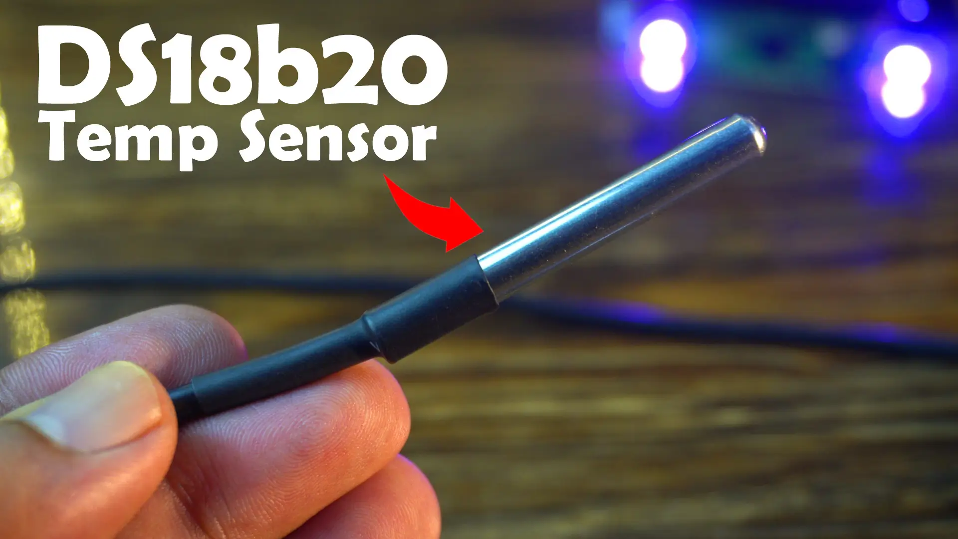
Anyway, now let’s go ahead and check the DS18b20 Waterproof one-wire digital temperature sensor with the ESP32S3 Custom Development board.
DS18b20 Interfacing with ESP32S3 Custom Board:
Connect the red wire of the DS18B20 temperature sensor to 3.3V and the black wire to GND. Then connect the data wire to GPIO5. You can follow this circuit diagram.

DS18b20 ESP32S3 Program:
This code reads temperature data from the DS18B20 sensor and prints it on the SSD1306 OLED display in real time. It’s perfect for projects like water temperature monitoring, weather stations, or any temperature-based automation.
You can download the complete code from my website electroniclinic.com. Let’s go ahead and upload this program.
|
1 2 3 4 5 6 7 8 9 10 11 12 13 14 15 16 17 18 19 20 21 22 23 24 25 26 27 28 29 30 31 32 33 34 35 36 37 38 39 40 41 42 43 44 45 46 47 48 49 50 51 52 53 54 55 56 57 58 59 60 61 62 63 64 65 66 67 68 69 |
#include <Wire.h> #include <Adafruit_GFX.h> #include <Adafruit_SSD1306.h> #include <SimpleTimer.h> #include <OneWire.h> #include <DallasTemperature.h> namespace pin { const byte one_wire_bus = 5; // Dallas Temperature Sensor } namespace sensor { float waterTemp = 0; } #define REPORTING_PERIOD_MS 2000 SimpleTimer timer; uint32_t tsLastReport = 0; // for the OLED display #define SCREEN_WIDTH 128 // OLED display width, in pixels #define SCREEN_HEIGHT 64 // OLED display height, in pixels #define I2C_SDA 1 // GPIO1 #define I2C_SCL 2 // GPIO2 // Declaration for an SSD1306 display connected to I2C (SDA, SCL pins) #define OLED_RESET -1 // Reset pin # (or -1 if sharing Arduino reset pin) Adafruit_SSD1306 display(SCREEN_WIDTH, SCREEN_HEIGHT, &Wire, OLED_RESET); OneWire oneWire(pin::one_wire_bus); DallasTemperature dallasTemperature(&oneWire); void setup() { Serial.begin(115200); dallasTemperature.begin(); Wire.begin(I2C_SDA, I2C_SCL); display.begin(SSD1306_SWITCHCAPVCC, 0x3C); display.clearDisplay(); display.setTextColor(WHITE); } void loop() { dallasTemperature.requestTemperatures(); sensor::waterTemp = dallasTemperature.getTempCByIndex(0); Serial.print(F("Temperature:")); Serial.println(sensor::waterTemp,2); display.clearDisplay(); display.clearDisplay(); display.setTextSize(2); display.setCursor(0, 10); display.print(sensor::waterTemp); display.print((char)247); display.print("C"); display.display(); } |
Practical Demonstration:
I can clearly see the temperature in Celsius on the OLED display.

The moment I touch the DS18B20 sensor, the temperature reading on the display starts to rise… proof that everything is working perfectly in real time.

Next, let’s use the A02YYUW Waterproof Ultrasonic Sensor with the ESP32S3 Development board. And let me tell you, this is the UART version.
A02YYUW Ultrasonic Sensor Interfacing with ESP32S3:

Connect the Red and Black wires to 3.3V and GND pins. Connect the TX and RX pins to the GPIOS 43 and 44.
Programming:
This program is designed to read distance data from the ultrasonic sensor and display it in real time on the OLED display. I have already uploaded this program and let’s watch this in action.
|
1 2 3 4 5 6 7 8 9 10 11 12 13 14 15 16 17 18 19 20 21 22 23 24 25 26 27 28 29 30 31 32 33 34 35 36 37 38 39 40 41 42 43 44 45 46 47 48 49 50 51 52 53 54 55 56 57 58 59 60 61 62 63 64 65 66 67 68 69 70 71 72 73 74 75 76 77 78 79 80 81 82 83 84 85 86 87 88 89 90 91 92 93 94 95 96 97 98 99 |
#include <Wire.h> #include <Adafruit_GFX.h> #include <Adafruit_SSD1306.h> #include <SimpleTimer.h> #include <HardwareSerial.h> HardwareSerial Ultrasonic_Sensor(0); // TX2 (pin 43), RX2 (pin 44) // Define connections to sensor int pinRX = 44; // Choose a suitable pin for RX white wire int pinTX = 43; // Choose a suitable pin for TX yellow wire // Array to store incoming serial data unsigned char data_buffer[4] = {0}; int distance; // Variable to hold checksum unsigned char CS; unsigned long distanceChangeTime; #define REPORTING_PERIOD_MS 2000 SimpleTimer timer; uint32_t tsLastReport = 0; // for the OLED display #define SCREEN_WIDTH 128 // OLED display width, in pixels #define SCREEN_HEIGHT 64 // OLED display height, in pixels #define I2C_SDA 1 // GPIO1 #define I2C_SCL 2 // GPIO2 // Declaration for an SSD1306 display connected to I2C (SDA, SCL pins) #define OLED_RESET -1 // Reset pin # (or -1 if sharing Arduino reset pin) Adafruit_SSD1306 display(SCREEN_WIDTH, SCREEN_HEIGHT, &Wire, OLED_RESET); void setup() { Serial.begin(115200); // Initialize the serial monitor Ultrasonic_Sensor.begin(9600, SERIAL_8N1, pinRX, pinTX); // Initialize the hardware serial Wire.begin(I2C_SDA, I2C_SCL); display.begin(SSD1306_SWITCHCAPVCC, 0x3C); display.clearDisplay(); display.setTextColor(WHITE); } void loop() { // Run if data available if (Ultrasonic_Sensor.available() > 0) { delay(4); // Check for packet header character 0xff if (Ultrasonic_Sensor.read() == 0xff) { // Insert header into array data_buffer[0] = 0xff; // Read remaining 3 characters of data and insert into array for (int i = 1; i < 4; i++) { data_buffer[i] = Ultrasonic_Sensor.read(); } //Compute checksum CS = data_buffer[0] + data_buffer[1] + data_buffer[2]; // If checksum is valid compose distance from data if (data_buffer[3] == CS) { distance = (data_buffer[1] << 8) + data_buffer[2]; // Print to serial monitor distance= distance / 10; // cm } } } Serial.print("distance: "); Serial.print(distance); Serial.println(" cm"); display.clearDisplay(); display.setTextSize(2); display.setCursor(0, 10); display.print("Distance"); display.setTextSize(3); display.setCursor(0, 35); display.print(distance); display.print("cm"); display.display(); } |
Practical Demonstration:
Right now, I have got the ultrasonic sensor connected and running. The OLED display is showing the distance in centimeters.

As I move my hand up and down in front of the sensor, I can see the numbers change instantly on the display. It’s updating in real time, and it’s pretty satisfying to watch how accurately it tracks even small movements.
Testing its onboard 5V 3A Power supply:
With this development board, you don’t need any external power supply; because I have already added a 5V 3A onboard power supply. All you need to do is connect either a solar panel or a 12V DC adaptor, and you are good to go.
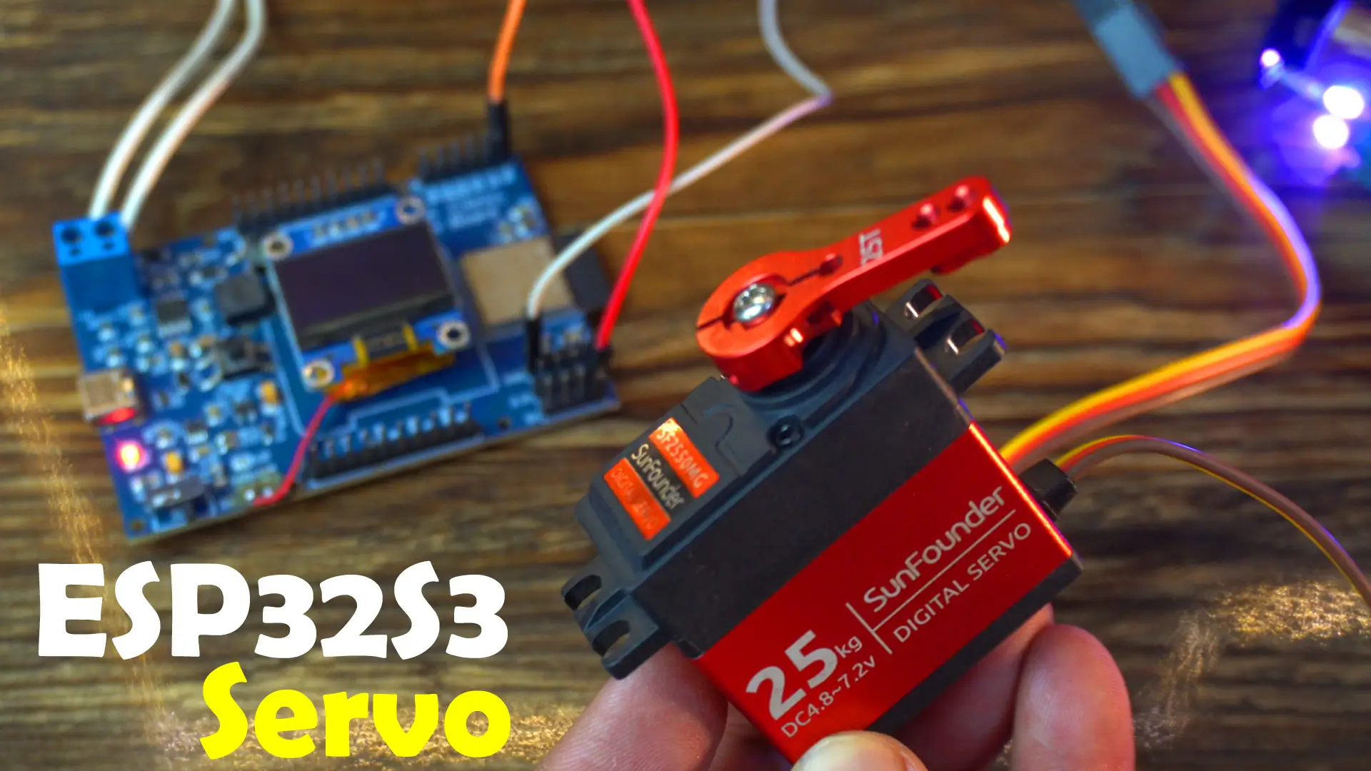
To test the onboard 5V supply, I am going to control this high-torque 25kg servo motor, which requires between 4.8 to 7.2 volts.
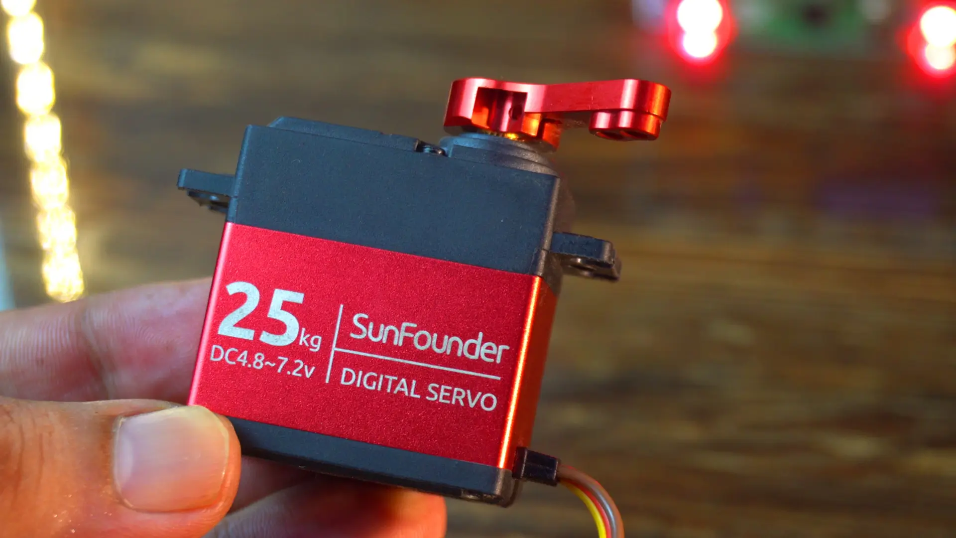
Let’s hook it up to my ESP32-S3 based development board.
Interfacing:
I connected the red wire of the servo to the 5V pin, the brown wire to GND, and the yellow signal wire to GPIO4 of the ESP32S3.
Servo ESP32S3 Program:
This code is designed to control a servo motor connected to GPIO4 of the ESP32-S3, smoothly moving it back and forth between 0° and 90°.
Anyways, I have already uploaded this program and now let’s watch the Servo and my ESP32S3 Development board in action.
|
1 2 3 4 5 6 7 8 9 10 11 12 13 14 15 16 17 18 19 20 21 22 23 24 25 26 |
#include <ESP32Servo.h> Servo myServo; int pos = 0; // Variable to store the servo position void setup() { myServo.attach(4); // Attach servo to GPIO4 } void loop() { // Sweep from 0° to 90° for (pos = 0; pos <= 90; pos++) { myServo.write(pos); delay(15); } delay(100); // Pause // Sweep back from 90° to 0° for (pos = 90; pos >= 0; pos--) { myServo.write(pos); delay(15); } delay(100); // Pause } |
Practical Demonstration:
The servo motor is now sweeping back and forth between 0° and 90°, simulating a controlled mechanical movement.
ESP32S3 Custom Board Indoor Tracking Testing:
![]()
I have also used this development board with MakerFabs’ DW3000 chipset to create a tag for indoor position tracking.
![]()
It successfully communicated with four anchors, and in this way, I was able to flawlessly track the position in real time. The performance was smooth, accurate, and reliable; exactly what’s needed for advanced location-based projects.
Some other Tests:
And that’s not all, I also tested it with the SIM7600G 4G LTE module, and even with LoRa transceiver modules.
If you want the original schematic and PCB files, 9 example projects, Gerber files, BOM file, datasheets, and pick-and-place files, you can download them from my Patreon page.
So, that’s all for now.
Frequently Asked Questions (FAQ)
What makes this ESP32S3 custom board unique?
This custom board is designed for real-world projects, addressing the limitations of common dev kits. Its unique features include a powerful 5V 3A power supply for high-current loads, integrated LiPo battery charging with overcharge protection (MCP73831), flexible power input from a 12V adapter or solar panel, a modern USB-C port with ESD protection, and an onboard SSD1306 OLED display header for easy debugging.
What power sources can this ESP32S3 board use?
The board is highly versatile and can be powered by three main sources: a 3.7V Li-Ion/LiPo battery (up to 1000mAh), a DC power source up to 28V (like a 12V adapter), or directly from a solar panel, making it ideal for portable and off-grid applications.
Where can I download the schematic, PCB layout, and Gerber files?
All the design files, including the complete schematic, PCB layout, Gerber files for manufacturing, Bill of Materials (BOM), pick-and-place files, and all example Arduino codes, are available for download from the author’s official Patreon page.
What specific ESP32-S3 module is used in this project?
This project uses the ESP32-S3-MINI-1 module. It was chosen for its compact size, powerful dual-core 240MHz processor, built-in AI acceleration, and rich peripheral support, making it perfect for a high-performance custom PCB design.
What sensors and components are tested with this board in the article?
The article demonstrates the board’s capabilities by interfacing with several components, including: an SSD1306 OLED display, a DS18B20 waterproof temperature sensor, an A02YYUW waterproof ultrasonic sensor (UART version), and a high-torque 25kg servo motor, proving its robust power delivery and GPIO functionality.
Watch Video Tutorial:
Discover more from Electronic Clinic
Subscribe to get the latest posts sent to your email.


Very good project