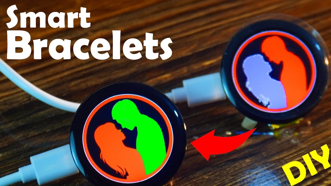
How to make Smart Bracelet for Long distance Couples using ESP32
Last Updated on January 25, 2025 by Engr. Shahzada Fahad
Table of Contents
DIY Smart Bracelets:
How to make Smart Bracelet for Long distance Couples using ESP32- If you want to take your long-distance relationship to the next level, then this article is for you. With these smart bracelets, you can send love signals to each other from anywhere in the world.

You can customize this bracelet and add your own features to surprise your loved one. It might seem a bit complicated, but if you read my last six articles, you will get a clear idea of how to design a smartwatch or a smart bracelet at home and that too for a few bucks.
Before I explain how to make these smart bracelets, I want to share a few things with you guys.
In Part 6, I used the Blynk IoT application to control the vibration motor on the smart bracelet and displayed the counter value on the Gauge in the Blynk application. I also established two-way communication between the smart bracelet and the Blynk application.
But when I tried to use two CrowPanel displays, the Blynk app failed to communicate with both of them. It could only connect to one bracelet at a time. My idea was to use the Blynk app as a bridge between the two bracelets, but after trying for 2 to 3 hours, I couldn’t make it work. If you know how to do this, please let me know in the comments.
So, I switched to Ubidots, and it worked in less than 2 hours.

Now, I am using the Ubidots IoT platform as a bridge between the two smart bracelets. With this setup, I can control both bracelets directly from the Ubidots dashboard.
If you don’t want to use the dashboard, that’s fine too. The two bracelets can exchange love signals directly without needing to open the Ubidots dashboard. I will explain this in more detail later in the article.
In addition to love signals, you can also monitor the counter value.

All the other features are the same as I explained in Part 6. The counter value is still saved in non-volatile memory, and the reset button works exactly the same way. The only difference is that, instead of the Blynk app, I am using the Ubidots IoT platform, and I have already explained why.
I am sure this article will teach you a lot. If you have any ideas, feel free to share them with me in the comments.
So, without any further delay, let’s get started!!!
Amazon Links:
ESP32 WiFi + Bluetooth Module (Recommended)
Other Tools and Components:
Arduino Nano USB C type (Recommended)
*Please Note: These are affiliate links. I may make a commission if you buy the components through these links. I would appreciate your support in this way!
Earlier, there was only one smartwatch or smart bracelet on one side, so I kept all the files in one project folder. But this time, there will be a smart bracelet on both sides.

So, that’s why I made two separate folders: one for the boy and one for the girl. You can download these two folders and the images along with the Arduino code and UI files from my Patreon page.
Anyway, If you are planning to use the same PNG image, you can manage everything with just one project folder. But as you can see, I am using two different PNG images. On the boy’s bracelet, I will animate the girl’s image, and on the girl’s bracelet, I will animate the boy’s image. This way, I can organize all the files properly.
So, let’s start with the boy’s bracelet!
SquareLine Studio Setup:
In the last 6 articles, we have covered a lot of things. In Part 2, I made a counter. In Part 3, I created a digital watch. In Part 4, I made an analog watch. In Part 5, I added dropdown menus to set the time.

And In part 6, I added two more screens (Screen4 and Screen5) for the long distance couples. To keep things simple for you, I decided to continue with the same project.
To import the image click the ADD FILE INTO ASSETS and select the girl.png image.

You can see the image “girl.png” has been added in the Assests.
Next, select the Screen4 and then on the inspector tab go to the background and select the girl.png image.

You can see the image has been changed.
You need to follow the same steps for the girl’s side smart bracelet as well. Anyway, after adding the image, you have to save the project and then export the UI files.
As usual go to the UI files folder, copy all the files and then paste them into the Arduino’s project folder. Then go ahead and open the Arduino file. Follow the same steps for the Girl’s side. For the step-by-step explanation watch the video tutorial on my YouTube channel “Electronic Clinic”.
Boy’s Side Smart Bracelet Code:
|
1 2 3 4 5 6 7 8 9 10 11 12 13 14 15 16 17 18 19 20 21 22 23 24 25 26 27 28 29 30 31 32 33 34 35 36 37 38 39 40 41 42 43 44 45 46 47 48 49 50 51 52 53 54 55 56 57 58 59 60 61 62 63 64 65 66 67 68 69 70 71 72 73 74 75 76 77 78 79 80 81 82 83 84 85 86 87 88 89 90 91 92 93 94 95 96 97 98 99 100 101 102 103 104 105 106 107 108 109 110 111 112 113 114 115 116 117 118 119 120 121 122 123 124 125 126 127 128 129 130 131 132 133 134 135 136 137 138 139 140 141 142 143 144 145 146 147 148 149 150 151 152 153 154 155 156 157 158 159 160 161 162 163 164 165 166 167 168 169 170 171 172 173 174 175 176 177 178 179 180 181 182 183 184 185 186 187 188 189 190 191 192 193 194 195 196 197 198 199 200 201 202 203 204 205 206 207 208 209 210 211 212 213 214 215 216 217 218 219 220 221 222 223 224 225 226 227 228 229 230 231 232 233 234 235 236 237 238 239 240 241 242 243 244 245 246 247 248 249 250 251 252 253 254 255 256 257 258 259 260 261 262 263 264 265 266 267 268 269 270 271 272 273 274 275 276 277 278 279 280 281 282 283 284 285 286 287 288 289 290 291 292 293 294 295 296 297 298 299 300 301 302 303 304 305 306 307 308 309 310 311 312 313 314 315 316 317 318 319 320 321 322 323 324 325 326 327 328 329 330 331 332 333 334 335 336 337 338 339 340 341 342 343 344 345 346 347 348 349 350 351 352 353 354 355 356 357 358 359 360 361 362 363 364 365 366 367 368 369 370 371 372 373 374 375 376 377 378 379 380 381 382 383 384 385 386 387 388 389 390 391 392 393 394 395 396 397 398 399 400 401 402 403 404 405 406 407 408 409 410 411 412 413 414 415 416 417 418 419 420 421 422 423 424 425 426 427 428 429 430 431 432 433 434 435 436 437 438 439 440 441 442 443 444 445 446 447 448 449 450 451 452 453 454 455 456 457 458 459 460 461 462 463 464 465 466 467 468 469 470 471 472 473 474 475 476 477 478 479 480 481 482 483 484 485 486 487 488 489 490 491 492 493 494 495 496 497 498 499 500 501 502 503 504 505 506 507 508 509 510 511 512 513 514 515 516 517 518 519 520 521 522 523 524 525 526 527 528 529 530 531 532 533 534 535 536 537 538 539 540 541 542 543 544 545 546 547 548 549 550 551 552 553 554 555 556 557 558 559 560 561 562 563 564 565 566 567 568 569 570 571 572 573 574 575 576 577 578 579 580 581 582 583 584 585 586 587 588 589 590 591 592 593 594 595 596 597 598 599 600 601 602 603 604 605 606 607 608 609 610 611 612 613 614 615 616 617 618 619 620 621 622 623 624 625 626 627 628 629 630 631 632 633 634 635 636 637 638 639 640 641 642 643 644 645 646 647 648 649 650 651 652 653 654 655 656 657 658 659 660 661 662 663 664 665 666 667 668 669 670 671 672 673 674 675 676 677 678 679 680 681 682 683 684 685 686 687 688 689 690 691 692 693 694 695 696 697 698 699 700 701 702 703 704 705 706 707 708 709 710 711 712 713 714 715 716 717 718 719 720 721 722 723 724 725 726 727 728 |
// boy side #define LGFX_USE_V1 #include "UbidotsEsp32Mqtt.h" #include <WiFi.h> #include "Arduino.h" #include <lvgl.h> #include <LovyanGFX.hpp> #include <Ticker.h> #include "CST816D.h" #include "do_mian.h" #include "ui.h" #include <Preferences.h> #include "I2C_BM8563.h" #include <esp_task_wdt.h> // Include the watchdog timer library /**************************************** * Define Constants ****************************************/ const char *UBIDOTS_TOKEN = "BBUS-0aLke5ZE31QRNqUG04Kq9yJ8FRWEf6"; // Put here your Ubidots TOKEN String ssid = ""; // Put here your Wi-Fi SSID String password = ""; // Put here your Wi-Fi password const char *DEVICE_LABEL = "couples"; // Put here your Device label to which data will be published //from controller to ubidots const char *VARIABLE_LABEL3 = "boy_counter"; //counter value to ubidots const char *VARIABLE_LABEL5 = "boy_notification"; // Notification LED in the ubidots // from ubidots to controller const char *VARIABLE_LABEL4 = "boy_motor"; //This one is to control the vibration motor const char *VARIABLE_LABEL6 = "girl_motor"; //This one is to control the vibration motor const int PUBLISH_FREQUENCY = 5000; // Update rate in milliseconds unsigned long timer; //uint8_t analogPin = 34; // Pin used to read data from GPIO34 ADC_CH6. float value=0; // To store incoming value. //int Relay1 = 13; Ubidots ubidots(UBIDOTS_TOKEN); #define WATCHDOG_TIMEOUT 3 // Time in seconds #define I2C_SDA 4 #define I2C_SCL 5 #define TP_INT 0 #define TP_RST -1 int wificounter = 0; // Timer for reconnect attempts unsigned long lastReconnectAttempt = 0; const unsigned long reconnectInterval = 5000; // Attempt reconnect every 5 seconds Ticker checkwificonnectivity; // Declare Preferences object Preferences preferences; int vibrationmotor = 0; int counter = 0; // For analog watch int h = 0; int m = 0; int s = 0; //encoder #define ENCODER_A_PIN 19 #define ENCODER_B_PIN 18 #define SWITCH_PIN 8 //Custom key pins #define Custom_PIN 1 long position = 0; long position_tmp = 0; bool switchPressed = false; #define PI4IO_I2C_ADDR 0x43 I2C_BM8563 rtc(I2C_BM8563_DEFAULT_ADDRESS, Wire); I2C_BM8563_DateTypeDef dateStruct; I2C_BM8563_TimeTypeDef timeStruct; #define off_pin 35 #define buf_size 120 //Alarm switch sign int fal = 0; //Indicates whether the alarm has gone off int fal1 = 0; uint32_t hourValue = 0; uint32_t minuteValue = 0; class LGFX : public lgfx::LGFX_Device { lgfx::Panel_GC9A01 _panel_instance; lgfx::Bus_SPI _bus_instance; public: LGFX(void) { { auto cfg = _bus_instance.config(); cfg.spi_host = SPI2_HOST; cfg.spi_mode = 0; cfg.freq_write = 80000000; cfg.freq_read = 20000000; cfg.spi_3wire = true; cfg.use_lock = true; cfg.dma_channel = SPI_DMA_CH_AUTO; cfg.pin_sclk = 6; cfg.pin_mosi = 7; cfg.pin_miso = -1; cfg.pin_dc = 2; _bus_instance.config(cfg); _panel_instance.setBus(&_bus_instance); } { auto cfg = _panel_instance.config(); cfg.pin_cs = 10; cfg.pin_rst = -1; cfg.pin_busy = -1; cfg.memory_width = 240; cfg.memory_height = 240; cfg.panel_width = 240; cfg.panel_height = 240; cfg.offset_x = 0; cfg.offset_y = 0; cfg.offset_rotation = 0; cfg.dummy_read_pixel = 8; cfg.dummy_read_bits = 1; cfg.readable = false; cfg.invert = true; cfg.rgb_order = false; cfg.dlen_16bit = false; cfg.bus_shared = false; _panel_instance.config(cfg); } setPanel(&_panel_instance); } }; LGFX tft; CST816D touch(I2C_SDA, I2C_SCL, TP_RST, TP_INT); /*Change to your screen resolution*/ static const uint32_t screenWidth = 240; static const uint32_t screenHeight = 240; static lv_disp_draw_buf_t draw_buf; static lv_color_t buf[2][screenWidth * buf_size]; #if LV_USE_LOG != 0 /* Serial debugging */ void my_print(lv_log_level_t level, const char *file, uint32_t line, const char *fn_name, const char *dsc) { Serial.printf("%s(%s)@%d->%s\r\n", file, fn_name, line, dsc); Serial.flush(); } #endif /* Display flushing */ void my_disp_flush(lv_disp_drv_t *disp, const lv_area_t *area, lv_color_t *color_p) { if (tft.getStartCount() == 0) { tft.endWrite(); } tft.pushImageDMA(area->x1, area->y1, area->x2 - area->x1 + 1, area->y2 - area->y1 + 1, (lgfx::swap565_t *)&color_p->full); lv_disp_flush_ready(disp); /* tell lvgl that flushing is done */ } /*Read the touchpad*/ void my_touchpad_read(lv_indev_drv_t *indev_driver, lv_indev_data_t *data) { bool touched; uint8_t gesture; uint16_t touchX, touchY; touched = touch.getTouch(&touchX, &touchY, &gesture); if (!touched) { data->state = LV_INDEV_STATE_REL; } else { data->state = LV_INDEV_STATE_PR; /*Set the coordinates*/ data->point.x = touchX; data->point.y = touchY; } } Ticker ticker; //Extended IO function void init_IO_extender() { Wire.beginTransmission(PI4IO_I2C_ADDR); Wire.write(0x01); // test register Wire.endTransmission(); Wire.requestFrom(PI4IO_I2C_ADDR, 1); uint8_t rxdata = Wire.read(); Serial.print("Device ID: "); Serial.println(rxdata, HEX); Wire.beginTransmission(PI4IO_I2C_ADDR); Wire.write(0x03); // IO direction register Wire.write((1 << 0) | (1 << 1) | (1 << 2) | (1 << 3) | (1 << 4)); // set pins 0, 1, 2 as outputs Wire.endTransmission(); Wire.beginTransmission(PI4IO_I2C_ADDR); Wire.write(0x07); // Output Hi-Z register Wire.write(~((1 << 0) | (1 << 1) | (1 << 2) | (1 << 3) | (1 << 4))); // set pins 0, 1, 2 low Wire.endTransmission(); } void set_pin_io(uint8_t pin_number, bool value) { Wire.beginTransmission(PI4IO_I2C_ADDR); Wire.write(0x05); // test register Wire.endTransmission(); Wire.requestFrom(PI4IO_I2C_ADDR, 1); uint8_t rxdata = Wire.read(); Serial.print("Before the change: "); Serial.println(rxdata, HEX); Wire.beginTransmission(PI4IO_I2C_ADDR); Wire.write(0x05); // Output register if (!value) Wire.write((~(1 << pin_number)) & rxdata); // set pin low else Wire.write((1 << pin_number) | rxdata); // set pin high Wire.endTransmission(); Wire.beginTransmission(PI4IO_I2C_ADDR); Wire.write(0x05); // test register Wire.endTransmission(); Wire.requestFrom(PI4IO_I2C_ADDR, 1); rxdata = Wire.read(); Serial.print("after the change: "); Serial.println(rxdata, HEX); } //RTC function void RTC_init() { rtc.begin(); // Set custom time // I2C_BM8563_TimeTypeDef timeStruct; // timeStruct.hours = 11; // Hour (0 - 23) // timeStruct.minutes = 59; // Minute (0 - 59) // timeStruct.seconds = 0; // Second (0 - 59) // rtc.setTime(&timeStruct); // I2C_BM8563_DateTypeDef dateStruct; // dateStruct.weekDay = 3; // Weekday (0 - 6, where 0 is Sunday) // dateStruct.month = 1; // Month (1 - 12) // dateStruct.date = 24; // Day of the month (1 - 31) // dateStruct.year = 2024; // Year // rtc.setDate(&dateStruct); } //Encoder function void updateEncoder() { static int previousState = 0; static int flag_A = 0; static int flag_C = 0; int currentState = (digitalRead(ENCODER_A_PIN) << 1) | digitalRead(ENCODER_B_PIN); if ((currentState == 0b00 && previousState == 0b01) || (currentState == 0b01 && previousState == 0b11) || (currentState == 0b11 && previousState == 0b10) || (currentState == 0b10 && previousState == 0b00)) { // foreward // if (switchPressed) { flag_A++; if (flag_A == 50) { flag_A = 0; flag_C = 0; // position++; // position_tmp=position; position_tmp = 1; } // flag_C=0; // } } else if ((currentState == 0b01 && previousState == 0b00) || (currentState == 0b11 && previousState == 0b01) || (currentState == 0b10 && previousState == 0b11) || (currentState == 0b00 && previousState == 0b10)) { // reversal // if (switchPressed) { flag_C++; if (flag_C == 50) { // position--; flag_C = 0; flag_A = 0; // position_tmp=position; position_tmp = 0; } // flag_A=0; // } } previousState = currentState; } void switchPressedInterrupt() { switchPressed = !switchPressed; } void setup() { Serial.begin(115200); /* prepare for possible serial debug */ // Initialize Preferences preferences.begin("wifi-creds", false); /*first we read the ssid and password from the eeprom */ String myssid = preferences.getString("ssid", "No SSID"); String mypassword = preferences.getString("password", "No SSID"); counter = preferences.getInt("counter", 0); // Default to 0 if no value exists //if new ssid and password are saved, then we store default ssid and password in the eeprom // so when first connecting it to the wifi router; set its ssid to Engr Fahad and password to electroniclinic if ( myssid == "" && mypassword == "") { preferences.putString("ssid", "Engr Fahad"); preferences.putString("password", "electroniclinic"); } else // else if ssid and password are already stored in the eeprom then simply retieve them and save them in ssid and password { ssid = preferences.getString("ssid", "No SSID"); password = preferences.getString("password", "No password"); } preferences.end(); // close the namespace // Initialize WiFi, simple code without the eeprom // if by mistake wrong ssid or password is entered then the ssid and password will set to its default values // then again you will have to change your wifi hotspot or wifi router ssid and password to the default values to set the new ssid and password from the smart watch //otherwise the smartwatch screen will show nothing, it will keep looking for the wifi // that's why there is a wificounter, if it doesn't connect to the newly set rounter then its ssid and password will change to Engr Fahad and electroniclinic ubidots.connectToWifi(ssid.c_str(), password.c_str()); while (WiFi.status() != WL_CONNECTED) { delay(500); Serial.print("."); wificounter++; if(wificounter >= 10) { preferences.begin("wifi-creds", false); preferences.putString("ssid", "Engr Fahad"); preferences.putString("password", "electroniclinic"); ssid = preferences.getString("ssid", "No SSID"); password = preferences.getString("password", "No password"); wificounter = 0; preferences.end(); // close the namespace } } Serial.println("\nWiFi connected!"); Wire.begin(4, 5); init_IO_extender(); delay(100); set_pin_io(3, true); set_pin_io(4, true); pinMode(ENCODER_A_PIN, INPUT_PULLUP); pinMode(ENCODER_B_PIN, INPUT_PULLUP); pinMode(SWITCH_PIN, INPUT_PULLUP); pinMode(Custom_PIN, INPUT); attachInterrupt(digitalPinToInterrupt(ENCODER_A_PIN), updateEncoder, CHANGE); attachInterrupt(digitalPinToInterrupt(ENCODER_B_PIN), updateEncoder, CHANGE); attachInterrupt(digitalPinToInterrupt(SWITCH_PIN), switchPressedInterrupt, FALLING); // ticker.attach(1, tcr1s); tft.init(); tft.initDMA(); tft.startWrite(); tft.setColor(0, 0, 0); tft.fillScreen(TFT_BLACK); delay(200); if (is_touch == 1) { touch.begin(); } lv_init(); #if LV_USE_LOG != 0 //lv_log_register_print_cb(my_print); /* register print function for debugging */ #endif lv_disp_draw_buf_init(&draw_buf, buf[0], buf[1], screenWidth * buf_size); /*Initialize the display*/ static lv_disp_drv_t disp_drv; lv_disp_drv_init(&disp_drv); /*Change the following line to your display resolution*/ disp_drv.hor_res = screenWidth; disp_drv.ver_res = screenHeight; disp_drv.flush_cb = my_disp_flush; disp_drv.draw_buf = &draw_buf; lv_disp_drv_register(&disp_drv); /*Initialize the (dummy) input device driver*/ if (is_touch == 1) { static lv_indev_drv_t indev_drv; lv_indev_drv_init(&indev_drv); indev_drv.type = LV_INDEV_TYPE_POINTER; indev_drv.read_cb = my_touchpad_read; lv_indev_drv_register(&indev_drv); } #if 0 /* Create simple label */ lv_obj_t *label = lv_label_create( lv_scr_act() ); lv_label_set_text( label, "Hello Arduino! (V8.0.X)" ); lv_obj_align( label, LV_ALIGN_CENTER, 0, 0 ); #else /* Try an example from the lv_examples Arduino library make sure to include it as written above. lv_example_btn_1(); */ // uncomment one of these demos // lv_demo_widgets(); // OK // lv_demo_benchmark(); // OK // lv_demo_keypad_encoder(); // works, but I haven't an encoder // lv_demo_music(); // NOK // lv_demo_printer(); // lv_demo_stress(); // seems to be OK ui_mian(); // watch #endif Serial.println("Setup done"); // delay(200); set_pin_io(2, true); pinMode(3, OUTPUT); digitalWrite(3, LOW); // pinMode(0, INPUT); // Get RTC RTC_init(); rtc.getDate(&dateStruct); rtc.getTime(&timeStruct); // Configuration structure for the watchdog timer esp_task_wdt_config_t wdtConfig = { .timeout_ms = WATCHDOG_TIMEOUT * 1000, // Timeout in milliseconds .idle_core_mask = 0, // Monitor core 0 .trigger_panic = true // Trigger panic on timeout }; // Initialize the Task Watchdog Timer esp_task_wdt_init(&wdtConfig); esp_task_wdt_add(NULL); // Add the current task to the watchdog // ubidots.setDebug(true); // uncomment this to make debug messages available ubidots.connectToWifi(ssid.c_str(), password.c_str()); ubidots.setCallback(callback); ubidots.setup(); ubidots.reconnect(); timer = millis(); ubidots.subscribeLastValue(DEVICE_LABEL, VARIABLE_LABEL4); // button in ubidots to control the vibration motor boy side ubidots.subscribeLastValue(DEVICE_LABEL, VARIABLE_LABEL6); // button in ubidots to control the vibration motor girl side } //void Watch_Function(void *param) void loop() { esp_task_wdt_reset(); // Reset the watchdog timer lv_timer_handler(); /* let the GUI do its work */ delay(5); // Small delay for smoother operation // put your main code here, to run repeatedly: if (!ubidots.connected()) { ubidots.reconnect(); ubidots.subscribeLastValue(DEVICE_LABEL, VARIABLE_LABEL4); // button in ubidots to control the vibration motor boy side ubidots.subscribeLastValue(DEVICE_LABEL, VARIABLE_LABEL6); // button in ubidots to control the vibration motor girl side } if ((millis() - timer) > PUBLISH_FREQUENCY) // triggers the routine every 5 seconds { //float value = analogRead(analogPin); ubidots.add(VARIABLE_LABEL3, counter); // Insert your variable Labels and the value to be sent ubidots.publish(DEVICE_LABEL); timer = millis(); //Serial.println(VARIABLE_LABEL3); } ubidots.loop(); lv_label_set_text(ui_lblCounter, String(counter).c_str()); rtc.getTime(&timeStruct); // Get the current time from the RTC lv_label_set_text(ui_lblHours, String(timeStruct.hours).c_str()); lv_label_set_text(ui_lblminutes, String(timeStruct.minutes).c_str()); lv_label_set_text(ui_lblseconds, String(timeStruct.seconds).c_str()); /****************** For Analog Watch ****************/ h = timeStruct.hours; m = timeStruct.minutes; // s = timeStruct.seconds * 60 % 3600; //Initializing the alarm page from the RTC // lv_img_set_angle(ui_shand, s); // lv_img_set_angle(ui_shand2, s); lv_img_set_angle(ui_imageMinuteHand, m * 60); lv_img_set_angle(ui_imageHourHand, h * 300 + m / 12 * 60); lv_img_set_angle(ui_imageMinuteHand, m * 60); lv_img_set_angle(ui_imageHourHand, h * 300 + m / 12 * 60); handleToggling(); } void ResetCounter(lv_event_t * e) { counter = 0; ubidots.add(VARIABLE_LABEL3, counter); // Insert your variable Labels and the value to be sent ubidots.publish(DEVICE_LABEL); preferences.begin("wifi-creds", false); preferences.putInt("counter", counter); // Save counter immediately preferences.end(); } void incrementCounter(lv_event_t * e) { counter++; ubidots.add(VARIABLE_LABEL3, counter); // Insert your variable Labels and the value to be sent ubidots.publish(DEVICE_LABEL); preferences.begin("wifi-creds", false); preferences.putInt("counter", counter); // Save counter immediately preferences.end(); } void setthehours(lv_event_t * e) { // Buffer to store the selected option text char myHour[25]; // Adjust size based on the longest dropdown option ui_Dropdown3 = lv_event_get_target(e); lv_dropdown_get_selected_str(ui_Dropdown3, myHour, sizeof(myHour)); timeStruct.hours = atoi(myHour); rtc.setTime(&timeStruct); } void Settheminutes(lv_event_t * e) { char myMinutes[61]; // Adjust size based on the longest dropdown option ui_Dropdown1 = lv_event_get_target(e); lv_dropdown_get_selected_str(ui_Dropdown1, myMinutes, sizeof(myMinutes)); timeStruct.minutes = atoi(myMinutes); rtc.setTime(&timeStruct); } void applyssidpassword(lv_event_t * e) { // Get text from the text holders ssid = lv_textarea_get_text(ui_txtssid); password = lv_textarea_get_text(ui_txtpassword); preferences.begin("wifi-creds", false); // Save to Preferences preferences.putString("ssid", ssid); preferences.putString("password", password); ssid = preferences.getString("ssid", "No SSID"); password = preferences.getString("password", "No password"); preferences.end(); } unsigned long previousMillis = 0; // Tracks the last recorded time const unsigned long interval = 500; // 500 milliseconds delay int toggleCount = 0; // Counter for toggles const int maxToggles = 10; // Total toggles (5 times for each color) bool toggle = false; // Tracks which color to show bool isToggling = false; // Indicates whether toggling is active void notification(lv_event_t * e) // when you long press on the screen 4 { startToggling(); } void startToggling() { toggleCount = 0; // Reset the toggle count isToggling = true; // Activate toggling } void handleToggling() { if (!isToggling) return; // Exit if toggling is not active unsigned long currentMillis = millis(); if (currentMillis - previousMillis >= interval) { previousMillis = currentMillis; // Update the last recorded time // Toggle the background color if (toggle) { lv_obj_set_style_bg_color(ui_Screen4, lv_color_hex(0xFF0000), LV_PART_MAIN | LV_STATE_DEFAULT); ubidots.add(VARIABLE_LABEL5, 0); ubidots.add(VARIABLE_LABEL6, 0); // controls the vibraation motor on the girl's side ubidots.publish(DEVICE_LABEL); set_pin_io(0, false); // Set pin 0 to high } else { lv_obj_set_style_bg_color(ui_Screen4, lv_color_hex(0x00FF17), LV_PART_MAIN | LV_STATE_DEFAULT); ubidots.add(VARIABLE_LABEL5, 1); ubidots.add(VARIABLE_LABEL6, 1); // controls the vibraation motor on the girl's side ubidots.publish(DEVICE_LABEL); set_pin_io(0, true); // Set pin 0 to high } toggle = !toggle; // Alternate the toggle state toggleCount++; // Increment the toggle count if (toggleCount >= maxToggles) { isToggling = false; // Stop toggling after max toggles } } } /**************************************** * Auxiliar Functions ****************************************/ // cast from an array of chars to float value. float btof(byte * payload, unsigned int length) { char * demo = (char *) malloc(sizeof(char) * 10); for (int i = 0; i < length; i++) { demo[i] = payload[i]; } float value = atof(demo); free(demo); return value; } // Callback to handle subscription void callback(char* topic, byte* payload, unsigned int length) { value = btof(payload, length); Serial.println(value); if (value == 0.00) { lv_scr_load(ui_Screen4); // This switches to ui_Screen4 lv_obj_set_style_bg_color(ui_Screen4, lv_color_hex(0xFF0000), LV_PART_MAIN | LV_STATE_DEFAULT); set_pin_io(0, false); // Set pin 0 to low } if (value == 1.00) { lv_scr_load(ui_Screen4); // This switches to ui_Screen4 lv_obj_set_style_bg_color(ui_Screen4, lv_color_hex(0x00FF17), LV_PART_MAIN | LV_STATE_DEFAULT); set_pin_io(0, true); // Set pin 0 to low } } |
Girl’s Side Smart Bracelet Code:
|
1 2 3 4 5 6 7 8 9 10 11 12 13 14 15 16 17 18 19 20 21 22 23 24 25 26 27 28 29 30 31 32 33 34 35 36 37 38 39 40 41 42 43 44 45 46 47 48 49 50 51 52 53 54 55 56 57 58 59 60 61 62 63 64 65 66 67 68 69 70 71 72 73 74 75 76 77 78 79 80 81 82 83 84 85 86 87 88 89 90 91 92 93 94 95 96 97 98 99 100 101 102 103 104 105 106 107 108 109 110 111 112 113 114 115 116 117 118 119 120 121 122 123 124 125 126 127 128 129 130 131 132 133 134 135 136 137 138 139 140 141 142 143 144 145 146 147 148 149 150 151 152 153 154 155 156 157 158 159 160 161 162 163 164 165 166 167 168 169 170 171 172 173 174 175 176 177 178 179 180 181 182 183 184 185 186 187 188 189 190 191 192 193 194 195 196 197 198 199 200 201 202 203 204 205 206 207 208 209 210 211 212 213 214 215 216 217 218 219 220 221 222 223 224 225 226 227 228 229 230 231 232 233 234 235 236 237 238 239 240 241 242 243 244 245 246 247 248 249 250 251 252 253 254 255 256 257 258 259 260 261 262 263 264 265 266 267 268 269 270 271 272 273 274 275 276 277 278 279 280 281 282 283 284 285 286 287 288 289 290 291 292 293 294 295 296 297 298 299 300 301 302 303 304 305 306 307 308 309 310 311 312 313 314 315 316 317 318 319 320 321 322 323 324 325 326 327 328 329 330 331 332 333 334 335 336 337 338 339 340 341 342 343 344 345 346 347 348 349 350 351 352 353 354 355 356 357 358 359 360 361 362 363 364 365 366 367 368 369 370 371 372 373 374 375 376 377 378 379 380 381 382 383 384 385 386 387 388 389 390 391 392 393 394 395 396 397 398 399 400 401 402 403 404 405 406 407 408 409 410 411 412 413 414 415 416 417 418 419 420 421 422 423 424 425 426 427 428 429 430 431 432 433 434 435 436 437 438 439 440 441 442 443 444 445 446 447 448 449 450 451 452 453 454 455 456 457 458 459 460 461 462 463 464 465 466 467 468 469 470 471 472 473 474 475 476 477 478 479 480 481 482 483 484 485 486 487 488 489 490 491 492 493 494 495 496 497 498 499 500 501 502 503 504 505 506 507 508 509 510 511 512 513 514 515 516 517 518 519 520 521 522 523 524 525 526 527 528 529 530 531 532 533 534 535 536 537 538 539 540 541 542 543 544 545 546 547 548 549 550 551 552 553 554 555 556 557 558 559 560 561 562 563 564 565 566 567 568 569 570 571 572 573 574 575 576 577 578 579 580 581 582 583 584 585 586 587 588 589 590 591 592 593 594 595 596 597 598 599 600 601 602 603 604 605 606 607 608 609 610 611 612 613 614 615 616 617 618 619 620 621 622 623 624 625 626 627 628 629 630 631 632 633 634 635 636 637 638 639 640 641 642 643 644 645 646 647 648 649 650 651 652 653 654 655 656 657 658 659 660 661 662 663 664 665 666 667 668 669 670 671 672 673 674 675 676 677 678 679 680 681 682 683 684 685 686 687 688 689 690 691 692 693 694 695 696 697 698 699 700 701 702 703 704 705 706 707 708 709 710 711 712 713 714 715 716 717 718 719 720 721 722 723 724 725 726 727 728 729 |
// girl side #define LGFX_USE_V1 #include "UbidotsEsp32Mqtt.h" #include <WiFi.h> #include "Arduino.h" #include <lvgl.h> #include <LovyanGFX.hpp> #include <Ticker.h> #include "CST816D.h" #include "do_mian.h" #include "ui.h" #include <Preferences.h> #include "I2C_BM8563.h" #include <esp_task_wdt.h> // Include the watchdog timer library /**************************************** * Define Constants ****************************************/ const char *UBIDOTS_TOKEN = "BBUS-0aLke5ZE31QRNqUG04Kq9yJ8FRWEf6"; // Put here your Ubidots TOKEN String ssid = ""; // Put here your Wi-Fi SSID String password = ""; // Put here your Wi-Fi password const char *DEVICE_LABEL = "couples"; // Put here your Device label to which data will be published //from controller to ubidots const char *VARIABLE_LABEL3 = "girl_counter"; //counter value to ubidots const char *VARIABLE_LABEL5 = "girl_notification"; // Notification LED in the ubidots // from ubidots to controller const char *VARIABLE_LABEL4 = "girl_motor"; //This one is to control the vibration motor const char *VARIABLE_LABEL6 = "boy_motor"; //This one is to control the vibration motor on the boy side const int PUBLISH_FREQUENCY = 5000; // Update rate in milliseconds unsigned long timer; //uint8_t analogPin = 34; // Pin used to read data from GPIO34 ADC_CH6. float value=0; // To store incoming value. //int Relay1 = 13; Ubidots ubidots(UBIDOTS_TOKEN); #define WATCHDOG_TIMEOUT 3 // Time in seconds #define I2C_SDA 4 #define I2C_SCL 5 #define TP_INT 0 #define TP_RST -1 int wificounter = 0; // Timer for reconnect attempts unsigned long lastReconnectAttempt = 0; const unsigned long reconnectInterval = 5000; // Attempt reconnect every 5 seconds Ticker checkwificonnectivity; // Declare Preferences object Preferences preferences; int vibrationmotor = 0; int counter = 0; // For analog watch int h = 0; int m = 0; int s = 0; //encoder #define ENCODER_A_PIN 19 #define ENCODER_B_PIN 18 #define SWITCH_PIN 8 //Custom key pins #define Custom_PIN 1 long position = 0; long position_tmp = 0; bool switchPressed = false; #define PI4IO_I2C_ADDR 0x43 I2C_BM8563 rtc(I2C_BM8563_DEFAULT_ADDRESS, Wire); I2C_BM8563_DateTypeDef dateStruct; I2C_BM8563_TimeTypeDef timeStruct; #define off_pin 35 #define buf_size 120 //Alarm switch sign int fal = 0; //Indicates whether the alarm has gone off int fal1 = 0; uint32_t hourValue = 0; uint32_t minuteValue = 0; class LGFX : public lgfx::LGFX_Device { lgfx::Panel_GC9A01 _panel_instance; lgfx::Bus_SPI _bus_instance; public: LGFX(void) { { auto cfg = _bus_instance.config(); cfg.spi_host = SPI2_HOST; cfg.spi_mode = 0; cfg.freq_write = 80000000; cfg.freq_read = 20000000; cfg.spi_3wire = true; cfg.use_lock = true; cfg.dma_channel = SPI_DMA_CH_AUTO; cfg.pin_sclk = 6; cfg.pin_mosi = 7; cfg.pin_miso = -1; cfg.pin_dc = 2; _bus_instance.config(cfg); _panel_instance.setBus(&_bus_instance); } { auto cfg = _panel_instance.config(); cfg.pin_cs = 10; cfg.pin_rst = -1; cfg.pin_busy = -1; cfg.memory_width = 240; cfg.memory_height = 240; cfg.panel_width = 240; cfg.panel_height = 240; cfg.offset_x = 0; cfg.offset_y = 0; cfg.offset_rotation = 0; cfg.dummy_read_pixel = 8; cfg.dummy_read_bits = 1; cfg.readable = false; cfg.invert = true; cfg.rgb_order = false; cfg.dlen_16bit = false; cfg.bus_shared = false; _panel_instance.config(cfg); } setPanel(&_panel_instance); } }; LGFX tft; CST816D touch(I2C_SDA, I2C_SCL, TP_RST, TP_INT); /*Change to your screen resolution*/ static const uint32_t screenWidth = 240; static const uint32_t screenHeight = 240; static lv_disp_draw_buf_t draw_buf; static lv_color_t buf[2][screenWidth * buf_size]; #if LV_USE_LOG != 0 /* Serial debugging */ void my_print(lv_log_level_t level, const char *file, uint32_t line, const char *fn_name, const char *dsc) { Serial.printf("%s(%s)@%d->%s\r\n", file, fn_name, line, dsc); Serial.flush(); } #endif /* Display flushing */ void my_disp_flush(lv_disp_drv_t *disp, const lv_area_t *area, lv_color_t *color_p) { if (tft.getStartCount() == 0) { tft.endWrite(); } tft.pushImageDMA(area->x1, area->y1, area->x2 - area->x1 + 1, area->y2 - area->y1 + 1, (lgfx::swap565_t *)&color_p->full); lv_disp_flush_ready(disp); /* tell lvgl that flushing is done */ } /*Read the touchpad*/ void my_touchpad_read(lv_indev_drv_t *indev_driver, lv_indev_data_t *data) { bool touched; uint8_t gesture; uint16_t touchX, touchY; touched = touch.getTouch(&touchX, &touchY, &gesture); if (!touched) { data->state = LV_INDEV_STATE_REL; } else { data->state = LV_INDEV_STATE_PR; /*Set the coordinates*/ data->point.x = touchX; data->point.y = touchY; } } Ticker ticker; //Extended IO function void init_IO_extender() { Wire.beginTransmission(PI4IO_I2C_ADDR); Wire.write(0x01); // test register Wire.endTransmission(); Wire.requestFrom(PI4IO_I2C_ADDR, 1); uint8_t rxdata = Wire.read(); Serial.print("Device ID: "); Serial.println(rxdata, HEX); Wire.beginTransmission(PI4IO_I2C_ADDR); Wire.write(0x03); // IO direction register Wire.write((1 << 0) | (1 << 1) | (1 << 2) | (1 << 3) | (1 << 4)); // set pins 0, 1, 2 as outputs Wire.endTransmission(); Wire.beginTransmission(PI4IO_I2C_ADDR); Wire.write(0x07); // Output Hi-Z register Wire.write(~((1 << 0) | (1 << 1) | (1 << 2) | (1 << 3) | (1 << 4))); // set pins 0, 1, 2 low Wire.endTransmission(); } void set_pin_io(uint8_t pin_number, bool value) { Wire.beginTransmission(PI4IO_I2C_ADDR); Wire.write(0x05); // test register Wire.endTransmission(); Wire.requestFrom(PI4IO_I2C_ADDR, 1); uint8_t rxdata = Wire.read(); Serial.print("Before the change: "); Serial.println(rxdata, HEX); Wire.beginTransmission(PI4IO_I2C_ADDR); Wire.write(0x05); // Output register if (!value) Wire.write((~(1 << pin_number)) & rxdata); // set pin low else Wire.write((1 << pin_number) | rxdata); // set pin high Wire.endTransmission(); Wire.beginTransmission(PI4IO_I2C_ADDR); Wire.write(0x05); // test register Wire.endTransmission(); Wire.requestFrom(PI4IO_I2C_ADDR, 1); rxdata = Wire.read(); Serial.print("after the change: "); Serial.println(rxdata, HEX); } //RTC function void RTC_init() { rtc.begin(); // Set custom time // I2C_BM8563_TimeTypeDef timeStruct; // timeStruct.hours = 11; // Hour (0 - 23) // timeStruct.minutes = 59; // Minute (0 - 59) // timeStruct.seconds = 0; // Second (0 - 59) // rtc.setTime(&timeStruct); // I2C_BM8563_DateTypeDef dateStruct; // dateStruct.weekDay = 3; // Weekday (0 - 6, where 0 is Sunday) // dateStruct.month = 1; // Month (1 - 12) // dateStruct.date = 24; // Day of the month (1 - 31) // dateStruct.year = 2024; // Year // rtc.setDate(&dateStruct); } //Encoder function void updateEncoder() { static int previousState = 0; static int flag_A = 0; static int flag_C = 0; int currentState = (digitalRead(ENCODER_A_PIN) << 1) | digitalRead(ENCODER_B_PIN); if ((currentState == 0b00 && previousState == 0b01) || (currentState == 0b01 && previousState == 0b11) || (currentState == 0b11 && previousState == 0b10) || (currentState == 0b10 && previousState == 0b00)) { // foreward // if (switchPressed) { flag_A++; if (flag_A == 50) { flag_A = 0; flag_C = 0; // position++; // position_tmp=position; position_tmp = 1; } // flag_C=0; // } } else if ((currentState == 0b01 && previousState == 0b00) || (currentState == 0b11 && previousState == 0b01) || (currentState == 0b10 && previousState == 0b11) || (currentState == 0b00 && previousState == 0b10)) { // reversal // if (switchPressed) { flag_C++; if (flag_C == 50) { // position--; flag_C = 0; flag_A = 0; // position_tmp=position; position_tmp = 0; } // flag_A=0; // } } previousState = currentState; } void switchPressedInterrupt() { switchPressed = !switchPressed; } void setup() { Serial.begin(115200); /* prepare for possible serial debug */ // Initialize Preferences preferences.begin("wifi-creds", false); /*first we read the ssid and password from the eeprom */ String myssid = preferences.getString("ssid", "No SSID"); String mypassword = preferences.getString("password", "No SSID"); counter = preferences.getInt("counter", 0); // Default to 0 if no value exists //if new ssid and password are saved, then we store default ssid and password in the eeprom // so when first connecting it to the wifi router; set its ssid to Engr Fahad and password to electroniclinic if ( myssid == "" && mypassword == "") { preferences.putString("ssid", "Engr Fahad"); preferences.putString("password", "electroniclinic"); } else // else if ssid and password are already stored in the eeprom then simply retieve them and save them in ssid and password { ssid = preferences.getString("ssid", "No SSID"); password = preferences.getString("password", "No password"); } preferences.end(); // close the namespace // Initialize WiFi, simple code without the eeprom // if by mistake wrong ssid or password is entered then the ssid and password will set to its default values // then again you will have to change your wifi hotspot or wifi router ssid and password to the default values to set the new ssid and password from the smart watch //otherwise the smartwatch screen will show nothing, it will keep looking for the wifi // that's why there is a wificounter, if it doesn't connect to the newly set rounter then its ssid and password will change to Engr Fahad and electroniclinic ubidots.connectToWifi(ssid.c_str(), password.c_str()); while (WiFi.status() != WL_CONNECTED) { delay(500); Serial.print("."); wificounter++; if(wificounter >= 10) { preferences.begin("wifi-creds", false); preferences.putString("ssid", "Engr Fahad"); preferences.putString("password", "electroniclinic"); ssid = preferences.getString("ssid", "No SSID"); password = preferences.getString("password", "No password"); wificounter = 0; preferences.end(); // close the namespace } } Serial.println("\nWiFi connected!"); Wire.begin(4, 5); init_IO_extender(); delay(100); set_pin_io(3, true); set_pin_io(4, true); pinMode(ENCODER_A_PIN, INPUT_PULLUP); pinMode(ENCODER_B_PIN, INPUT_PULLUP); pinMode(SWITCH_PIN, INPUT_PULLUP); pinMode(Custom_PIN, INPUT); attachInterrupt(digitalPinToInterrupt(ENCODER_A_PIN), updateEncoder, CHANGE); attachInterrupt(digitalPinToInterrupt(ENCODER_B_PIN), updateEncoder, CHANGE); attachInterrupt(digitalPinToInterrupt(SWITCH_PIN), switchPressedInterrupt, FALLING); // ticker.attach(1, tcr1s); tft.init(); tft.initDMA(); tft.startWrite(); tft.setColor(0, 0, 0); tft.fillScreen(TFT_BLACK); delay(200); if (is_touch == 1) { touch.begin(); } lv_init(); #if LV_USE_LOG != 0 //lv_log_register_print_cb(my_print); /* register print function for debugging */ #endif lv_disp_draw_buf_init(&draw_buf, buf[0], buf[1], screenWidth * buf_size); /*Initialize the display*/ static lv_disp_drv_t disp_drv; lv_disp_drv_init(&disp_drv); /*Change the following line to your display resolution*/ disp_drv.hor_res = screenWidth; disp_drv.ver_res = screenHeight; disp_drv.flush_cb = my_disp_flush; disp_drv.draw_buf = &draw_buf; lv_disp_drv_register(&disp_drv); /*Initialize the (dummy) input device driver*/ if (is_touch == 1) { static lv_indev_drv_t indev_drv; lv_indev_drv_init(&indev_drv); indev_drv.type = LV_INDEV_TYPE_POINTER; indev_drv.read_cb = my_touchpad_read; lv_indev_drv_register(&indev_drv); } #if 0 /* Create simple label */ lv_obj_t *label = lv_label_create( lv_scr_act() ); lv_label_set_text( label, "Hello Arduino! (V8.0.X)" ); lv_obj_align( label, LV_ALIGN_CENTER, 0, 0 ); #else /* Try an example from the lv_examples Arduino library make sure to include it as written above. lv_example_btn_1(); */ // uncomment one of these demos // lv_demo_widgets(); // OK // lv_demo_benchmark(); // OK // lv_demo_keypad_encoder(); // works, but I haven't an encoder // lv_demo_music(); // NOK // lv_demo_printer(); // lv_demo_stress(); // seems to be OK ui_mian(); // watch #endif Serial.println("Setup done"); // delay(200); set_pin_io(2, true); pinMode(3, OUTPUT); digitalWrite(3, LOW); // pinMode(0, INPUT); // Get RTC RTC_init(); rtc.getDate(&dateStruct); rtc.getTime(&timeStruct); // Configuration structure for the watchdog timer esp_task_wdt_config_t wdtConfig = { .timeout_ms = WATCHDOG_TIMEOUT * 1000, // Timeout in milliseconds .idle_core_mask = 0, // Monitor core 0 .trigger_panic = true // Trigger panic on timeout }; // Initialize the Task Watchdog Timer esp_task_wdt_init(&wdtConfig); esp_task_wdt_add(NULL); // Add the current task to the watchdog // ubidots.setDebug(true); // uncomment this to make debug messages available ubidots.connectToWifi(ssid.c_str(), password.c_str()); ubidots.setCallback(callback); ubidots.setup(); ubidots.reconnect(); timer = millis(); ubidots.subscribeLastValue(DEVICE_LABEL, VARIABLE_LABEL4); // button in ubidots to control the vibration motor ubidots.subscribeLastValue(DEVICE_LABEL, VARIABLE_LABEL6); // button in ubidots to control the vibration motor, boy side } //void Watch_Function(void *param) void loop() { esp_task_wdt_reset(); // Reset the watchdog timer lv_timer_handler(); /* let the GUI do its work */ delay(5); // Small delay for smoother operation // put your main code here, to run repeatedly: if (!ubidots.connected()) { ubidots.reconnect(); ubidots.subscribeLastValue(DEVICE_LABEL, VARIABLE_LABEL4); // button in ubidots to control the vibration motor ubidots.subscribeLastValue(DEVICE_LABEL, VARIABLE_LABEL6); // button in ubidots to control the vibration motor boy side } if ((millis() - timer) > PUBLISH_FREQUENCY) // triggers the routine every 5 seconds { //float value = analogRead(analogPin); ubidots.add(VARIABLE_LABEL3, counter); // Insert your variable Labels and the value to be sent ubidots.publish(DEVICE_LABEL); timer = millis(); //Serial.println(VARIABLE_LABEL3); } ubidots.loop(); lv_label_set_text(ui_lblCounter, String(counter).c_str()); rtc.getTime(&timeStruct); // Get the current time from the RTC lv_label_set_text(ui_lblHours, String(timeStruct.hours).c_str()); lv_label_set_text(ui_lblminutes, String(timeStruct.minutes).c_str()); lv_label_set_text(ui_lblseconds, String(timeStruct.seconds).c_str()); /****************** For Analog Watch ****************/ h = timeStruct.hours; m = timeStruct.minutes; // s = timeStruct.seconds * 60 % 3600; //Initializing the alarm page from the RTC // lv_img_set_angle(ui_shand, s); // lv_img_set_angle(ui_shand2, s); lv_img_set_angle(ui_imageMinuteHand, m * 60); lv_img_set_angle(ui_imageHourHand, h * 300 + m / 12 * 60); lv_img_set_angle(ui_imageMinuteHand, m * 60); lv_img_set_angle(ui_imageHourHand, h * 300 + m / 12 * 60); handleToggling(); } void ResetCounter(lv_event_t * e) { counter = 0; ubidots.add(VARIABLE_LABEL3, counter); // Insert your variable Labels and the value to be sent ubidots.publish(DEVICE_LABEL); preferences.begin("wifi-creds", false); preferences.putInt("counter", counter); // Save counter immediately preferences.end(); } void incrementCounter(lv_event_t * e) { counter++; ubidots.add(VARIABLE_LABEL3, counter); // Insert your variable Labels and the value to be sent ubidots.publish(DEVICE_LABEL); preferences.begin("wifi-creds", false); preferences.putInt("counter", counter); // Save counter immediately preferences.end(); } void setthehours(lv_event_t * e) { // Buffer to store the selected option text char myHour[25]; // Adjust size based on the longest dropdown option ui_Dropdown3 = lv_event_get_target(e); lv_dropdown_get_selected_str(ui_Dropdown3, myHour, sizeof(myHour)); timeStruct.hours = atoi(myHour); rtc.setTime(&timeStruct); } void Settheminutes(lv_event_t * e) { char myMinutes[61]; // Adjust size based on the longest dropdown option ui_Dropdown1 = lv_event_get_target(e); lv_dropdown_get_selected_str(ui_Dropdown1, myMinutes, sizeof(myMinutes)); timeStruct.minutes = atoi(myMinutes); rtc.setTime(&timeStruct); } void applyssidpassword(lv_event_t * e) { // Get text from the text holders ssid = lv_textarea_get_text(ui_txtssid); password = lv_textarea_get_text(ui_txtpassword); preferences.begin("wifi-creds", false); // Save to Preferences preferences.putString("ssid", ssid); preferences.putString("password", password); ssid = preferences.getString("ssid", "No SSID"); password = preferences.getString("password", "No password"); preferences.end(); } unsigned long previousMillis = 0; // Tracks the last recorded time const unsigned long interval = 500; // 500 milliseconds delay int toggleCount = 0; // Counter for toggles const int maxToggles = 10; // Total toggles (5 times for each color) bool toggle = false; // Tracks which color to show bool isToggling = false; // Indicates whether toggling is active void notification(lv_event_t * e) // when you long press on the screen 4 { startToggling(); } void startToggling() { toggleCount = 0; // Reset the toggle count isToggling = true; // Activate toggling } void handleToggling() { if (!isToggling) return; // Exit if toggling is not active unsigned long currentMillis = millis(); if (currentMillis - previousMillis >= interval) { previousMillis = currentMillis; // Update the last recorded time // Toggle the background color if (toggle) { lv_obj_set_style_bg_color(ui_Screen4, lv_color_hex(0xFF0000), LV_PART_MAIN | LV_STATE_DEFAULT); ubidots.add(VARIABLE_LABEL5, 0); ubidots.add(VARIABLE_LABEL6, 0); // controls the vibration motor on the boy side ubidots.publish(DEVICE_LABEL); set_pin_io(0, false); // Set pin 0 to high } else { lv_obj_set_style_bg_color(ui_Screen4, lv_color_hex(0x00FF17), LV_PART_MAIN | LV_STATE_DEFAULT); ubidots.add(VARIABLE_LABEL5, 1); ubidots.add(VARIABLE_LABEL6, 1); // controls the vibration motor on the boy side ubidots.publish(DEVICE_LABEL); set_pin_io(0, true); // Set pin 0 to high } toggle = !toggle; // Alternate the toggle state toggleCount++; // Increment the toggle count if (toggleCount >= maxToggles) { isToggling = false; // Stop toggling after max toggles } } } /**************************************** * Auxiliar Functions ****************************************/ // cast from an array of chars to float value. float btof(byte * payload, unsigned int length) { char * demo = (char *) malloc(sizeof(char) * 10); for (int i = 0; i < length; i++) { demo[i] = payload[i]; } float value = atof(demo); free(demo); return value; } // Callback to handle subscription void callback(char* topic, byte* payload, unsigned int length) { value = btof(payload, length); Serial.println(value); if (value == 0.00) { lv_scr_load(ui_Screen4); // This switches to ui_Screen4 lv_obj_set_style_bg_color(ui_Screen4, lv_color_hex(0xFF0000), LV_PART_MAIN | LV_STATE_DEFAULT); set_pin_io(0, false); // Set pin 0 to low } if (value == 1.00) { lv_scr_load(ui_Screen4); // This switches to ui_Screen4 lv_obj_set_style_bg_color(ui_Screen4, lv_color_hex(0x00FF17), LV_PART_MAIN | LV_STATE_DEFAULT); set_pin_io(0, true); // Set pin 0 to low } } |
Both codes are exactly the same except for these four variables.
|
1 2 3 4 5 6 7 8 9 10 |
//from controller to ubidots const char *VARIABLE_LABEL3 = "girl_counter"; //counter value to ubidots const char *VARIABLE_LABEL5 = "girl_notification"; // Notification LED in the ubidots // from ubidots to controller const char *VARIABLE_LABEL4 = "girl_motor"; //This one is to control the vibration motor const char *VARIABLE_LABEL6 = "boy_motor"; //This one is to control the vibration motor on the boy side |
If you want the complete project folder, you can visit my Patreon page and download it from there.
First let’s change the LV_COLOR_16_SWAP from 0 to 1 and then we will start with the Ubidots IoT platform.

Ubidots IoT Platform Setup:

This is the dashboard of my previous project, in which I explained how to perform two-way communication between the ESP32 and Ubidots. In that project, I explained how to monitor a sensor and control a 110/220Vac bulb.

I made that project with the purpose of explaining the most basic things, like how to install the ESP32 board and which libraries you need to install for Ubidots.
Today, we will go through all the steps again, with only one difference: this time, we are using two ESP32 controllers, whereas previously, we used a single ESP32 board. So, I highly recommend reading that article first and then resuming from here.
Anyway, let’s go ahead and create a new dashboard for long-distance couples.
Go to the Data Menu and then click on the Dashboards.

On the left side, you can see these 3 lines, click on these lines.

Click the CREATE button to add a new Dashboard.
Let’s name it Long-Distance Couples;

let’s keep everything else to their default values. Once you learn the basics, then you can come back and play with all these properties. Anyway, let’s click the SAVE button.
Now, go to the Devices Menu and click on Devices.

Click the + button to create a new device and then click on Blank Device.
Now, go to the Arduino program and copy the DEVICE_LABEL “couples” and paste it in the two boxes.

The device label should exactly match the DEVICE_LABEL set in the Arduino code. Once the Device name and Device label are set then click the NEXT button.

You can see a new device with the name “couples” has been created. Let’s open this device.
Right now there are 0 Variables, because I have not yet uploaded the program into the ESP32.

Because I needed this Token. So, let’s copy this Token and paste it in the two programs next to the UBIDOTS_TOKEN.
Finally, upload the programs.
Refresh the page and you will see the two counter variables for the boy and girl;

This means the two smart bracelets successfully connected to the Ubidots.

Now, if I go back to the Ubidots and refresh the page, the remaining variables will also appear.

You can use these variables with different types of widgets for monitoring the counters and for controlling the vibration motors on the two smart bracelets. So, let’s do it. In the previous tutorial, I have already explained how to add widgets and assign variables, so I think there is no need to explain anything. If you still face any issues then watch the video tutorial given at the end of this article.

Our Dashboard is ready and now let’s watch this action. “For the practical demonstration, watch the video tutorial given below”.
I hope you all liked the idea of these smart bracelets. I will add more features to these smart bracelets. If you have any ideas in your mind, you can tell me in the comments. So, that’s all for now!
Watch Video Tutorial:
Discover more from Electronic Clinic
Subscribe to get the latest posts sent to your email.


